Page 3429 of 4323

I28399
Fusible Link Block:
Relays: Fuses:
5. RR HEATER Fuse 30 A
A. C/OPN Relay
B. HEAD Relay
C. EFI Relay
D. FUEL PUMP Relay
E. DEFOG Relay
F. HORN Relay
Engine Room J/B6. R/B Fuse 30 A
7. A/PUMP Fuse 50 A
8. ABS Fuse 60 A
9. ALT Fuse 140 A
10. CDS FAN Fuse 25 A
11. Spare Fuse 15 A
12. Spare Fuse 20 A
13. Spare Fuse 30 A
14. Main Fuse 40 A
15. DOOR No. 2 Fuse 30 A
16. *2 H±LP RH Fuse 15 A
17. EFI No. 1 Fuse 20 A
18. ETCS Fuse 10 A19. *1.DRL Fuse 15 A
*2.H±LP LH Fuse 15 A
20. ALT±S Fuse 7.5 A
21. TOWING Fuse 30 A
22. ST Fuse 30 A
23. RAD No. 3 Fuse 30 A
24. TURN±HAZ Fuse 20 A
25. AM2 Fuse 25 A
26. EFI No. 2 Fuse 10 A
27. SHORT±PIN
28. HORN Fuse 10 A
29. MIR HTR Fuse 15 A
30. ECU±B Fuse 7.5 A
31. DOME Fuse 10 A
32. RAD No. 1 Fuse 20 A
*1 w/ Daytime Running Light
*2 w/o Daytime Running Light 15
16 17 18
19 20 21
262728
2930
A
B
C
D
EF 1
234
5
6789
10
22 2324 25
31
32
11
12
13141. TOWING R/B Fuse 50 A
2. AIR SUS Fuse 50 A
3. HEATER Fuse 50 A
4. DEFOG Fuse 40 A
± BODY ELECTRICALPOWER SOURCE
BE±17
3421 Author�: Date�:
2005 SEQUOIA (RM1146U)
Page 3465 of 4323
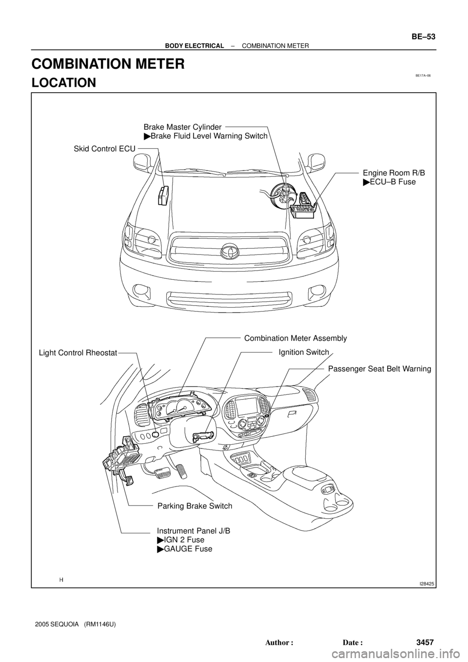
BE17A±06
I28425
Brake Master Cylinder
� Brake Fluid Level Warning Switch
Engine Room R/B
� ECU±B Fuse
Light Control Rheostat
Combination Meter Assembly
Instrument Panel J/B
� IGN 2 Fuse
� GAUGE Fuse
Parking Brake SwitchIgnition Switch
Passenger Seat Belt Warning
Skid Control ECU
± BODY ELECTRICALCOMBINATION METER
BE±53
3457 Author�: Date�:
2005 SEQUOIA (RM1146U)
COMBINATION METER
LOCATION
Page 3472 of 4323
BE260±05
I28409
Instrument Panel J/B
� ECU±IG Fuse
� GAUGE FuseOverhead Module
� Compass
BE±60
± BODY ELECTRICALCOMPASS
3464 Author�: Date�:
2005 SEQUOIA (RM1146U)
COMPASS
LOCATION
Page 3480 of 4323
BE03O±08
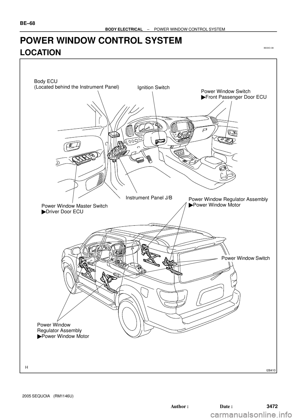
I28410
Power Window Regulator Assembly
� Power Window Motor
Power Window Switch
Power Window
Regulator Assembly
� Power Window MotorPower Window Master Switch
� Driver Door ECU
Ignition Switch
Instrument Panel J/BPower Window Switch
� Front Passenger Door ECU
Body ECU
(Located behind the Instrument Panel)
BE±68
± BODY ELECTRICALPOWER WINDOW CONTROL SYSTEM
3472 Author�: Date�:
2005 SEQUOIA (RM1146U)
POWER WINDOW CONTROL SYSTEM
LOCATION
Page 3486 of 4323
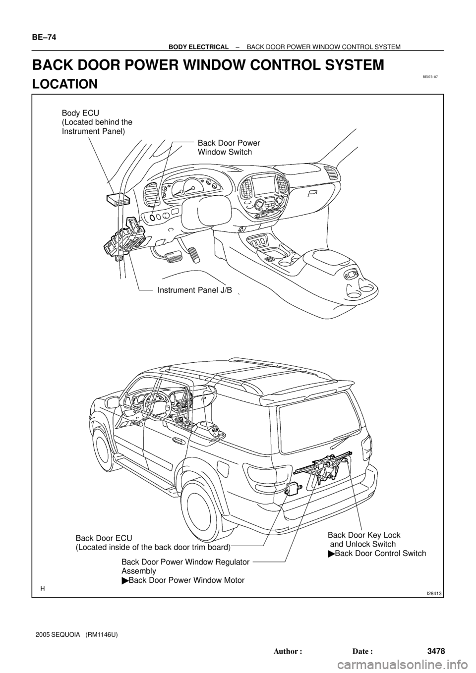
BE073±07
I28413
Back Door Power
Window Switch
Instrument Panel J/B
Back Door Key Lock
and Unlock Switch
� Back Door Control Switch
Back Door Power Window Regulator
Assembly
� Back Door Power Window Motor Body ECU
(Located behind the
Instrument Panel)
Back Door ECU
(Located inside of the back door trim board)
BE±74
± BODY ELECTRICALBACK DOOR POWER WINDOW CONTROL SYSTEM
3478 Author�: Date�:
2005 SEQUOIA (RM1146U)
BACK DOOR POWER WINDOW CONTROL SYSTEM
LOCATION
Page 3488 of 4323

4. INSPECT BACK DOOR POWER WINDOW PULSE
SENSOR (Usi")
I28582
Back Door ECU:
A
1716
I28583
GND BE±76
± BODY ELECTRICALBACK DOOR POWER WINDOW CONTROL SYSTEM
3480 Author�: Date�:
2005 SEQUOIA (RM1146U)
4. INSPECT BACK DOOR POWER WINDOW PULSE
SENSOR (Using oscilloscope)
(a) Remove the back door ECU with the connectors still con-
nected.
(b) Connect the oscilloscope to terminals A±16 and A±17
and body ground.
(c) Operate the back door power window switch.
(d) Check the signal waveform according to the condition (s)
in the table below.
ItemCondition
Tool setting5V/DIV, 10 ms/DIV
Vehicle conditionIgnition switch ON
OK:
As shown in the illustration
5. INSPECT JAM PROTECTION FUNCTION
NOTICE:
Be careful not to get any part of your body caught when
checking.
HINT:
When performing resetting of the limit switch, do checking after
repeating up and down of the glass with automatic operation.
(a) Confirmation of AUTO up operation:
Confirm that the window will close fully with AUTO up op-
eration.
(b) Checking operation of the jam protection function:
(1) Raise the window with AUTO up operation and
check that the window goes down when it touches
the inserted handle of the hammer.
(2) Confirm that the window will then stop going down
after about 200 mm (7.87 in).
HINT:
When removing the glass, glass guide, regulator, etc. be sure
to perform a check of the jam protection function.
If the jam protection is not functioning properly, adjust the power
window motor switch and pulse switch.
Page 3489 of 4323

ADJUSTMENT
1. RESET (INITIALIZE) POWER WINDOW REGULATOR MOTOR
NOTICE:
Resetting t")
BE2MN±01
± BODY ELECTRICALBACK DOOR POWER WINDOW CONTROL SYSTEM
BE±77
3481 Author�: Date�:
2005 SEQUOIA (RM1146U)
ADJUSTMENT
1. RESET (INITIALIZE) POWER WINDOW REGULATOR MOTOR
NOTICE:
Resetting the power window regulator motor (initializing the pulse sensor) is necessary if: 1) the bat-
tery terminal cable is disconnected; 2) the back door ECU, wire harness, power window regulator
switch, power window regulator assembly and power window regulator motor are replaced or re-
moved/installed; or 3) the P/W fuse is replaced or removed. If resetting is not performed, the master
switch assembly will not be able to operate the AUTO operation function, jam protection function and
remote operation function.
(a) Turn the ignition switch ON.
(b) Open the power window halfway by pressing the power window switch.
(c) Fully pull up on the switch until the power window is fully closed and continue to hold the switch for
at least 1 second.
(d) Check that the AUTO UP/DOWN function operates normally.
If the AUTO UP/DOWN function operates normally, reset operations are complete. If abnormal, follow the
steps (e) to (g) below.
(e) Disconnect the negative battery terminal cable for 10 seconds.
(f) Connect the battery terminal cable.
(g) Perform the steps (a) to (d) again.
Page 3490 of 4323
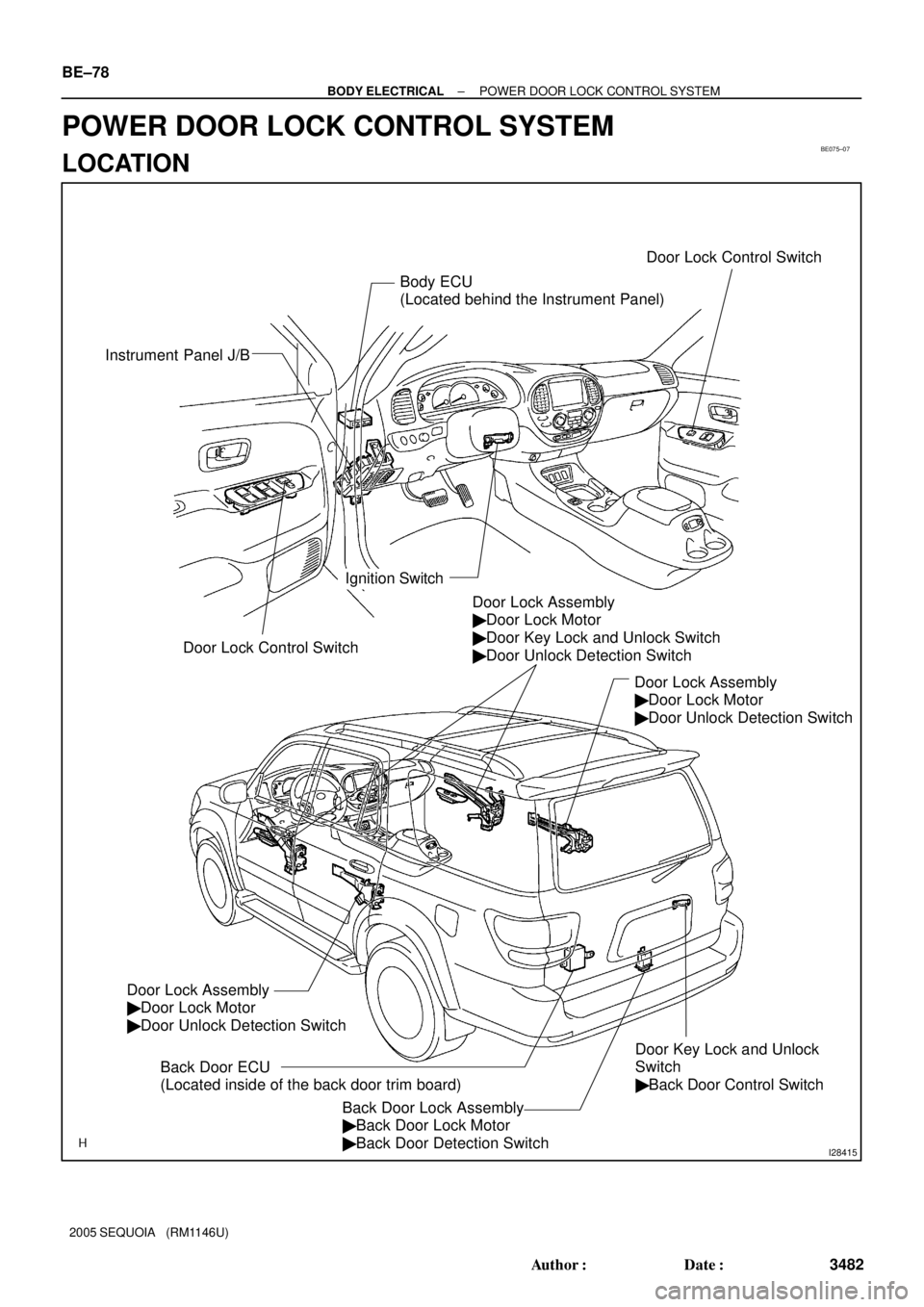
BE075±07
I28415
Door Lock Control Switch
Ignition SwitchDoor Lock Control Switch
Door Key Lock and Unlock
Switch
� Back Door Control Switch Instrument Panel J/B
Body ECU
(Located behind the Instrument Panel)
Door Lock Assembly
� Door Lock Motor
� Door Key Lock and Unlock Switch
� Door Unlock Detection Switch
Door Lock Assembly
� Door Lock Motor
� Door Unlock Detection Switch
Back Door Lock Assembly
� Back Door Lock Motor
� Back Door Detection Switch Back Door ECU
(Located inside of the back door trim board)
Door Lock Assembly
� Door Lock Motor
� Door Unlock Detection Switch
BE±78
± BODY ELECTRICALPOWER DOOR LOCK CONTROL SYSTEM
3482 Author�: Date�:
2005 SEQUOIA (RM1146U)
POWER DOOR LOCK CONTROL SYSTEM
LOCATION