Page 3064 of 4323
SA23P±03
F16856
4WD Control ECU
2WD/4HI and 4LO Switch
4WD and Center Diff. Lock
Indicator Light
(Combination Meter)
Transfer 4WD
Position Switch
Transfer L4 Position Switch
A.D.D. Actuator
Actuator Connector SA±60
± SUSPENSION AND AXLEA.D.D. CONTROL SYSTEM
3056 Author�: Date�:
2005 SEQUOIA (RM1146U)
A.D.D. CONTROL SYSTEM
LOCATION
Page 3076 of 4323
SA23W±03
R13196
SST
F07269
F07270
SA±72
± SUSPENSION AND AXLEFRONT UPPER SUSPENSION ARM
3068 Author�: Date�:
2005 SEQUOIA (RM1146U)
REMOVAL
1. REMOVE SHOCK ABSORBER WITH COIL SPRING
(See page SA±64)
2. DISCONNECT SPEED SENSOR WIRE HARNESS
CLAMPS
Remove the 2 bolts and speed sensor wire harness clamps
from the steering knuckle and upper suspension arm.
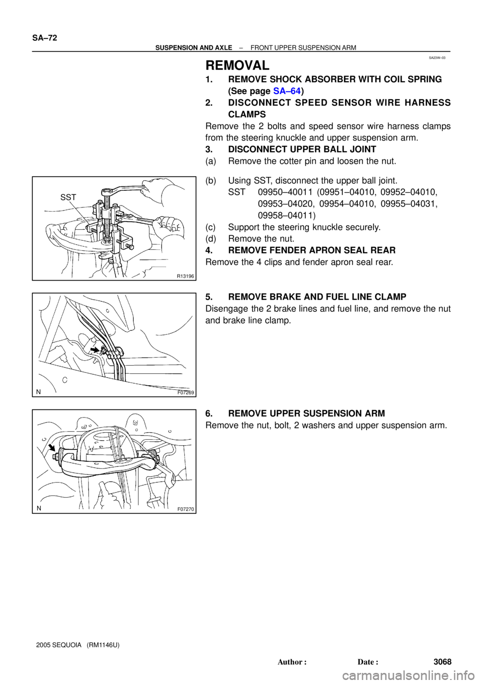
3. DISCONNECT UPPER BALL JOINT
(a) Remove the cotter pin and loosen the nut.
(b) Using SST, disconnect the upper ball joint.
SST 09950±40011 (09951±04010, 09952±04010,
09953±04020, 09954±04010, 09955±04031,
09958±04011)
(c) Support the steering knuckle securely.
(d) Remove the nut.
4. REMOVE FENDER APRON SEAL REAR
Remove the 4 clips and fender apron seal rear.
5. REMOVE BRAKE AND FUEL LINE CLAMP
Disengage the 2 brake lines and fuel line, and remove the nut
and brake line clamp.
6. REMOVE UPPER SUSPENSION ARM
Remove the nut, bolt, 2 washers and upper suspension arm.
Page 3091 of 4323
SA245±05
R13300
R13425
SST
R12863
SST
± SUSPENSION AND AXLEFRONT LOWER BALL JOINT
SA±87
3083 Author�: Date�:
2005 SEQUOIA (RM1146U)
REMOVAL
1. REMOVE FRONT WHEEL
2. LOOSEN 4 LOWER BALL JOINT SET BOLTS
HINT:
Do not remove the bolts.
3. DISCONNECT TIE ROD END
(a) Remove the cotter pin and nut from the tie rod end.
(b) Using SST, disconnect the tie rod end from the lower ball
joint.
SST 09610±20012
4. REMOVE LOWER BALL JOINT
(a) Remove the cotter pin and nut from the lower ball joint.
(b) Using SST, disconnect the lower ball joint from the lower
suspension arm.
SST 09628±62011
(c) Remove the 4 lower ball joint set bolts.
(d) While lifting the upper suspension arm and steering
knuckle, remove the lower ball joint.
(e) Support the upper suspension arm and steering knuckle
securely.
Page 3107 of 4323
SA24C±02
F14274
F14290
Nut
Washer
± SUSPENSION AND AXLEREAR WHEEL HUB BOLT
SA±103
3099 Author�: Date�:
2005 SEQUOIA (RM1146U)
REAR WHEEL HUB BOLT
REPLACEMENT
1. REMOVE REAR WHEEL
2. REMOVE BRAKE CALIPER AND DISC
(a) Remove the 2 bolts, brake caliper and disc.
(b) Support the brake caliper securely.
3. REMOVE HUB BOLT (See page SA±97)
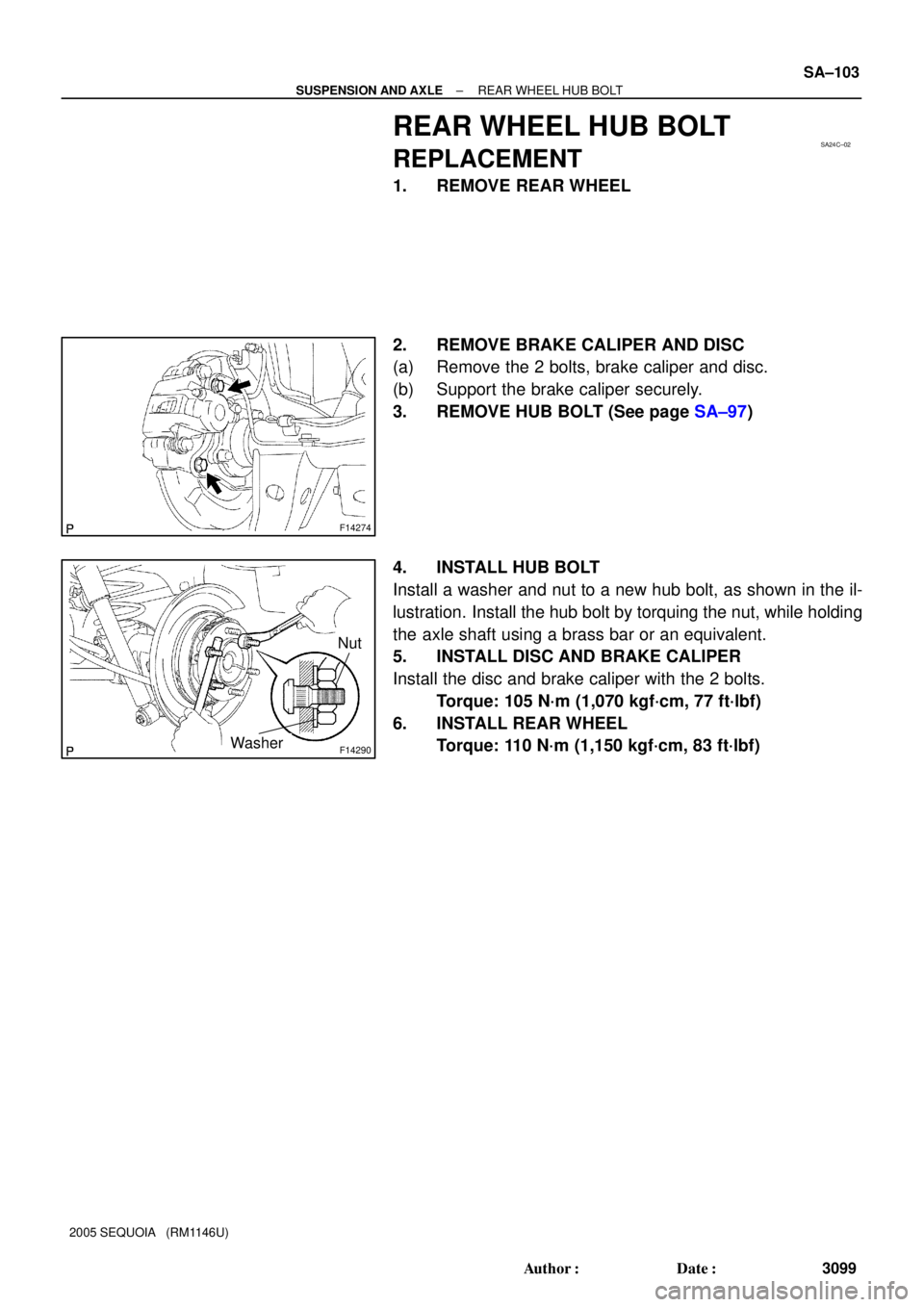
4. INSTALL HUB BOLT
Install a washer and nut to a new hub bolt, as shown in the il-
lustration. Install the hub bolt by torquing the nut, while holding
the axle shaft using a brass bar or an equivalent.
5. INSTALL DISC AND BRAKE CALIPER
Install the disc and brake caliper with the 2 bolts.
Torque: 105 N´m (1,070 kgf´cm, 77 ft´lbf)
6. INSTALL REAR WHEEL
Torque: 110 N´m (1,150 kgf´cm, 83 ft´lbf)
Page 3116 of 4323
F14294
Matchmarks
F14295
SA±112
± SUSPENSION AND AXLEREAR DIFFERENTIAL CARRIER
3108 Author�: Date�:
2005 SEQUOIA (RM1146U)
7. DISCONNECT REAR PROPELLER SHAFT
(a) 4WD:
(1) Place matchmarks on the propeller shaft and differ-
ential flange.
(2) Remove the 4 nuts, bolts, washers and disconnect
the propeller shaft.
Torque: 74 N´m (755 kgf´cm, 55 ft´lbf)
(b) 2WD:
(1) Place matchmarks on the propeller shaft and differ-
ential flange.
(2) Remove the 4 nuts, stud bolts, washers and discon-
nect the propeller shaft.
Torque: 74 N´m (755 kgf´cm, 55 ft´lbf)
(c) Support the propeller shaft securely.
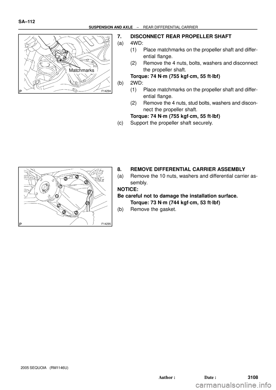
8. REMOVE DIFFERENTIAL CARRIER ASSEMBLY
(a) Remove the 10 nuts, washers and differential carrier as-
sembly.
NOTICE:
Be careful not to damage the installation surface.
Torque: 73 N´m (744 kgf´cm, 53 ft´lbf)
(b) Remove the gasket.
Page 3158 of 4323

SA±154
± SUSPENSION AND AXLEELECTRONIC MODULATED AIR SUSPENSION
3150")
F19817
O±ring
Plate
F19818
CardboardO±ring
Plate
F19819
Connector No.2
F14103
HousingClaw
Connector No. 1
Air tube
Port (Hole)
SA±154
± SUSPENSION AND AXLEELECTRONIC MODULATED AIR SUSPENSION
3150 Author�: Date�:
2005 SEQUOIA (RM1146U)
(5) Insert a screwdriver into the circular hole on the
housing, and remove the connector No.2, the 2 O±
rings and the plate from the housing.
HINT:
The O±rings, plate and connector No.2 are non±reusable parts.
(b) Install 2 O±rings and the plate.
(1) Apply MP grease to 2 new O±rings and plate and
install them to the straight tube or an equivalent.
NOTICE:
Install the plate between the O±rings.
Keep foreign matter from adhering to the O±rings and the
height control tube in order to prevent air leaks.
(2) Insert the tube on which the 2 O±rings and plate are
installed into the housing, and then push it in lightly
with a piece of rolled up cardboard.
(3) Push the connector No.2 into the housing to where
a clicking sound is heard.
(c) Install the height control tube.
(1) Push the tube and connector No.1 into the housing
to where a clicking sound is heard.
NOTICE:
�The port (hole) of the housing should be set in the
position 90° from the claws of connector No. 1.
�Pull the tube lightly to make sure that it is securely
connected.
Page 3175 of 4323
SA2CW±01
F16828
F16828
± SUSPENSION AND AXLESUSPENSION CONTROL ECU
SA±171
3167 Author�: Date�:
2005 SEQUOIA (RM1146U)
SUSPENSION CONTROL ECU
REPLACEMENT
1. DISCONNECT CABLE FROM NEGATIVE BATTERY
TERMINAL
2. REMOVE INTEGRATION CONTROL PANEL
(See page BO±89)
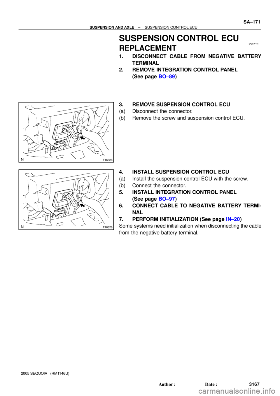
3. REMOVE SUSPENSION CONTROL ECU
(a) Disconnect the connector.
(b) Remove the screw and suspension control ECU.
4. INSTALL SUSPENSION CONTROL ECU
(a) Install the suspension control ECU with the screw.
(b) Connect the connector.
5. INSTALL INTEGRATION CONTROL PANEL
(See page BO±97)
6. CONNECT CABLE TO NEGATIVE BATTERY TERMI-
NAL
7. PERFORM INITIALIZATION (See page IN±20)
Some systems need initialization when disconnecting the cable
from the negative battery terminal.
Page 3212 of 4323
BR0JS±14
F13316
± BRAKEREAR BRAKE CALIPER
BR±37
3204 Author�: Date�:
2005 SEQUOIA (RM1146U)
REMOVAL
1. REMOVE REAR WHEEL
Torque: 110 N´m (1,122 kgf´cm, 81 ft´lbf)
2. DISCONNECT FLEXIBLE HOSE
Remove the union bolt and gasket from the caliper, then discon-
nect the flexible hose from the caliper. Use a container to catch
brake fluid as it drains out.
Torque: 31 N´m (320 kgf´cm, 23 ft´lbf)
HINT:
Securely set the flexible hose between the projections of the
caliper.
3. REMOVE CALIPER
(a) Remove the 2 sliding pins.
Torque: 88 N´m (900 kgf´cm, 65 ft´lbf)
(b) Remove the caliper from the torque plate.
4. REMOVE 2 BRAKE PADS WITH ANTI±SQUEAL SHIM
5. REMOVE 4 PAD SUPPORT PLATES

Transfer 4WD
Position Switch
Transfer L4 Position Switch
A.D.D. Actuator
Actuator")