Page 2362 of 4323
DIDBP±01
I27727
Instrument Panel J/B
� RAD NO. 2 Fuse
� ECU±B Fuse
� AM1 FuseEngine Room J/B
� RAD NO. 1 Fuse
� RAD NO. 3 Fuse
Steering Pad
Switch
Ignition SwitchDisc Player
Controller
(*1)
Stereo
Component
Amplifier
Multi±display
Controller (*1)
VTR
Terminal
(*1)Headphone
Terminal
(*1) (*2)
Radio and
Navigation Assy GPS Antenna
TweeterTelevision Display Assy (*1)
Rear Seat Audio
Controller Assy (*2)
Rear Door SpeakerRear Door Speaker
Front Door Speaker
and Woofer
Front Door Speaker
and Woofer
*1: w/ RSE System
*2: w/ RSA System
DI±2160
± DIAGNOSTICSNAVIGATION SYSTEM
2354 Author�: Date�:
2005 SEQUOIA (RM1146U)
LOCATION
Page 2364 of 4323

DIDBR±01
I28195
I28196
I28197
DI±2162
± DIAGNOSTICSNAVIGATION SYSTEM
2356 Author�: Date�:
2005 SEQUOIA (RM1146U)
SYSTEM DESCRIPTION
1. SYSTEM NORMAL CONDITION CHECK
(a) If the symptom is applicable to any of the following, it is intended behavior, and not a malfunction.
SymptomAnswer
A longer route than expected is chosen.Depending on the road conditions, the navigation ECU may determine that a longer
route is quicker.
Even when distance priority is high, the shortest route is not
shown.Some paths may not be advised due to safety concerns.
When the vehicle is put into motion immediately after the
engine starts, the navigation system deviates from the actu-
al position.If the vehicle starts before the navigation system activates, the system may not
react.
When running on certain types of roads, especially new
roads, the vehicle position deviates from the actual position.When the vehicle is driving on new roads not available on the map disc, the system
attempts to match it to another nearby road, causing the position mark to deviate.
(b) The following symptoms are not a malfunction, but are
caused by errors inherent in the GPS, gyro sensor, speed
sensor, and navigation ECU.
(1) The current position mark may be displayed on a
nearby parallel road.
(2) Immediately after a fork in the road, the current ve-
hicle position mark may be displayed on the wrong
road.
(3) When the vehicle turns right or left at an intersec-
tion, the current vehicle position mark may be dis-
played on a nearby parallel road.
Page 2366 of 4323
I28203
I28204
I28187
Radio and Display Assy
Navigation ECURadio and Navigation Assy DI±2164
± DIAGNOSTICSNAVIGATION SYSTEM
2358 Author�: Date�:
2005 SEQUOIA (RM1146U)
(9) When the vehicle runs on the snowy road or a
mountain path with the chains installed or using a
spare tire, the current vehicle position mark may
deviate from the correct position.
(10) When a tire is changed, the current vehicle position
mark may deviate from the correct position.
HINT:
�Diameter of the tire may change, causing a speed sensor
error.
�Performing the ºtire changeº in calibration mode will allow
the system to correct the current vehicle position faster.
2. Radio and navigation assy outline
Conventionally, 2 separate devices, a ºradio and display assyº and a ºnavigation ECUº are used. This model
has adopted a new type, combining these devices into a single unit.
Page 2367 of 4323

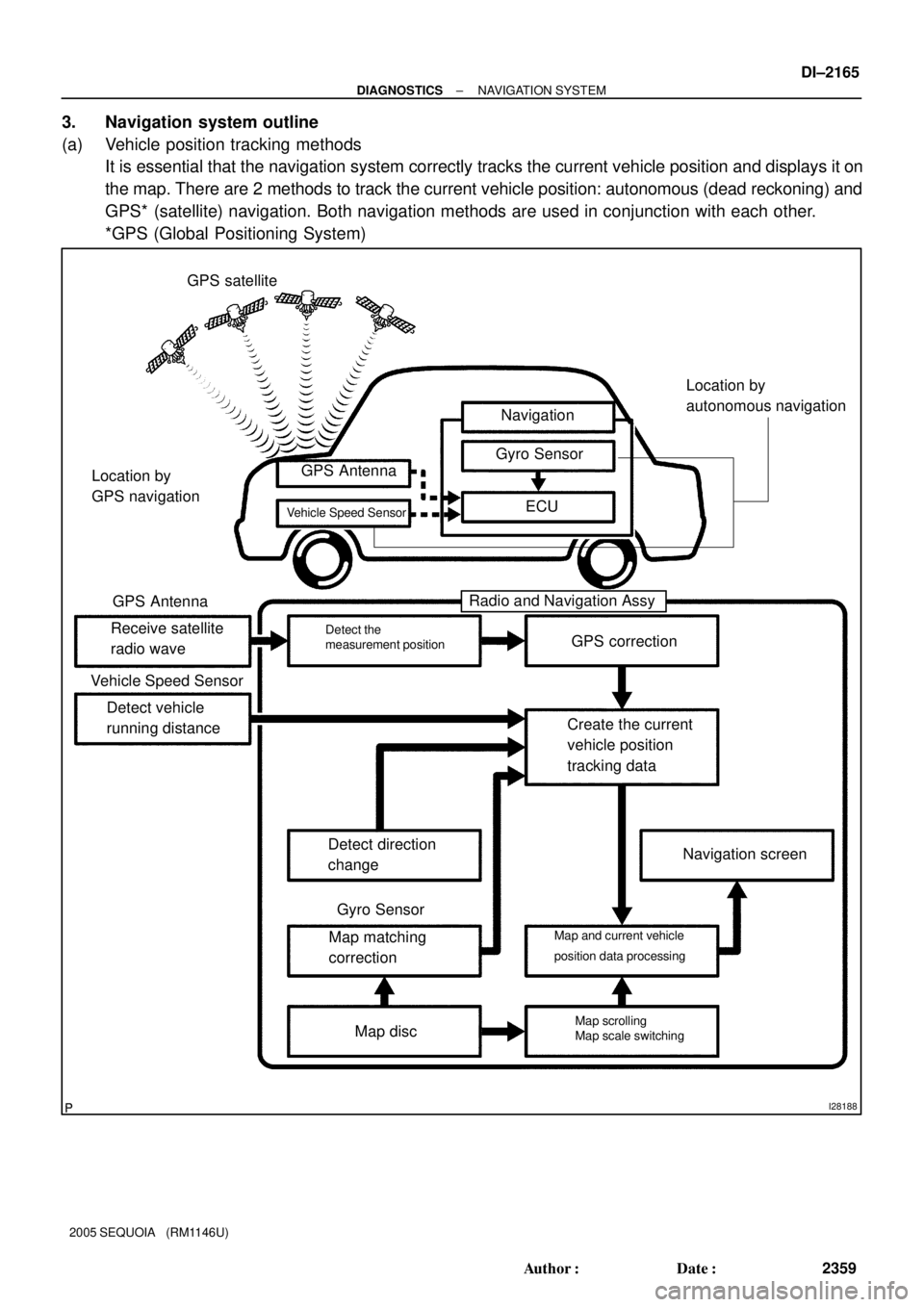
I28188
GPS satellite
Navigation
Gyro Sensor
ECU GPS Antenna
Receive satellite
radio waveGPS correction
Create the current
vehicle position
tracking data
Navigation screen
Map disc Map matching
correction Detect direction
change Detect vehicle
running distance
Radio and Navigation Assy
Detect the
measurement position
Map scrolling
Map scale switching Map and current vehicle
position data processing Vehicle Speed Sensor
GPS Antenna
Vehicle Speed SensorLocation by
GPS navigation
Gyro Sensor
Location by
autonomous navigation
± DIAGNOSTICSNAVIGATION SYSTEM
DI±2165
2359 Author�: Date�:
2005 SEQUOIA (RM1146U)
3. Navigation system outline
(a) Vehicle position tracking methods
It is essential that the navigation system correctly tracks the current vehicle position and displays it on
the map. There are 2 methods to track the current vehicle position: autonomous (dead reckoning) and
GPS* (satellite) navigation. Both navigation methods are used in conjunction with each other.
*GPS (Global Positioning System)
Page 2368 of 4323

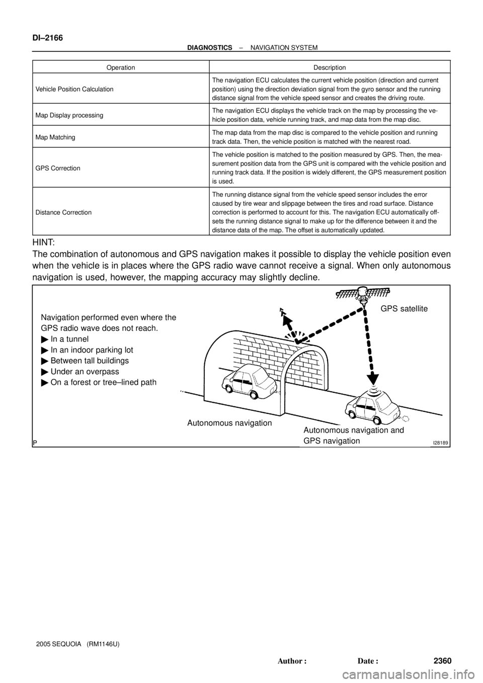
I28189
Navigation performed even where the
GPS radio wave does not reach.
� In a tunnel
� In an indoor parking lot
� Between tall buildings
� Under an overpass
� On a forest or tree±lined path
Autonomous navigation
Autonomous navigation and
GPS navigationGPS satellite DI±2166
± DIAGNOSTICSNAVIGATION SYSTEM
2360 Author�: Date�:
2005 SEQUOIA (RM1146U)Operation
Description
Vehicle Position Calculation
The navigation ECU calculates the current vehicle position (direction and current
position) using the direction deviation signal from the gyro sensor and the running
distance signal from the vehicle speed sensor and creates the driving route.
Map Display processingThe navigation ECU displays the vehicle track on the map by processing the ve-
hicle position data, vehicle running track, and map data from the map disc.
Map MatchingThe map data from the map disc is compared to the vehicle position and running
track data. Then, the vehicle position is matched with the nearest road.
GPS Correction
The vehicle position is matched to the position measured by GPS. Then, the mea-
surement position data from the GPS unit is compared with the vehicle position and
running track data. If the position is widely different, the GPS measurement position
is used.
Distance Correction
The running distance signal from the vehicle speed sensor includes the error
caused by tire wear and slippage between the tires and road surface. Distance
correction is performed to account for this. The navigation ECU automatically off-
sets the running distance signal to make up for the difference between it and the
distance data of the map. The offset is automatically updated.
HINT:
The combination of autonomous and GPS navigation makes it possible to display the vehicle position even
when the vehicle is in places where the GPS radio wave cannot receive a signal. When only autonomous
navigation is used, however, the mapping accuracy may slightly decline.
Page 2369 of 4323

I28190
GPS Current longitude/latitude/altitude is determined using the radio wave arrival time from four satellites.
± DIAGNOSTICSNAVIGATION SYSTEM
DI±2167
2361 Author�: Date�:
2005 SEQUOIA (RM1146U)
(b) Autonomous navigation
This method determines the relative vehicle position based on the running track determined by the
gyro and vehicle speed sensors located in the navigation ECU.
(1) Gyro sensor
Calculates the direction by detecting angular velocity. It is located in the radio and navigation
assy.
(2) Vehicle speed sensor
Used to calculate the vehicle running distance.
(c) GPS navigation (Satellite navigation)
This method detects the absolute vehicle position using radio wave from a GPS satellite.
* GPS satellites were launched by the U.S. Department of Defence for military purposes.
Number of satellitesMeasurementDescription
2 or lessMeasurement impossibleVehicle position cannot be obtained because the number of satellites is not enough.
32±dimensional measure-
ment is possibleVehicle position is obtained based on the current longitude and latitude (This is less precise
than 3±dimensional measurement).
43±dimensional measure-
ment is possibleVehicle position is obtained based on the current longitude, latitude and altitude.
Page 2371 of 4323

± DIAGNOSTICSNAVIGATION SYSTEM
DI±2169
2363 Author�: Date�:
2005 SEQUOIA (RM1146U)
4. DVD (Digital Versatile Disc) player outline (for navigation map)
The navigation ECU uses a laser pickup to read the digital signals recorded on a DVD.
HINT:
�Do not disassemble any part of the navigation system.
�Do not apply oil to the navigation system.
�Do not insert anything but a DVD into the navigation system.
CAUTION:
Because the navigation system uses an invisible laser beam, do not look directly at the laser pickup.
Be sure to only operate the navigation as instructed.
5. CD (Compact Disc) player outline
A CD player uses a laser pickup to read digital signals recorded on a CD. By converting the digital signals
to analog, it can play music and other things. In general, CD players can play a 4.7±inch (12 cm) or 3.2±inch
(8 cm) disc.
HINT:
�Do not disassemble any part of the CD player.
�Do not apply oil to the CD player.
�Do not insert anything but a CD into the CD player.
CAUTION:
Because the CD player uses an invisible laser beam, do not look directly at the laser pickup. Be sure
to only operate the player as instructed.
Page 2374 of 4323

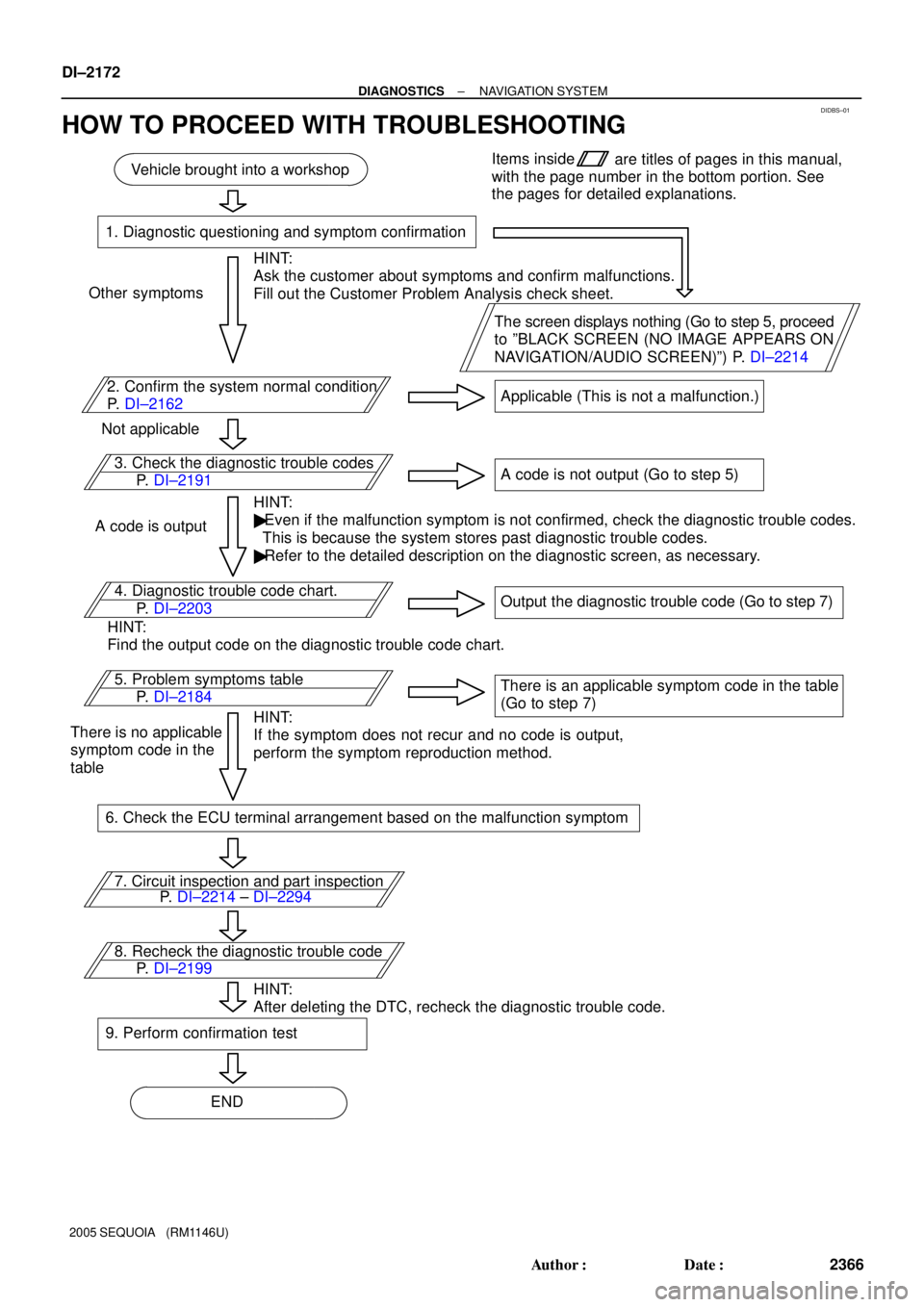
DIDBS±01
Vehicle brought into a workshop
1. Diagnostic questioning and symptom confirmation
HINT:
Ask the customer about symptoms and confirm malfunctions.
Fill out the Customer Problem Analysis check sheet.
The screen displays nothing (Go to step 5, proceed
to ºBLACK SCREEN (NO IMAGE APPEARS ON
NAVIGATION/AUDIO SCREEN)º) P. DI±2214 Other symptoms
2. Confirm the system normal condition
P. DI±2162Applicable (This is not a malfunction.)
Not applicable
3. Check the diagnostic trouble codes
HINT:
� Even if the malfunction symptom is not confirmed, check the diagnostic trouble codes.
This is because the system stores past diagnostic trouble codes.
� Refer to the detailed description on the diagnostic screen, as necessary. A code is outputA code is not output (Go to step 5)
4. Diagnostic trouble code chart.
HINT:
Find the output code on the diagnostic trouble code chart.Output the diagnostic trouble code (Go to step 7)
5. Problem symptoms table
HINT:
If the symptom does not recur and no code is output,
perform the symptom reproduction method.There is an applicable symptom code in the table
(Go to step 7)
There is no applicable
symptom code in the
table
6. Check the ECU terminal arrangement based on the malfunction symptom
7. Circuit inspection and part inspection
8. Recheck the diagnostic trouble code
HINT:
After deleting the DTC, recheck the diagnostic trouble code.
9. Perform confirmation test
ENDItems inside
are titles of pages in this manual,
with the page number in the bottom portion. See
the pages for detailed explanations.
P. DI±2191
P. DI±2214 ± DI±2294 P. DI±2203
P. DI±2184
P. DI±2199
DI±2172
± DIAGNOSTICSNAVIGATION SYSTEM
2366 Author�: Date�:
2005 SEQUOIA (RM1146U)
HOW TO PROCEED WITH TROUBLESHOOTING