Page 2192 of 4323
I28499
Built±in Type Amplifier:
Radio Receiver Assy A36
ACC Cut Relay Sub J/B No. 3
Instrument Panel J/B
Engine Room J/BTo ECM
Battery
IFR2
R2
R2 12
3A1
3A
1
4 3 W±R
2
GR B C B±O
J37 J38
IA124
L±Y L±Y GR
2B
2C8
2D1 RAD No. 1
ECU±BShort Pin 3
W±R
BRB RAD No. 2
3
1 6AM1 212 1
P
31ALT
5
B
I18
Ignition SWW±L1 2
AACC+B
GND BU+B 4 3
7 W±R
1J
1E
1L 1C1C1F
ACCAM1
GR
8
F10
Fusible Link Block
4 WJ/C
J12
Junction
Connector DI±1990
± DIAGNOSTICSAUDIO SYSTEM
2184 Author�: Date�:
2005 SEQUOIA (RM1146U)
CIRCUIT INSPECTION
Power source circuit (Radio receiver assy)
CIRCUIT DESCRIPTION
This circuit provides power to the radio receiver assy.
WIRING DIAGRAM
DID9U±01
Page 2193 of 4323
I28498
11 Radio Receiver Assy
ACC+B
1
R420
GND GR 1
RAD No. 24 3 A36
ACC Cut Relay
P
31AM1 ACC12 Sub J/B No. 3
3AW±R
W±R1
IA124
L±Y L±Y
2B
3
2C8
2D1 Engine Room J/B
RAD No. 1
ECU±BShort Pin 1J3
1E
W±R
1L1
1C6AM12
ALT
5
B
Battery
IOBR Separate Type Amplifier:
R4 R4 3A
I18
Ignition SWW±LB 212 1
1C 1FGR
GRB C B±O
J37To ECM
J38
Instrument Panel J/B
1 2BU+B
W
8
4 F10
Fusible Link BlockJ/C
± DIAGNOSTICSAUDIO SYSTEM
DI±1991
2185 Author�: Date�:
2005 SEQUOIA (RM1146U)
Page 2195 of 4323
I28500
GR 1
4 3 A36
ACC Cut Relay
12 Sub J/B No. 3
3AW±R 1
2 3A
GRB C B±O
J37To ECM
J38
RAD No. 2
3
1 6AM1 212 1Instrument Panel J/B
1 2
P
3
AM1
ACC W±R
W±LALT
5
B
Battery W±RILI2
L±W
2A
2C8
2D1 Engine Room J/B
RAD No. 3
ECU±BShort Pin 3
B B
BBJ11
J10 J11 L±W
IOBR
BRS10
S9
S9S9
S9 12
10
15
161ACC
B2+
B+
GND
E Stereo Component
Amplifier Assy
1J 1E
1L 1C 1C 1FJ/C
J/C
GR
8
4 F10
Fusible Link Block WL±W L±W
I18
Ignition SW
± DIAGNOSTICSAUDIO SYSTEM
DI±1993
2187 Author�: Date�:
2005 SEQUOIA (RM1146U)
Power source circuit (Stereo component amplifier assy)
CIRCUIT DESCRIPTION
This circuit provides power to the stereo component amplifier assy.
WIRING DIAGRAM
DID9V±01
Page 2201 of 4323
I28476
R6
Light Control
Rheostat AssyRadio Receiver Assy
J/C
Steering Pad Switch
Spiral Cable
Sub±assy From
TAILLIGHT
RelayILL±
GND J/C
ILL+ W±G
GJ39 J40
J39 J40
J39 J40R4
R19 R4R3
R2 W±G
G
G
G A B
A
AAB
ILL±
T12
5
2
10
6 A±1
A±10C9±1
BR±W C9±10(*1)
*1: Separate Type Amplifier
*2: Built±in Type Amplifier(*2) (*1) (*2)
6
4
± DIAGNOSTICSAUDIO SYSTEM
DI±1999
2193 Author�: Date�:
2005 SEQUOIA (RM1146U)
Illumination circuit
CIRCUIT DESCRIPTION
Power is supplied to the radio receiver panel illumination when the light control switch is in the TAIL or HEAD
position. The body ECU determines the external brightness based on the brightness level detected by the
automatic light control sensor, and then operates the tail relay. Power can also be supplied by operating the
relay.
The intensity of the radio receiver panel illumination can be adjusted by the rheostat switch.
WIRING DIAGRAM
DID9X±01
Page 2229 of 4323

Noise occurs
INSPECTION PROCEDURE
1 Check of speaker installation.
CHECK:
Check if each speaker is securely installed.")
± DIAGNOSTICSAUDIO SYSTEM
DI±2027
2221 Author�: Date�:
2005 SEQUOIA (RM1146U)
Noise occurs
INSPECTION PROCEDURE
1 Check of speaker installation.
CHECK:
Check if each speaker is securely installed.
OK:
Each speaker is securely installed.
HINT:
The radio is equipped with a noise prevention system that blocks excessively loud noise. If such noise oc-
curs, check the all wiring is proper and that the antenna installation part ground and noise±prevention equip-
ment are installed.
Condition in which noise occursNoise type
Noise increases when the accelerator pedal is depressed, but stops when
the engine is stopped.Generator noise
Noise occurs during A/C or the heater operation.Blower motor noise
Noise occurs when the vehicle accelerates rapidly on an unpaved road or
after the ignition switch is turned on.Fuel pump noise
Noise occurs when the horn switch is pressed and released or when pressed
and held.Horn noise
Quiet noise occurs while the engine is running, but stops when the engine is
stopped.Ignition noise
Noise occurs synchronously with the blink of the turn signal.Flasher noise
Noise occurs during window washer operation.Washer noise
Noise occurs while the engine is running, and it continues even after the en-
gine is stopped.Water temperature sensor noise
Noise occurs during wiper operation.Wiper noise
Noise occurs when the brake pedal is depressed.Stop light switch noise
Others.Static electricity stored on the vehicle
HINT:
�Identify the condition under which the noise occurs, and check the noise filter on the related part.
�First ensure that the noise is not coming from the outside. Failure to do so makes noise source detec-
tion difficult and may lead to a misdiagnosis.
�Noise should be removed in descending order of loudness.
NG Install it properly.
OK
Identification of noise source (See page DI±1964).
DIDA3±01
Page 2247 of 4323
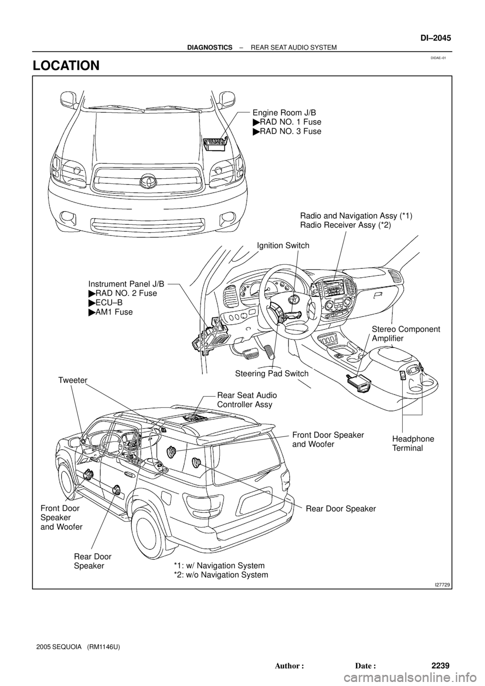
DIDAE±01
I27729
Radio and Navigation Assy (*1)
Radio Receiver Assy (*2)
Rear Door
Speaker Tweeter
Rear Door Speaker Front Door Speaker
and Woofer
Steering Pad Switch Instrument Panel J/B
� RAD NO. 2 Fuse
� ECU±B
� AM1 FuseEngine Room J/B
� RAD NO. 1 Fuse
� RAD NO. 3 Fuse
Ignition Switch
Rear Seat Audio
Controller Assy
Headphone
Terminal
Front Door
Speaker
and Woofer
Stereo Component
Amplifier
*1: w/ Navigation System
*2: w/o Navigation System
± DIAGNOSTICSREAR SEAT AUDIO SYSTEM
DI±2045
2239 Author�: Date�:
2005 SEQUOIA (RM1146U)
LOCATION
Page 2253 of 4323

TERMINALS OF ECU
1. REAR SEAT AUDIO CONTROLLER
Terminals No. (Symbols)Wiring ColorTermi")
DIDAL±01
I28334
R24
± DIAGNOSTICSREAR SEAT AUDIO SYSTEM
DI±2051
2245 Author�: Date�:
2005 SEQUOIA (RM1146U)
TERMINALS OF ECU
1. REAR SEAT AUDIO CONTROLLER
Terminals No. (Symbols)Wiring ColorTerminal
DescriptionConditionSpecified value
R24±1 ± Body ground
(SGN1 ± Body ground)Shielded ±
Body groundGroundAlwaysBelow 1 V
R24±2 ± R24±17
(HP1L ± GND)BR ± LGSound signal
(Output)RSA system is sounding (Headphone)
A waveform syn-
chronized with
sounds is output
R24±3 ± R24±17
(HP1R ± GND)BR ± LGSound signal
(Output)RSA system is sounding (Headphone)
A waveform syn-
chronized with
sounds is output
R24±6 ± R24±17
(R±L± ± GND)W ± LGSound signal
(Input)RSA system is sounding
A waveform syn-
chronized with
sounds is output
R24±7 ± R24±17
(R±L+ ± GND)W ± LGSound signal
(Input)RSA system is sounding
A waveform syn-
chronized with
sounds is output
R24±8 ± R24±17
(R±R± ± GND)W ± LGSound signal
(Input)RSA system is sounding
A waveform syn-
chronized with
sounds is output
R24±9 ± R24±17
(R±R+ ± GND)W ± LGSound signal
(Input)RSA system is sounding
A waveform syn-
chronized with
sounds is output
R24±10 ± Body ground
(SG1 ± Body ground)Shielded ±
Body groundGroundAlwaysBelow 1 V
R24±11 ± R24±17
(RMUT ± GND)LG ± LGMute signalAudio system is playing " Changing modeAbove 3.5 V "
Below 1 V
R24±12 ± R24±17
(+B ± GND)LG ± LGBatteryAlways10 to 14 V
R24±13 ± Body ground
(SGN2 ± Body ground)Shielded ±
Body groundGroundAlwaysBelow 1 V
R24±14 ± R24±17
(HP2L ± GND)BR ± LGSound signal
(Output)RSA system is sounding (Headphone)
A waveform syn-
chronized with
sounds is output
R24±15 ± R24±17
(HP2R ± GND)BR ± LGSound signal
(Output)RSA system is sounding (Headphone)
A waveform syn-
chronized with
sounds is output
R24±17 ± Body ground
(GND ± Body ground)LG ±
Body groundGroundAlwaysBelow 1 W
Page 2260 of 4323
DIDAM±01
I28496
B±O
24R24
Rear Seat Audio
Controller Assy
ACC
+B
17
GND 1228 C
4 3A36
ACC Cut
Relay
B 12 1Sub J/B No.3
3A
ID2 W±R
J/C
L±Y1
2
IA1 26 L±R
L±R
2B3
2C8
2D Engine Room J/B
ECU±BShort Pin
1 Instrument Panel J/B
W±R
AM11
3 2RAD No.2
W 1
P6
ALT
1B
BatteryLG To ECM
GR
RSE
2 2
1Engine Room R/B No.2J37
ID221
IMLG 3A
LG
12
ID2 J38
L±R
2 12
W±LRAD No.1
W±R
W±L 1
2B
3
AM1B
ACC
I18
Ignition SW 1C
1C 1E1F
1J
1LGR
PW±R
GR
W±B 58
4F10
Fusible Link Block DI±2058
± DIAGNOSTICSREAR SEAT AUDIO SYSTEM
2252 Author�: Date�:
2005 SEQUOIA (RM1146U)
CIRCUIT INSPECTION
Power source circuit (Rear seat audio controller)
CIRCUIT DESCRIPTION
This circuit provides the power to the rear seat audio controller.
WIRING DIAGRAM