Page 2281 of 4323
DIDAT±01
I27728
Radio and Navigation Assy (*1)
Radio Receiver Assy (*2)
Rear Door
SpeakerSteering Pad Switch
Instrument Panel J/B
� RAD NO. 2 Fuse
� ECU±B Fuse
� AM1 FuseEngine Room J/B
� RAD NO. 1 Fuse
� RAD NO. 3 Fuse
Ignition Switch
Headphone
Terminal
Front Door
Speaker and
Woofer
Stereo Component Amplifier
Multi±display
Controller
Sub±assy
*1: w/ Navigation System
*2: w/o Navigation SystemVTR TerminalDisc Player
Controller
Rear Door
Speaker
Front Door
Speaker and
Woofer
Tweeter
Television Display Assy
± DIAGNOSTICSREAR SEAT ENTERTAINMANT SYSTEM
DI±2079
2273 Author�: Date�:
2005 SEQUOIA (RM1146U)
LOCATION
Page 2283 of 4323

DIDAV±01
± DIAGNOSTICSREAR SEAT ENTERTAINMANT SYSTEM
DI±2081
2275 Author�: Date�:
2005 SEQUOIA (RM1146U)
SYSTEM DESCRIPTION
1. Outline
�As a unique feature of Rear Seat Entertainment (RSE) system, the front and rear seat occupants can
enjoy different audio±visual modes at the same time. Thus, this system offers enhanced entertainment
to the rear seat occupants.
�The rear seat occupants can control the audio±visual modes with the remote controller (switch assy),
and listen to audio by using wired or wireless headphones.
�The RSE system is controlled by the multi±display controller, and the communication among the audio
head unit, rear display assembly, and DVD player is established via an AVC±LAN (Audio Visual Com-
munication±Local Area Network).
2. Function of Main Component
Television Display Assy
�Displays DVD and video images in accordance with video signals from the RSE ECU.
�Receives signals from the remote controller and outputs them to the RSE ECU.
�Outputs audio signals to the wireless headphones in the form of infrared signals.
�Displays the audio±visual control screen.
�Displays the adjustment screen.
�Displays the diagnosis screen.
�The diagnosis screen appears when the diagnosis mode is started on the audio head unit.
Audio Head Unit
w/ Navigation system:
Radio and navigation assy
w/o Navigation system:
Radio receiver assy
�Outputs audio signals to the RSE ECU and the stereo component amplifier.
�Outputs a request to the RSE ECU to start the diagnosis mode.
RSE ECU (Multi±display Controller)
�Processes video and audio signals from the DVD player and video player and audio signals from the
audio head unit, and outputs them to the television display assembly and headphone terminals.
�Controls the distribution of the audio±visual mode to the front (audio head unit) and the rear (RSE).
Remote Controller (Switch Assy)Outputs various control signals of the RSE system to the television display assembly in the form of in-
frared signals.
Wireless Headphone
�Receives the audio signals from the television display assembly in the form of infrared signals.
�Volume adjustment of the wireless headphone can be done by using the volume equipped on the wire-
less headphone.
Headphone Terminal�Outputs audio signals to the wired headphones that are connected.
�Adjusts the volume of the wired headphones in accordance with volume control.
VTR TerminalThis terminal is for connecting the video player's video and audio output terminals.
Page 2292 of 4323

DIDB0±01
I28662
R23
R22R21
DI±2090
± DIAGNOSTICSREAR SEAT ENTERTAINMANT SYSTEM
2284 Author�: Date�:
2005 SEQUOIA (RM1146U)
TERMINALS OF ECU
1. MULTI±DISPLAY CONTROLLER SUB±ASSY
Symbols (Terminals No.)Wiring ColorTerminal DescriptionConditionSpecification
L± ± GND
(R23±7 ± R23±29)W ± YSound signal (Output)DVD system is playing
A waveform
synchronized
with sound is
output
L+ ± GND
(R23±8 ± R23±29)W ± YSound signal (Output)DVD system is playing
A waveform
synchronized
with sound is
output
R± ± GND
(R23±9 ± R23±29)W ± YSound signal (Output)DVD system is playing
A waveform
synchronized
with sound is
output
R+ ± GND
(R23±10 ± R23±29)W ± YSound signal (Output)DVD system is playing
A waveform
synchronized
with sound is
output
SG1 ± Body ground
(R23±11 ± Body ground)Shielded ± Body groundGroundAlwaysBelow 1 V
LMUT ± GND
(R23±12 ± R23±29)LG ± YMute signalDisc player controller is sounding
" changing modeAbove 3.5 V "
Below 1 V
+B1 ± GND
(R23±16 ± R23±29)Y ± YBatteryAlways10 to 14 V
(*1) SG3 ± Body ground
(R23±19 ± Body ground)Shielded ± Body groundGroundAlwaysBelow 1 V
(*1) SGN1 ± Body ground
(R23±20 ± Body ground)BR ± Body groundGroundAlwaysBelow 1 V
(*1) NTS1 ± GND
(R23±21 ± R23±29)BR ± YDisplay signalDVD system is displayedPulse genera-
tion
Page 2302 of 4323

I28277
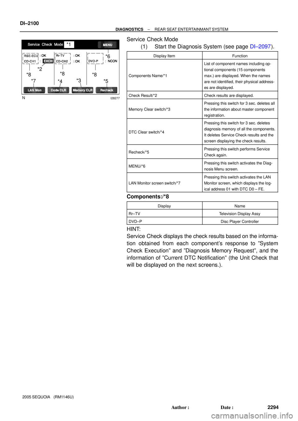
*1
*2
*4*3*6
*5 *7
*8 *8
*8
DI±2100
± DIAGNOSTICSREAR SEAT ENTERTAINMANT SYSTEM
2294 Author�: Date�:
2005 SEQUOIA (RM1146U)
Service Check Mode
(1) Start the Diagnosis System (see page DI±2097).
Display ItemFunction
Components Name/*1
List of component names including op-
tional components (15 components
max.) are displayed. When the names
are not identified, their physical address-
es are displayed.
Check Result/*2Check results are displayed.
Memory Clear switch/*3
Pressing this switch for 3 sec. deletes all
the information about master component
registration.
DTC Clear switch/*4
Pressing this switch for 3 sec. deletes
diagnosis memory of all the components.
It deletes Service Check results and the
screen displaying the check results.
Recheck/*5Pressing this switch performs Service
Check again.
MENU/*6Pressing this switch activates the Diag-
nosis Menu screen.
LAN Monitor screen switch/*7
Pressing this switch activates the LAN
Monitor screen, which displays the log-
ical address 01 with DTC D0 ± FE.
Components:/*8
DisplayName
Rr±TVTelevision Display Assy
DVD±PDisc Player Controller
HINT:
Service Check displays the check results based on the informa-
tion obtained from each component's response to ºSystem
Check Executionº and ºDiagnosis Memory Requestº, and the
information of ºCurrent DTC Notificationº (the Unit Check that
will be displayed on the next screens.).
Page 2305 of 4323

DIDB3±01
± DIAGNOSTICSREAR SEAT ENTERTAINMANT SYSTEM
DI±2103
2297 Author�: Date�:
2005 SEQUOIA (RM1146U)
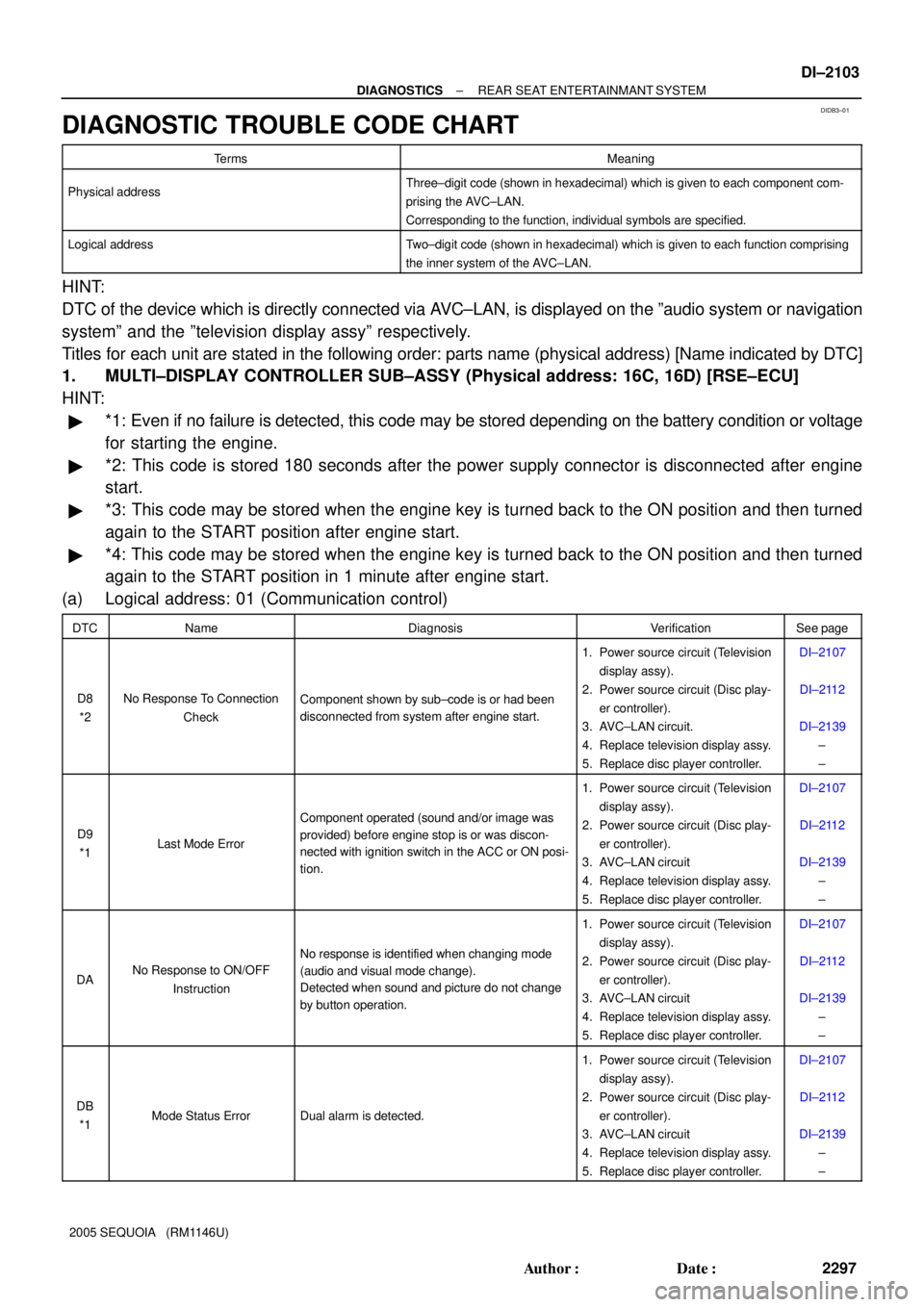
DIAGNOSTIC TROUBLE CODE CHART
TermsMeaning
Physical addressThree±digit code (shown in hexadecimal) which is given to each component com-
prising the AVC±LAN.
Corresponding to the function, individual symbols are specified.
Logical addressTwo±digit code (shown in hexadecimal) which is given to each function comprising
the inner system of the AVC±LAN.
HINT:
DTC of the device which is directly connected via AVC±LAN, is displayed on the ºaudio system or navigation
systemº and the ºtelevision display assyº respectively.
Titles for each unit are stated in the following order: parts name (physical address) [Name indicated by DTC]
1. MULTI±DISPLAY CONTROLLER SUB±ASSY (Physical address: 16C, 16D) [RSE±ECU]
HINT:
�*1: Even if no failure is detected, this code may be stored depending on the battery condition or voltage
for starting the engine.
�*2: This code is stored 180 seconds after the power supply connector is disconnected after engine
start.
�*3: This code may be stored when the engine key is turned back to the ON position and then turned
again to the START position after engine start.
�*4: This code may be stored when the engine key is turned back to the ON position and then turned
again to the START position in 1 minute after engine start.
(a) Logical address: 01 (Communication control)
DTCNameDiagnosisVerificationSee page
D8
*2No Response To Connection
CheckComponent shown by sub±code is or had been
disconnected from system after engine start.
1. Power source circuit (Television
display assy).
2. Power source circuit (Disc play-
er controller).
3. AVC±LAN circuit.
4. Replace television display assy.
5. Replace disc player controller.DI±2107
DI±2112
DI±2139
±
±
D9
*1Last Mode Error
Component operated (sound and/or image was
provided) before engine stop is or was discon-
nected with ignition switch in the ACC or ON posi-
tion.
1. Power source circuit (Television
display assy).
2. Power source circuit (Disc play-
er controller).
3. AVC±LAN circuit
4. Replace television display assy.
5. Replace disc player controller.DI±2107
DI±2112
DI±2139
±
±
DANo Response to ON/OFF
Instruction
No response is identified when changing mode
(audio and visual mode change).
Detected when sound and picture do not change
by button operation.
1. Power source circuit (Television
display assy).
2. Power source circuit (Disc play-
er controller).
3. AVC±LAN circuit
4. Replace television display assy.
5. Replace disc player controller.DI±2107
DI±2112
DI±2139
±
±
DB
*1Mode Status ErrorDual alarm is detected.
1. Power source circuit (Television
display assy).
2. Power source circuit (Disc play-
er controller).
3. AVC±LAN circuit
4. Replace television display assy.
5. Replace disc player controller.DI±2107
DI±2112
DI±2139
±
±
Page 2312 of 4323
I28486
J/C Sub J/B No.3
R2332 Multi±display Controller Sub±assy
ACC
R2316
+B1
R2329
GND IF3
1
IFC
4 3A36
ACC
Cut Relay
B 1
I18
Ignition SW12
12 3A W±R
W±R
1To ECM
IA126
L±R L±R
2D1
2C8Engine Room J/B
RAD No. 1
ECU±BShort Pin 3
W±L2
W±R 1C
3
1E 1J
W
IL1
IC6AM1
8
F10
FL Block
ALT
54
B
Battery
IM13
LG GR GR
L±Y GR
2 2 Engine Room R/B No. 2
Y
IF33
W±B 3AW±R
1
IF3
22B
P
3
ACCAM1
BB 1 2 W±LB±O
J37 J38
L±YY
RAD No. 2 1Instrument Panel J/B
2
1RSE
2C P DI±2110
± DIAGNOSTICSREAR SEAT ENTERTAINMANT SYSTEM
2304 Author�: Date�:
2005 SEQUOIA (RM1146U)
Power source circuit (Multi±display controller sub±assy)
CIRCUIT DESCRIPTION
This circuit provides power to the multi±display controller sub±assy.
WIRING DIAGRAM
DIDB5±01
Page 2344 of 4323
DI±2142
± DIAGNOSTICSREAR SEAT ENTERTAINMANT SYSTEM
2336 Author�: Date�:
2005 SEQUOIA (RM1146U)
4 Service check mode (Multi±display controller sub±assy).
CHECK:
Perform the service check (See page DI±2099).
Start the diagnosis system and read the check result for the radio and navigation assy.
RESULT:
ºNCONº is displayed or result is not displayed (RSE ECU)Go to step A
ºGOODº is displayedGo to step B
HINT:
�This system has 2 kinds of AVC±LAN: main AVC±LAN and sub AVC±LAN. The television display is
connected for the sub AVC±LAN.
�Perform the communication check for the diagnosis system (See page DI±2097).
B Replace radio and navigation assy.
A
Page 2345 of 4323

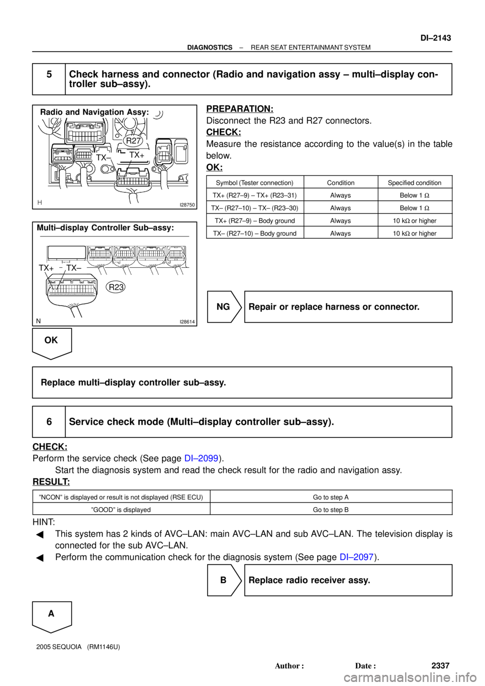
I28750
Radio and Navigation Assy:
TX±TX+
R27
I28614
TX+ Multi±display Controller Sub±assy:
R23TX±
± DIAGNOSTICSREAR SEAT ENTERTAINMANT SYSTEM
DI±2143
2337 Author�: Date�:
2005 SEQUOIA (RM1146U)
5 Check harness and connector (Radio and navigation assy ± multi±display con-
troller sub±assy).
PREPARATION:
Disconnect the R23 and R27 connectors.
CHECK:
Measure the resistance according to the value(s) in the table
below.
OK:
Symbol (Tester connection)ConditionSpecified condition
TX+ (R27±9) ± TX+ (R23±31)AlwaysBelow 1 W
TX± (R27±10) ± TX± (R23±30)AlwaysBelow 1 W
TX+ (R27±9) ± Body groundAlways10 kW or higher
TX± (R27±10) ± Body groundAlways10 kW or higher
NG Repair or replace harness or connector.
OK
Replace multi±display controller sub±assy.
6 Service check mode (Multi±display controller sub±assy).
CHECK:
Perform the service check (See page DI±2099).
Start the diagnosis system and read the check result for the radio and navigation assy.
RESULT:
ºNCONº is displayed or result is not displayed (RSE ECU)Go to step A
ºGOODº is displayedGo to step B
HINT:
�This system has 2 kinds of AVC±LAN: main AVC±LAN and sub AVC±LAN. The television display is
connected for the sub AVC±LAN.
�Perform the communication check for the diagnosis system (See page DI±2097).
B Replace radio receiver assy.
A