Page 1600 of 1897
SF0SM-05
B09119
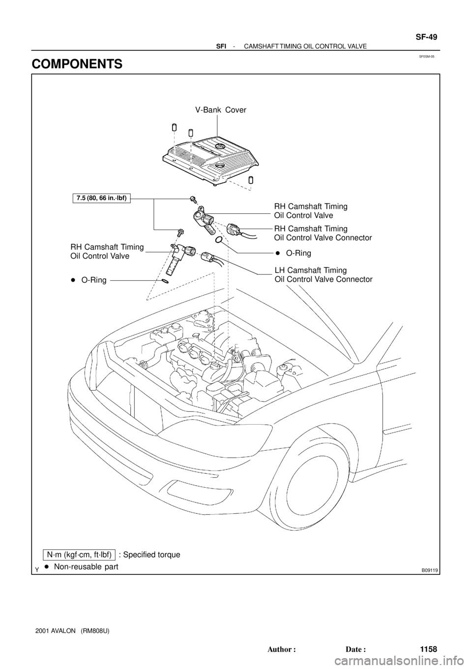
V-Bank Cover
� O-Ring
� Non-reusable part� O-RingRH Camshaft Timing
Oil Control Valve
RH Camshaft Timing
Oil Control Valve
RH Camshaft Timing
Oil Control Valve Connector
LH Camshaft Timing
Oil Control Valve Connector
N´m (kgf´cm, ft´lbf) : Specified torque
7.5 (80, 66 in.´lbf)
- SFICAMSHAFT TIMING OIL CONTROL VALVE
SF-49
1158 Author�: Date�:
2001 AVALON (RM808U)
COMPONENTS
Page 1604 of 1897
SF0ZY-03
A10518
5 mm
Hexagon
Wrench
B06691
SF-50
- SFICAMSHAFT TIMING OIL CONTROL VALVE
1159 Author�: Date�:
2001 AVALON (RM808U)
REMOVAL
1. REMOVE V-BANK COVER
(a) Using a 5 mm hexagon wrench, remove the 3 cap nuts.
(b) Loosen the V-bank cover fastener counterclockwise.
HINT:
At the time of installation, please refer to the following items.
Press down the V-bank cover fastener.
(c) Remove the V-bank cover.
2. REMOVE CAMSHAFT TIMING OIL CONTROL VALVES
(a) Disconnect the 2 camshaft oil control valve connectors.
(b) Remove the bolt, camshaft oil control valve and O-ring.
Remove the 2 camshaft oil control valves.
Torque: 7.5 N´m (80 kgf´cm, 66 in.´lbf)
(c) Remove the O-ring from the each camshaft oil control
valve.
HINT:
At the time of installation, please refer to the following items.
Use a new O-ring.
Page 1607 of 1897
SF06Q-05
B06679
ECT Switch
19 mm
Deep Socket
Wrench
Gasket
S01196S01699Z17274
Ohmmeter
Resistance kW
Temperature °C (°F) Acceptable 30
20
10
5
3
2
1
0.5
0.3
0.2
0.1
40 -20 0 20 60 80 100
(212) (176) (140) (104) (68) (32) (-4)
- SFIENGINE COOLANT TEMPERATURE (ECT) SENSOR
SF-73
1182 Author�: Date�:
2001 AVALON (RM808U)
ENGINE COOLANT
TEMPERATURE (ECT) SENSOR
INSPECTION
1. DRAIN ENGINE COOLANT
2. REMOVE ECT SENSOR
(a) Disconnect the ECT sensor connector.
(b) Using a 19 mm deep socket wrench, remove the ECT
sensor and gasket.
3. INSPECT ECT SENSOR
Using an ohmmeter, measure the resistance between the ter-
minals.
Resistance: Refer to the graph
If the resistance is not as specified, replace the ECT sensor.
4. REINSTALL ECT SENSOR
(a) Install a new gasket to the ECT sensor.
(b) Using a 19 mm deep socket, install the ECT sensor.
Torque: 20 N´m (200 kgf´cm, 14 ft´lbf)
(c) Connect the ECT sensor connector.
5. REFILL WITH ENGINE COOLANT
Page 1610 of 1897
SF0LJ-02
B09788
Rear Seat Cushion
Floor Service Hole Cover
Fuel Pump & Sender
Gauge Connector
No.1 Fuel Tank Protector
Fuel Tank Vent Tube Set Plate
Fuel Pump Assembly
Fuel Pressure
Regulator
Fuel Filter � Gasket� O-Ring
N´m (kgf´cm, ft´lbf) : Specified torque
� Non-reusable part� O-Ring
4 (40, 35 in.´lbf)
SF-16
- SFIFUEL PRESSURE REGULATOR
1125 Author�: Date�:
2001 AVALON (RM808U)
FUEL PRESSURE REGULATOR
COMPONENTS
Page 1612 of 1897
SF0LK-01
B02379
B02380
- SFIFUEL PRESSURE REGULATOR
SF-17
1126 Author�: Date�:
2001 AVALON (RM808U)
REMOVAL
1. REMOVE FUEL PUMP ASSEMBLY FROM FUEL TANK
(See page SF-1 1)
2. REMOVE FUEL FILTER
(a) Remove the screw, and pull out the fuel filter.
Torque: 2.0 N´m (20 kgf´cm, 17 in.´lbf)
(b) Remove the O-ring from the fuel filter.
HINT:
At the time of installation, please refer to the following items. Ap-
ply a light coat of gasoline to a new O-ring, and install it to the
fuel filter.
3. REMOVE FUEL PRESSURE REGULATOR
(a) Remove the screw, and pull out the pressure regulator.
Torque: 2.0 N´m (20 kgf´cm, 17 in.´lbf)
(b) Remove the O-ring from the pressure regulator.
HINT:
At the time of installation, please refer to the following items. Ap-
ply a light coat of gasoline to a new O-ring, and install it to the
pressure regulator.
Page 1613 of 1897

Before installing the heated oxygen sensor,
twist the sensor wire counterclockwise
3 and 1/2 turns. HINT:
After installing the heated oxygen sens")
SF0LR-02
B09083
Heated Oxygen Sensor (Bank 1 Sensor 2)
Before installing the heated oxygen sensor,
twist the sensor wire counterclockwise
3 and 1/2 turns. HINT:
After installing the heated oxygen sensor,
check that the sensor wire is not twisted,
if it is twisted,remove the heated oxygen
sensor and reinstall it. �The Location of Fuel Tank Cushion
No.1 Fuel Tank
Protector
Fuel Tank Vent
Tube Set Plate
Fuel Pump
Fuel Outlet Tube
Fuel TankFuel Inlet Hose
Fuel Inlet Pipe Fuel Inlet Pipe Shield
Fuel Tank Cap
Fuel Inlet Pipe Protector
Heated Oxygen Sensor
(Bank 1 Sensor 2)Heat Insulator Fuel Tank Band
Center Exhaust Pipe � Gasket� Gasket � Gasket
� Non-reusable part
N´m (kgf´cm, ft´lbf): Specified torque
39 (400, 29)
44 (450, 33)
43 (440, 32)
x 8�
� Gasket
Compression
Spring
43 (440, 32)
EVAP Line Hose
Vent Line Hose
Charcoal
Canister
- SFIFUEL TANK AND LINE
SF-27
1136 Author�: Date�:
2001 AVALON (RM808U)
FUEL TANK AND LINE
COMPONENTS
CAUTION:
�Always use new gaskets when replacing the fuel tank or component parts.
�Apply the proper torque to all parts tightened.
Page 1615 of 1897
SF0LE-02
B09787
Rear Seat Cushion
� Gasket
4 (40, 35 in.´lbf)
Floor Service Hole Cover
Fuel Pump & Sender
Gauge Connector
No.1 Fuel Tank Protector
Fuel Tank Vent Tube Set Plate
Fuel Filter Fuel Pump Flange
Fuel Pump
Fuel Pump Filter
Rubber Cushion
N´m (kgf´cm, ft´lbf)
� Non-reusable partHousing
ºCº Bracket Fuel Sender Gauge
Lead Wire
: Specified torque
Fuel Sender Gauge
Connector
Ground
Plate
Fuel Pump Assembly
� Clip� O-Ring
SF-10
- SFIFUEL PUMP
111 9 Author�: Date�:
2001 AVALON (RM808U)
COMPONENTS
Page 1624 of 1897

REMOVAL
CAUTION:
Do not smoke or work near an open flame when working on
the fuel pump.
1. REMOVE REA")
SF0LF-01
S04583
B02519
Vinyl Bag
- SFIFUEL PUMP
SF-1 1
1120 Author�: Date�:
2001 AVALON (RM808U)
REMOVAL
CAUTION:
Do not smoke or work near an open flame when working on
the fuel pump.
1. REMOVE REAR SEAT CUSHION
2. REMOVE FLOOR SERVICE HOLE COVER
(a) Take out the floor carpet.
(b) Remove the 5 screws and service hole cover.
HINT:
At the time of installation, please refer to the following items.
Check for fuel leakage.
3. DISCONNECT FUEL PUMP & SENDER GAUGE CON-
NECTOR
NOTICE:
Do not lift the fuel pump up with the wire harness picking.
4. REMOVE NO.1 FUEL TANK PROTECTOR
Remove the 2 bolts and No.1 fuel tank protector.
Torque: 4 N´m (40 kgf´cm, 35 in.´lbf)
5. DISCONNECT FUEL TUBE (FUEL TUBE CONNEC-
TOR)
CAUTION:
�Perform disconnecting and connecting operations of
the fuel tube connector (quick type) after observing
the precautions (See page SF-1).
�As there is retained pressure in the fuel pipe line, pre-
vent it from splashing inside the vehicle compart-
ment.
6. REMOVE FUEL PUMP ASSEMBLY FROM FUEL TANK
(a) Remove the 6 bolts and fuel tank vent tube set plate.
Torque: 4 N´m (40 kgf´cm, 35 in.´lbf)
(b) Pull out the fuel pump assembly.
(c) Remove the gasket from the pump assembly.
NOTICE:
�Do not damage the fuel pump filter.
�Be careful that the arm of the sender gauge should
not bent.
HINT:
At the time of installation, please refer to the following items.
Install a new gasket to the pump assembly.

 Acceptable 30
20
10
5
3
2
1
0.5
0.3
0.2
0.1
40 -20 0 20 60 80 100
(212) (176)")