Page 963 of 1897

A00230
VSV is ON
VSV is OFF
DI-84
- DIAGNOSTICSENGINE
240 Author�: Date�:
2001 AVALON (RM808U)
NG
12 Check for open and short in harness and connector between vapor pressure sen-
sor
and ECM (See page IN-30).
NG Repair or replace harness or connector.
OK
Replace vapor pressure sensor.
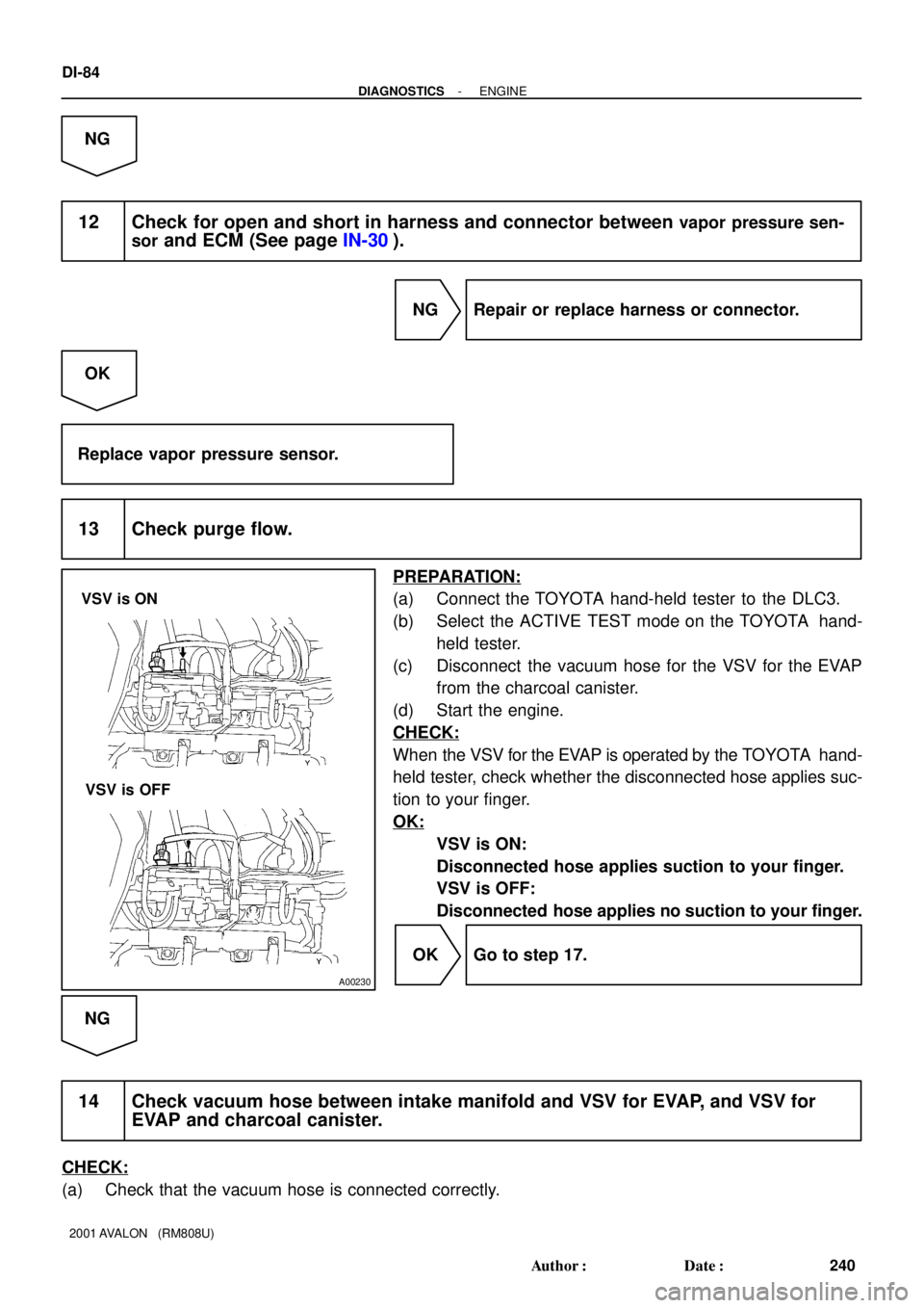
13 Check purge flow.
PREPARATION:
(a) Connect the TOYOTA hand-held tester to the DLC3.
(b) Select the ACTIVE TEST mode on the TOYOTA hand-
held tester.
(c) Disconnect the vacuum hose for the VSV for the EVAP
from the charcoal canister.
(d) Start the engine.
CHECK:
When the VSV for the EVAP is operated by the TOYOTA hand-
held tester, check whether the disconnected hose applies suc-
tion to your finger.
OK:
VSV is ON:
Disconnected hose applies suction to your finger.
VSV is OFF:
Disconnected hose applies no suction to your finger.
OK Go to step 17.
NG
14 Check vacuum hose between intake manifold and VSV for EVAP, and VSV for
EVAP and charcoal canister.
CHECK:
(a) Check that the vacuum hose is connected correctly.
Page 1278 of 1897
S05053
PCV Valve
EC04N-02
P02006Cylinder Head sideClean Hose
P02477
Intake Manifold
Side
P12931
EC-4- EMISSION CONTROLPOSITIVE CRANKCASE VENTILATION (PCV)
SYSTEM
1098 Author�: Date�:
2001 AVALON (RM808U)
POSITIVE CRANKCASE
VENTILATION (PCV) SYSTEM
INSPECTION
1. INSPECT PCV VALVE
(a) Remove the PCV valve.
(b) Install clean hose to the PCV valve.
(c) Inspect the PCV valve operation.
(1) Blow air into the cylinder head side, and check that
air passes through easily.
CAUTION:
Do not suck air through the valve.
Petroleum substances inside the valve are harmful.
(2) Blow air into the intake manifold side, and check
that air passes through with difficulty.
If operation is not as specified, replace the PCV valve.
(d) Remove clean hose from the PCV valve.
(e) Reinstall the PCV valve.
2. VISUALLY INSPECT HOSES, CONNECTIONS AND
GASKETS
Check for cracks, leaks or damage.
Page 1287 of 1897
EM-2
- ENGINE MECHANICALCO/HC
986 Author�: Date�:
2001 AVALON (RM808U)
If the CO/HC concentration does not comply with regulations,
troubleshoot in the order given below.
See the table below for possible causes, and then inspect and
correct the applicable causes if necessary.
COHCProblemsCauses
NormalHighRough idle3. Faulty ignitions:
�Incorrect timing
�Fouled, shorted or improperly gapped plugs
4. Incorrect valve clearance
5. Leaky intake and exhaust valves
6. Leaky cylinders
LowHighRough idle
(Fluctuating HC reading)1. Vacuum leaks:
�PCV hoses
�Intake manifold
�Air intake chamber
�Throttle Body
�IAC valve
�Brake booster line
2. Lean mixture causing misfire
HighHighRough idle
(Black smoke from exhaust)1. Restricted air filter
2. Plugged PCV valve
3. Faulty SFI systems:
�Faulty pressure regulator
�Defective ECT sensor
�Faulty ECM
�Faulty injectors
�Faulty throttle position sensor
�Faulty MAF meter
Page 1319 of 1897
Water Bypass Hose
A10522
PS Pressure Tube
Throttle Body Bracket
Engine WireThrottle Position
Sensor Connector
Vacuum Hose Brake Booster
39 (400,29)
IAC Valve
Connector
Accelerator Cable
Purge Hose
Hose Vacuum
�Gasket
VSV Connector for No.2 ACIS
Engine Coolant
Reservoir Hose
43 (440,32)
ECT Sender
Gauge Connector
ECT Sensor
Connector
Grand Strap
Connector
15 (150,11)
Water Outlet
15 (150,11)
Water Bypass
Hose
Upper Radiator
HoseFuel Inlet Hose
Injector Connector Intake Manifold
Assembly
�Retainer
Heater Hose
�GasketIgnition Coil
Connector
� Non-reusable part: Specified torque
N´m (kgf´cm, ft´lbf)
19.5 (200, 14)
No.1 Engine
Hanger
VSV Connector for
EVAP
Ground Cable
PCV Hose Ground Cable
Air Intake Chamber
Assembly
� Gasket
Spark PlugIgnition Coil
Ground Strap
DLC1
Gasket
Fuel Hose Clamp
VSV Connector
for No.1 ACIS
Throttle Cable
- ENGINE MECHANICALCYLINDER HEAD
EM-27
1011 Author�: Date�:
2001 AVALON (RM808U)
Page 1326 of 1897
P12755
A05231
A05227
EM0580
- ENGINE MECHANICALCYLINDER HEAD
EM-43
1027 Author�: Date�:
2001 AVALON (RM808U)
5. CLEAN VALVE GUIDE BUSHINGS
Using a valve guide bushing brush and solvent, clean all the
guide bushings.
6. INSPECT FOR FLATNESS
Using a precision straight edge and feeler gauge, measure the
surfaces contacting the cylinder block and the manifolds for
warpage.
Maximum warpage: 0.10 mm (0.0039 in.)
If warpage is greater than maximum, replace the cylinder head.
7. INSPECT FOR CRACKS
Using a dye penetrant, check the combustion chamber, intake
ports, exhaust ports and cylinder block contact surface for
cracks.
If cracked, replace the cylinder head.
8. CLEAN VALVES
(a) Using a gasket scraper, chip off any carbon from the valve
head.
(b) Using a wire brush, thoroughly clean the valve.
Page 1333 of 1897

EM3322
Free Distance
P12685
EM6368
P12400
EM-50
- ENGINE MECHANICALCYLINDER HEAD
1034 Author�: Date�:
2001 AVALON (RM808U)
(e) Under the condition of (d), turn VVT-i to the advance
angle side (the white arrow marked direction in the il-
lustration) with your hand.
(f) Except the position where the lock pin meets at the maxi-
mum delay angle, let VVT-i turn back and forth and check
the movable range and that there is no disturbance.
Standard: Movable smoothly in the range about 30°
(g) Turn VVT-i with your hand and lock it at the maximum
delay angle position.
21. INSPECT CAMSHAFT GEAR SPRING
Using vernier calipers, measure the free distance between the
spring ends.
Free distance: 18.2 - 18.8 mm (0.712 - 0.740 in.)
If the free distance is not as specified, replace the gear spring.
22. INSPECT VALVE LIFTERS AND LIFTER BORES
(a) Using a caliper gauge, measure the lifter bore diameter
of the cylinder head.
Lifter bore diameter:
31.000 - 31.018 mm (1.2205 - 1.2212 in.)
(b) Using a micrometer, measure the lifter diameter.
Lifter diameter:
30.966 - 30.976 mm (1.2191 - 1.2195 in.)
(c) Subtract the lifter diameter measurement from the lifter
bore diameter measurement.
Standard oil clearance:
0.024 - 0.050 mm (0.0009 - 0.0020 in.)
Maximum oil clearance: 0.07 mm (0.0028 in.)
If the oil clearance is greater than maximum, replace the lifter.
If necessary, replace the cylinder head.
23. INSPECT AIR INTAKE CHAMBER
Using a precision straight edge and feeler gauge, measure the
surface contacting the intake manifold for warpage.
Maximum warpage: 0.10 mm (0.0039 in.)
If warpage is greater than maximum, replace the chamber.
Page 1334 of 1897

Z09167
Cylinder Head Side
Air Intake Chamber Side
A07443
RH Side
LH Side
P12496
- ENGINE MECHANICALCYLINDER HEAD
EM-51
1035 Author�: Date�:
2001 AVALON (RM808U)
24. INSPECT INTAKE MANIFOLD
Using a precision straight edge and feeler gauge, measure the
surface contacting the cylinder head and air intake chamber for
warpage.
Maximum warpage:
Air intake chamber side0.15 mm (0.0059 in.)
Cylinder head side0.08 mm (0.0031 in.)
If warpage is greater than maximum, replace the manifold.
25. INSPECT EXHAUST MANIFOLDS
Using a precision straight edge and feeler gauge, measure the
surface contacting the cylinder head for warpage.
Maximum warpage: 0.50 mm (0.0196 in.)
If warpage is greater than maximum, replace the manifold.
26. INSPECT 12 POINTED HEAD CYLINDER HEAD
BOLTS
Using vernier calipers, measure the tension portion diameter of
the bolt.
Standard outside diameter:
8.95 - 9.05 mm (0.3524 - 0.3563 in.)
Minimum outside diameter: 8.75 mm (0.3445 in.)
If the diameter is less than minimum, replace the bolt.
Page 1344 of 1897

A07428
86
5 43 2
1
910
7
117
A09699
8 mm Hexagon Wrench
A09695
Throttle Body
Bracket
Engine
Hanger
EM-68
- ENGINE MECHANICALCYLINDER HEAD
1052 Author�: Date�:
2001 AVALON (RM808U)
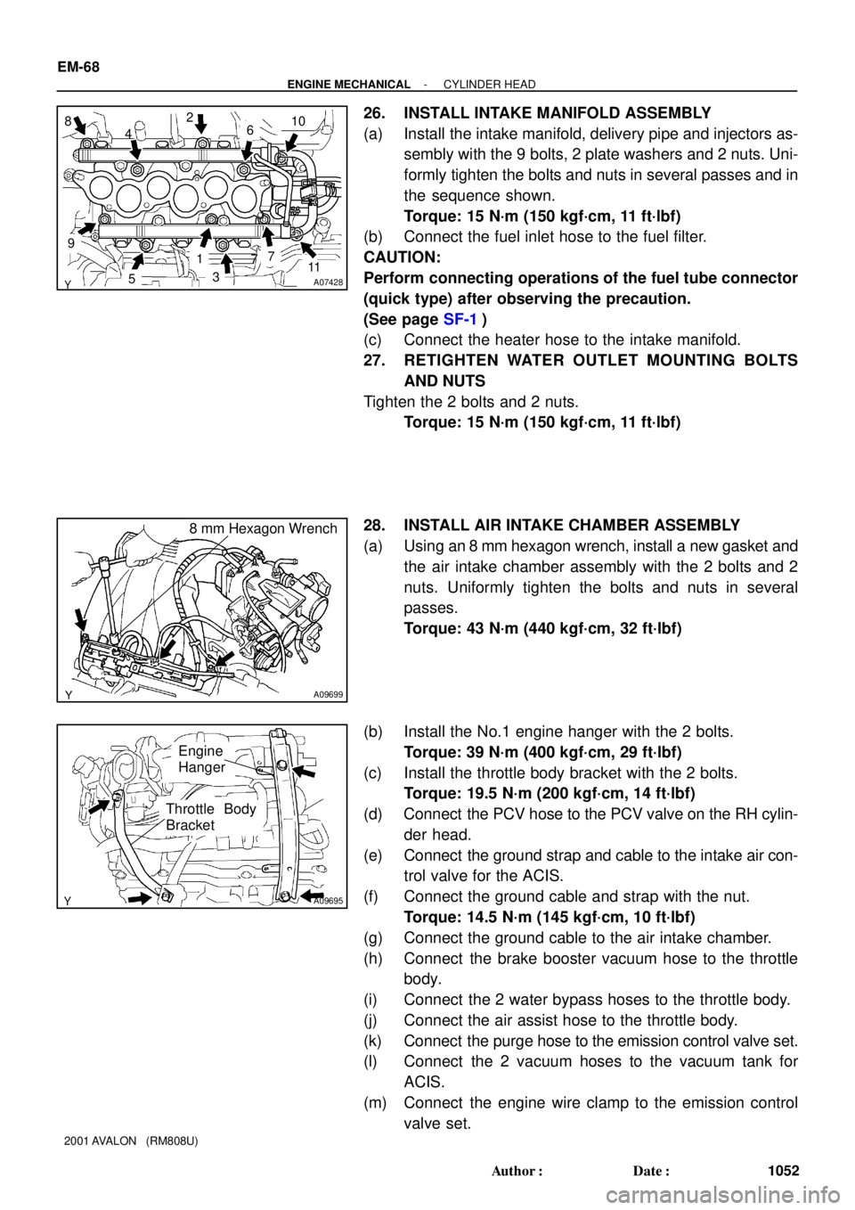
26. INSTALL INTAKE MANIFOLD ASSEMBLY
(a) Install the intake manifold, delivery pipe and injectors as-
sembly with the 9 bolts, 2 plate washers and 2 nuts. Uni-
formly tighten the bolts and nuts in several passes and in
the sequence shown.
Torque: 15 N´m (150 kgf´cm, 11 ft´lbf)
(b) Connect the fuel inlet hose to the fuel filter.
CAUTION:
Perform connecting operations of the fuel tube connector
(quick type) after observing the precaution.
(See page SF-1)
(c) Connect the heater hose to the intake manifold.
27. RETIGHTEN WATER OUTLET MOUNTING BOLTS
AND NUTS
Tighten the 2 bolts and 2 nuts.
Torque: 15 N´m (150 kgf´cm, 11 ft´lbf)
28. INSTALL AIR INTAKE CHAMBER ASSEMBLY
(a) Using an 8 mm hexagon wrench, install a new gasket and
the air intake chamber assembly with the 2 bolts and 2
nuts. Uniformly tighten the bolts and nuts in several
passes.
Torque: 43 N´m (440 kgf´cm, 32 ft´lbf)
(b) Install the No.1 engine hanger with the 2 bolts.
Torque: 39 N´m (400 kgf´cm, 29 ft´lbf)
(c) Install the throttle body bracket with the 2 bolts.
Torque: 19.5 N´m (200 kgf´cm, 14 ft´lbf)
(d) Connect the PCV hose to the PCV valve on the RH cylin-
der head.
(e) Connect the ground strap and cable to the intake air con-
trol valve for the ACIS.
(f) Connect the ground cable and strap with the nut.
Torque: 14.5 N´m (145 kgf´cm, 10 ft´lbf)
(g) Connect the ground cable to the air intake chamber.
(h) Connect the brake booster vacuum hose to the throttle
body.
(i) Connect the 2 water bypass hoses to the throttle body.
(j) Connect the air assist hose to the throttle body.
(k) Connect the purge hose to the emission control valve set.
(l) Connect the 2 vacuum hoses to the vacuum tank for
ACIS.
(m) Connect the engine wire clamp to the emission control
valve set.