Page 1567 of 1897

SS0EG-02
- SERVICE SPECIFICATIONSENGINE MECHANICAL
SS-9
125 Author�: Date�:
2001 AVALON (RM808U)
TORQUE SPECIFICATION
Part tightenedN´mkgf´cmft´lbf
Timing belt plate x Oil pump88069 in.´lbf
No.1 idler pulley x Oil pump3435025
No.2 idler pulley x No.2 idler pulley bracket4344032
Camshaft timing pulley x Camshaft
for SST125
881,300
90094
65
Timing belt tensioner x Oil pump2728020
RH engine mounting bracket x Cylinder block2829021
No.2 timing belt cover x No.3 timing belt cover8.58574 in.´lbf
No.1 timing belt cover x Oil pump8.58574 in.´lbf
Crankshaft pulley x Crankshaft2152,200159
No.2 generator bracket x Engine RH mounting bracket2829021
Cylinder head x Cylinder block 12 pointed head 1st
2nd
Recessed head54
Turn 90°
18.5550
Turn 90°
18540
Turn 90°
13
Camshaft bearing cap x Cylinder head1616012
Cylinder head cover x Cylinder head88069 in.´lbf
Exhaust manifold x Cylinder head4950036
Exhaust manifold stay x Exhaust manifold California
Except California34
20350
20025
15
Exhaust manifold stay x Transmission housing California
Except California34
20350
20025
15
No.1 EGR pipe x RH exhaust manifold121209
No.1 EGR pipe x EGR cooler121209
PS pump bracket x RH cylinder head4344032
Oil dipstick guide x LH cylinder head88069 in.´lbf
Water inlet pipe x LH cylinder head19.520014
Cylinder head rear plate x LH cylinder head88069 in.´lbf
No.3 timing belt cover x Cylinder head8.58574 in.´lbf
Water outlet x Intake manifold1515011
Fuel inlet hose x Fuel filter2930021
Intake manifold x Cylinder head1515011
Air intake chamber x Intake manifold4344032
No.2 EGR pipe x Air intake chamber121209
No.2 EGR pipe x EGR cooler121209
No.1 engine hanger x Air intake chamber3940029
No.1 engine hanger x RH cylinder head3940029
Air intake chamber stay x Air intake chamber19.520014
Air intake chamber stay x RH cylinder head19.520014
Main bearing cap x Cylinder block 12 pointed head 1st
2nd
6 pointed head22
Turn 90°
27225
Turn 90°
27516
Turn 90°
20
Connecting rod cap x Connecting rod 1st
2nd24.5
Turn 90°250
Turn 90°18
Turn 90°
Rear oil seal retainer x Cylinder block88069 in.´lbf
EGR cooler x Cylinder block99078 in.´lbf
Page 1580 of 1897
SS0EK-02
- SERVICE SPECIFICATIONSSFI
SS-13
129 Author�: Date�:
2001 AVALON (RM808U)
TORQUE SPECIFICATION
Part tightenedN´mkgf´cmft´lbf
Fuel line (Union bolt type)2930021
Fuel line (Flare nut type) using SST2828521
Fuel pump assembly x Fuel tank44035 in.´lbf
Fuel filter x Fuel pump bracket2.02017 in.´lbf
Fuel pressure regulator x Fuel pump bracket2.02017 in.´lbf
Delivery pipe x Intake manifold101007
No.1 fuel pipe x Intake manifold19.520014
Fuel tank band x Body3940029
Throttle body x Throttle body bracket19.520014
Throttle body x Air intake chamber19.520014
Throttle body x No.1 intake air control valve6.97061 in.´lbf
Camshaft timing oil control valve x Cylinder head7.58066 in.´lbf
No.2 intake air control valve x Air intake chamber14.514510
ECT sensor x Water outlet2020014
Knock sensor x Cylinder block3940029
A/F sensor x Exhaust manifold4444032
Heated oxygen sensor x Exhaust pipe4444031
Page 1635 of 1897

SF076-05
B06484
New Insulator
New
O-Ring
New GrommetNew
O-Ring
B06485
Turn
Connector
Push
S04510
Spacer
Spacer
B06614
B06616
Rotate
Outward
- SFIINJECTOR
SF-25
1134 Author�: Date�:
2001 AVALON (RM808U)
INSTALLATION
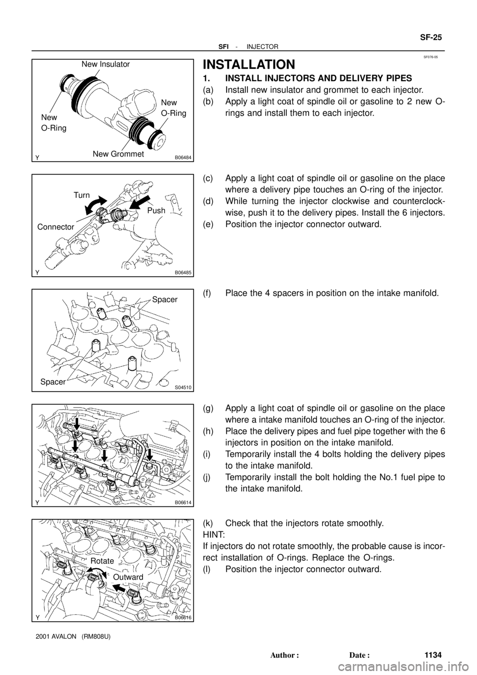
1. INSTALL INJECTORS AND DELIVERY PIPES
(a) Install new insulator and grommet to each injector.
(b) Apply a light coat of spindle oil or gasoline to 2 new O-
rings and install them to each injector.
(c) Apply a light coat of spindle oil or gasoline on the place
where a delivery pipe touches an O-ring of the injector.
(d) While turning the injector clockwise and counterclock-
wise, push it to the delivery pipes. Install the 6 injectors.
(e) Position the injector connector outward.
(f) Place the 4 spacers in position on the intake manifold.
(g) Apply a light coat of spindle oil or gasoline on the place
where a intake manifold touches an O-ring of the injector.
(h) Place the delivery pipes and fuel pipe together with the 6
injectors in position on the intake manifold.
(i) Temporarily install the 4 bolts holding the delivery pipes
to the intake manifold.
(j) Temporarily install the bolt holding the No.1 fuel pipe to
the intake manifold.
(k) Check that the injectors rotate smoothly.
HINT:
If injectors do not rotate smoothly, the probable cause is incor-
rect installation of O-rings. Replace the O-rings.
(l) Position the injector connector outward.
Page 1636 of 1897

B01020
B06618
Align
B09079
B09076
Fuel Hose
Clamp
B06613
SF-26
- SFIINJECTOR
1135 Author�: Date�:
2001 AVALON (RM808U)
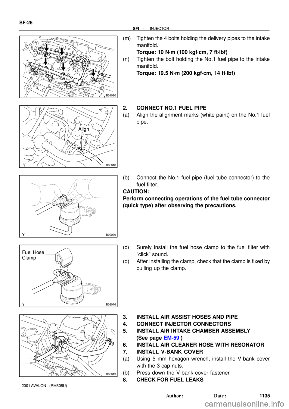
(m) Tighten the 4 bolts holding the delivery pipes to the intake
manifold.
Torque: 10 N´m (100 kgf´cm, 7 ft´lbf)
(n) Tighten the bolt holding the No.1 fuel pipe to the intake
manifold.
Torque: 19.5 N´m (200 kgf´cm, 14 ft´lbf)
2. CONNECT NO.1 FUEL PIPE
(a) Align the alignment marks (white paint) on the No.1 fuel
pipe.
(b) Connect the No.1 fuel pipe (fuel tube connector) to the
fuel filter.
CAUTION:
Perform connecting operations of the fuel tube connector
(quick type) after observing the precautions.
(c) Surely install the fuel hose clamp to the fuel filter with
ºclickº sound.
(d) After installing the clamp, check that the clamp is fixed by
pulling up the clamp.
3. INSTALL AIR ASSIST HOSES AND PIPE
4. CONNECT INJECTOR CONNECTORS
5. INSTALL AIR INTAKE CHAMBER ASSEMBLY
(See page EM-59)
6. INSTALL AIR CLEANER HOSE WITH RESONATOR
7. INSTALL V-BANK COVER
(a) Using 5 mm hexagon wrench, install the V-bank cover
with the 3 cap nuts.
(b) Press down the V-bank cover fastener.
8. CHECK FOR FUEL LEAKS
Page 1639 of 1897
B06617
SF-22
- SFIINJECTOR
1131 Author�: Date�:
2001 AVALON (RM808U)
7. REMOVE DELIVERY PIPES AND INJECTORS
NOTICE:
�Be careful not to drop the injectors when removing
the delivery pipes.
�Pay attention to put any hung load on the injector to
and from the side direction.
(a) Remove the 5 bolts and delivery pipes together with the
6 injectors and No.1 fuel pipe.
(b) Remove the 4 spacers from the intake manifold.
(c) Pull out the 6 injectors from the delivery pipes.
(d) Remove the 2 O-rings and 2 grommets from each injec-
tor.
Page 1640 of 1897
SF06S-03
B09135
Ground Cable
PCV Hose
Air Intake Chamber
Assembly
ECT Sensor
Connector ECT Sender
Gauge Connector
IAC Valve
Connector
VSV Connector for No.2 ACIS
Engine Coolant
Reservoir HoseThrottle Position
Sensor Connector Brake Booster
Vacuum Hose Throttle Body Bracket
Water Outlet PS Pressure Tube
19.5 (200, 14)
39 (400, 19)
15 (150, 11)
43 (440, 32)
Ground Strap
DLC1�Gasket
15 (150, 11)
Grand Strap
Connector
�Gasket
39 (400, 29)
V-Bank Cover
Accelerator CableAir Cleaner Hose
w/ Resonator
Purge Hose
Vacuum Hose
Fuel Hose
Clamp
Heater Hose
Intake Manifold Assembly
Injector Connector x 9
Knock Sensor
Connector
Upper Radiator
Hose
�Gasket
: Specified torque
�Non-reusable part
N´m (kgf´cm, ft´lbf)
�Retainer
Knock Sensor
Water Bypass
Hose
VSV Connector for
EVAP
No.1 Engine
Hanger
VSV Connector
for No.1 ACIS
Throttle Cable
Ground Cable
SF-76
- SFIKNOCK SENSOR
1185 Author�: Date�:
2001 AVALON (RM808U)
KNOCK SENSOR
COMPONENTS
Page 1641 of 1897

SF102-02
A10518
5 mm
Hexagon
Wrench
P20115
SSTKnock Sensor 1
Knock Sensor 2
P01630
Ohmmeter
- SFIKNOCK SENSOR
SF-77
1186 Author�: Date�:
2001 AVALON (RM808U)
INSPECTION
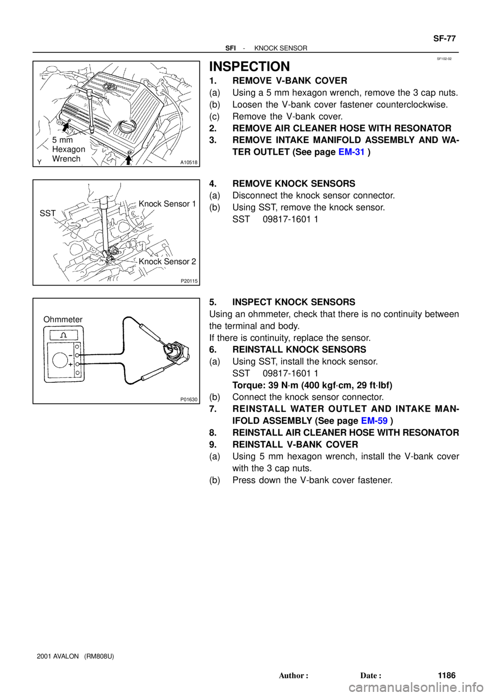
1. REMOVE V-BANK COVER
(a) Using a 5 mm hexagon wrench, remove the 3 cap nuts.
(b) Loosen the V-bank cover fastener counterclockwise.
(c) Remove the V-bank cover.
2. REMOVE AIR CLEANER HOSE WITH RESONATOR
3. REMOVE INTAKE MANIFOLD ASSEMBLY AND WA-
TER OUTLET (See page EM-31)
4. REMOVE KNOCK SENSORS
(a) Disconnect the knock sensor connector.
(b) Using SST, remove the knock sensor.
SST 09817-1601 1
5. INSPECT KNOCK SENSORS
Using an ohmmeter, check that there is no continuity between
the terminal and body.
If there is continuity, replace the sensor.
6. REINSTALL KNOCK SENSORS
(a) Using SST, install the knock sensor.
SST 09817-1601 1
Torque: 39 N´m (400 kgf´cm, 29 ft´lbf)
(b) Connect the knock sensor connector.
7. REINSTALL WATER OUTLET AND INTAKE MAN-
IFOLD ASSEMBLY (See page EM-59)
8. REINSTALL AIR CLEANER HOSE WITH RESONATOR
9. REINSTALL V-BANK COVER
(a) Using 5 mm hexagon wrench, install the V-bank cover
with the 3 cap nuts.
(b) Press down the V-bank cover fastener.
Page 1648 of 1897

S05054
New Gasket
FI1654
Fulcrum Length
30 cm
SST
FI6372
CORRECT New O-Ring
Delivery Pipe
Injector Grommet
WRONG
B05295
O-Ring
Grommet
Spacer InsulatorDelivery Pipe
O-Ring
- SFISFI SYSTEM
SF-3
111 2 Author�: Date�:
2001 AVALON (RM808U)
(b) When connecting the union bolt on the high pressure pipe
union, observe the following procedures:
(1) Always use 2 new gaskets.
(2) Tighten the union bolt by hand.
(3) Tighten the union bolt to the specified torque.
Torque: 29 N´m (300 kgf´cm, 21 ft´lbf)
(c) When connecting the flare nut on the high pressure pipe
union, observe the following procedures:
(1) Apply a light coat of engine oil to the flare nut, and
tighten the flare nut by hand.
(2) Using SST, tighten the flare nut to specified torque.
SST 09023-12700
NOTICE:
Do not rotate the fuel pipe, when tightening the flare nut.
Torque: 28 N´m (285 kgf´cm, 21 ft´lbf)
HINT:
Use a torque wrench with a fulcrum length of 30 cm (11.81 in.).
(d) Observe the following precautions when removing and
installing the injectors.
(1) Never reuse the O-ring.
(2) When placing a new O-ring on the injector, take
care not to damage it in any way.
(3) Coat a new O-ring with spindle oil or gasoline be-
fore installing-never use engine, gear or brake oil.
(e) Install the injector to the delivery pipe and intake manifold
as shown in the illustration.
(f) Observe these precautions when disconnecting the fuel
tube connector (quick type).
(1) Check if there is any dirt like mud on the pipe and
around the connector before disconnecting them
and clean the dirt away.
(2) Be sure to disconnect with hands.