Page 1459 of 1897

(d) Engage the spline teeth of the oil pump drive gear with th")
B04146
B04147
AB
Seal Width
3 - 4 mmAB Region ºYº Region ºXº LU-16
- LUBRICATIONOIL PUMP
1241 Author�: Date�:
2001 AVALON (RM808U)
(d) Engage the spline teeth of the oil pump drive gear with the
large teeth of the crankshaft, and slide the oil pump on the
crankshaft.
(e) Install the oil pump with the 9 bolts. Uniformly tighten the
bolts in several passes.
Torque:
10 mm head: 8 N´m (80 kgf´cm, 69 in.´lbf)
12 mm head: 19.5 N´m (200 kgf´cm, 14 ft´lbf)
2. INSTALL CRANKSHAFT POSITION SENSOR
Torque: 8 N´m (80 kgf´cm, 69 in.´lbf)
3. INSTALL BAFFLE PLATE TO NO.1 OIL PAN
Torque: 8 N´m (80 kgf´cm, 69 in.´lbf)
4. INSTALL NO.1 OIL PAN
(a) Remove any old packing (FIPG) material and be careful
not to drop any oil on the contact surfaces of the oil pan,
oil pump and cylinder block.
�Using a razor blade and gasket scraper, remove all
the old packing (FIPG) material from the gasket sur-
faces and sealing grooves.
�Thoroughly clean all components to remove all the
loose material.
�Using a non-residue solvent, clean both sealing
surfaces.
(b) Apply seal packing to the oil pan as shown in the illustra-
tion.
Seal packing: Part No. 08826-00080 or equivalent
Region ºXº is at the outer side of the bolt hole.
Region ºYº is at the inner side of the bolt hole.
�Install a nozzle that has been cut to a or 3 - 4 mm
(0.12 - 0.16 in.) opening.
HINT:
Avoid applying an excessive amount to the surface.
�Parts must be assembled within 3 minutes of ap-
plication. Otherwise the material must be removed
and reapplied.
�Immediately remove nozzle from the tube and rein-
stall cap.
(c) Install the oil pan with the 17 bolts and 2 nuts. Uniformly
tighten the bolts and nuts in several passes.
Torque:
10 mm head: 8 N´m (80 kgf´cm, 69 in.´lbf)
12 mm head: 19.5 N´m (200 kgf´cm, 14 ft´lbf)
14 mm head: 37.2 N´m (380 kgf´cm, 27 ft´lbf)
Page 1460 of 1897

(d) Install the No.1 exhaust pipe support bracket with the 2
bolts.
Torque: 7.8 N´m (80 kgf´")
P12568
AB
Seal Width
4 - 5 mm A
B
- LUBRICATIONOIL PUMP
LU-17
1242 Author�: Date�:
2001 AVALON (RM808U)
(d) Install the No.1 exhaust pipe support bracket with the 2
bolts.
Torque: 7.8 N´m (80 kgf´cm, 69 in.´lbf)
5. INSTALL OIL STRAINER
Install a new gasket and the oil strainer with the bolt and 2 nuts.
Torque: 8 N´m (80 kgf´cm, 69 in.´lbf)
6. INSTALL NO.2 OIL PAN
(a) Remove any old packing (FIPG) material and be careful
not to drop any oil on the contact surface of the No.1 and
No.2 oil pans.
�Using a razor blade and gasket scraper, remove all
the old packing (FIPG) material from the gasket sur-
faces and sealing grooves.
�Thoroughly clean all components to remove all the
loose material.
�Using a non-residue solvent, clean both sealing
surfaces.
NOTICE:
Do not use a solvent which will affect the painted surfaces.
(b) Apply seal packing to the No.2 oil pan as shown in the il-
lustration.
Seal packing: Part No. 08826-00080 or equivalent
�Install a nozzle that has been cut to a 4 - 5 mm (0.16
- 0.20 in.) opening.
HINT:
Avoid applying an excessive amount to the surface.
�Parts must be assembled within 3 minutes of ap-
plication. Otherwise the material must be removed
and reapplied.
�Immediately remove nozzle from the tube and rein-
stall cap.
(c) Install the No.2 oil pan with the 10 bolts and 2 nuts. Uni-
formly tighten the bolts and nuts in several passes.
Torque: 8 N´m (80 kgf´cm, 69 in.´lbf)
7. INSTALL TIMING PULLEYS (See page EM-21)
8. INSTALL TIMING BELT (See page EM-21)
Page 1461 of 1897
LU-18
- LUBRICATIONOIL PUMP
1243 Author�: Date�:
2001 AVALON (RM808U)
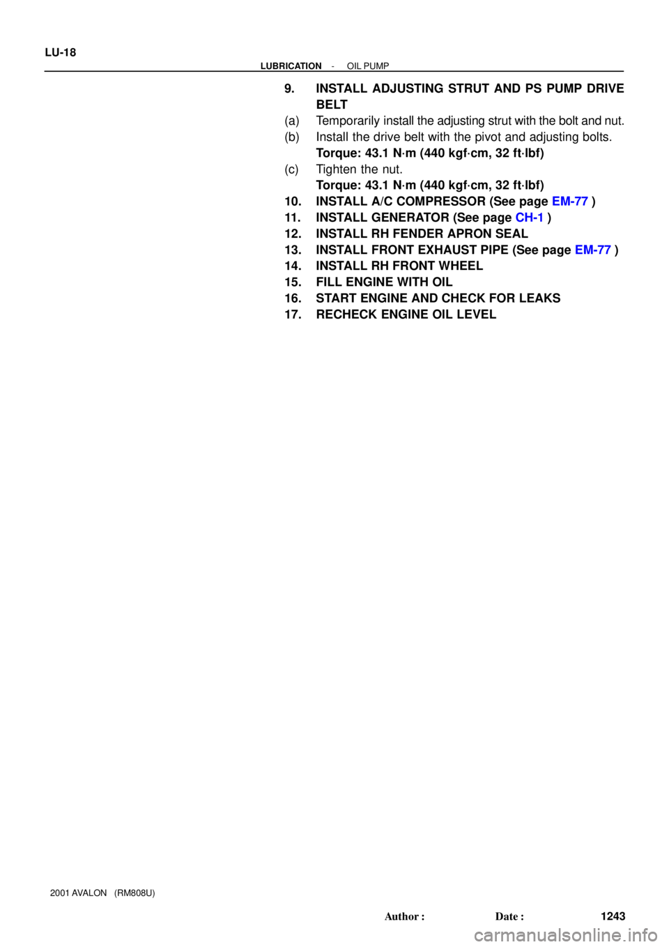
9. INSTALL ADJUSTING STRUT AND PS PUMP DRIVE
BELT
(a) Temporarily install the adjusting strut with the bolt and nut.
(b) Install the drive belt with the pivot and adjusting bolts.
Torque: 43.1 N´m (440 kgf´cm, 32 ft´lbf)
(c) Tighten the nut.
Torque: 43.1 N´m (440 kgf´cm, 32 ft´lbf)
10. INSTALL A/C COMPRESSOR (See page EM-77)
11. INSTALL GENERATOR (See page CH-1)
12. INSTALL RH FENDER APRON SEAL
13. INSTALL FRONT EXHAUST PIPE (See page EM-77)
14. INSTALL RH FRONT WHEEL
15. FILL ENGINE WITH OIL
16. START ENGINE AND CHECK FOR LEAKS
17. RECHECK ENGINE OIL LEVEL
Page 1462 of 1897
LU01W-03
B04141
Mark
LU-14
- LUBRICATIONOIL PUMP
1239 Author�: Date�:
2001 AVALON (RM808U)
REASSEMBLY
1. INSTALL DRIVE AND DRIVEN ROTORS
(a) Place the drive and driven rotors into pump body with the
marks facing the pump body cover side.
(b) Install the pump body cover with the 10 screws.
2. INSTALL RELIEF VALVE
Insert the relief valve and spring into the pump body hole, and
install the plug.
Torque: 49.1 N´m (500 kgf´cm, 36 ft´lbf)
Page 1463 of 1897
LU0IB-01
P18778
Pivot
Bolt
Adjusting
Strut
Adjusting Bolt
B04135
P18801
- LUBRICATIONOIL PUMP
LU-9
1234 Author�: Date�:
2001 AVALON (RM808U)
REMOVAL
HINT:
When repairing the oil pump, the oil pan and strainer should be
removed and cleaned.
1. DRAIN ENGINE OIL
2. REMOVE RH FRONT WHEEL
3. REMOVE RH FENDER APRON SEAL
4. REMOVE FRONT EXHAUST PIPE
(See page EM-72)
5. REMOVE GENERATOR FROM ENGINE
(See page CH-6)
6. REMOVE A/C COMPRESSOR FROM ENGINE
(See page EM-72)
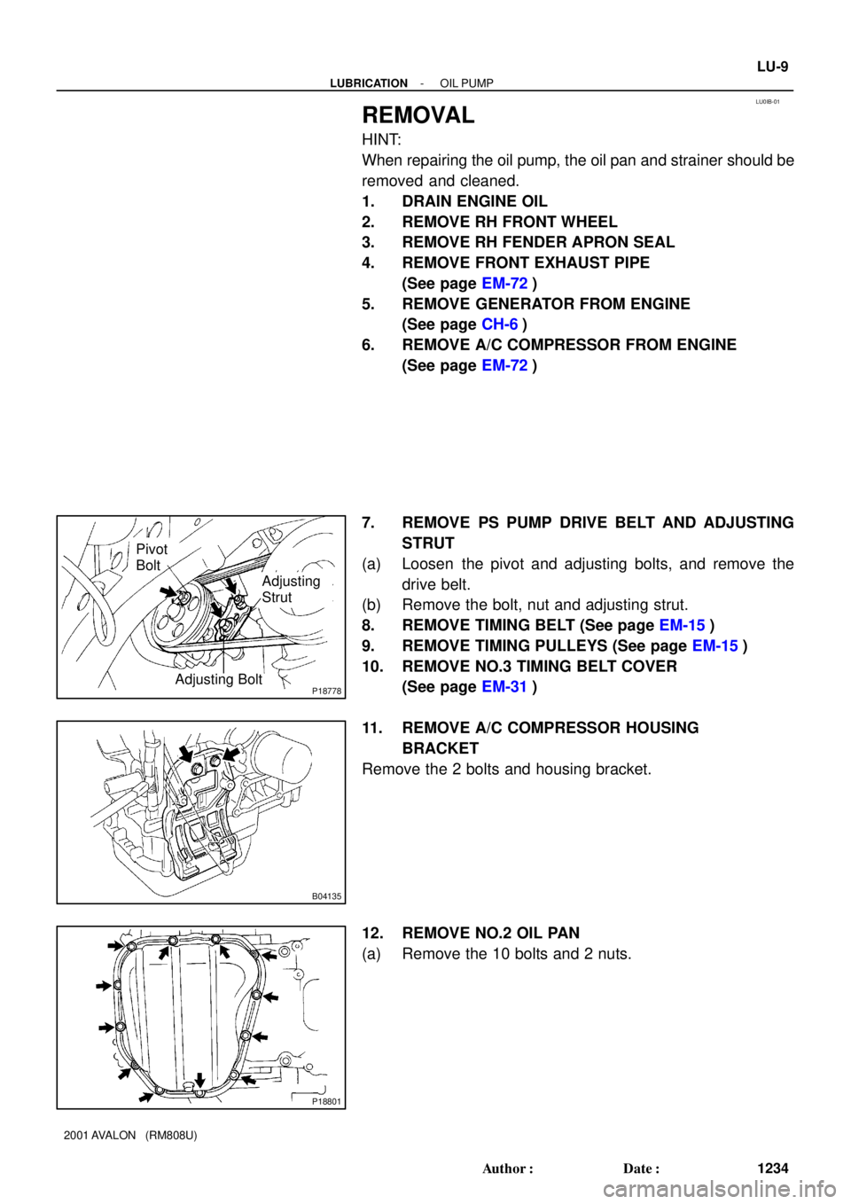
7. REMOVE PS PUMP DRIVE BELT AND ADJUSTING
STRUT
(a) Loosen the pivot and adjusting bolts, and remove the
drive belt.
(b) Remove the bolt, nut and adjusting strut.
8. REMOVE TIMING BELT (See page EM-15)
9. REMOVE TIMING PULLEYS (See page EM-15)
10. REMOVE NO.3 TIMING BELT COVER
(See page EM-31)
11. REMOVE A/C COMPRESSOR HOUSING
BRACKET
Remove the 2 bolts and housing bracket.
12. REMOVE NO.2 OIL PAN
(a) Remove the 10 bolts and 2 nuts.
Page 1464 of 1897

(b) Insert the blade of SST between the No.1 and No.2 oil
pans, and cut off applied")
P12716SSTSST
P18802
B04136
B04137
P20050Pry LU-10
- LUBRICATIONOIL PUMP
1235 Author�: Date�:
2001 AVALON (RM808U)
(b) Insert the blade of SST between the No.1 and No.2 oil
pans, and cut off applied sealer and remove the No.1 oil
pan.
SST 09032-00100
NOTICE:
�Be careful not to the damage the No.2 oil pan contact
surface of the No.1 oil pan.
�Be careful not to damage the No.2 oil pan flange.
13. REMOVE OIL STRAINER
Remove the bolt, 2 nuts, oil strainer and gasket.
14. REMOVE NO.1 OIL PAN
(a) Remove the 2 bolts and No.1 exhaust pipe support brack-
et.
(b) Remove the 17 bolts and 2 nuts.
(c) Using a screwdriver, remove the oil pan by prying the por-
tions between the cylinder block and oil pan.
NOTICE:
Be careful not to damage the contact surfaces of the cylin-
der block and oil pan.
15. REMOVE BAFFLE PLATE FROM NO.1 OIL PAN
16. REMOVE CRANKSHAFT POSITION SENSOR
17. REMOVE OIL PUMP
(a) Remove the 9 bolts.
(b) Remove the oil pump by prying a screwdriver between the
oil pump and main bearing cap.
(c) Remove the O-ring.
Page 1465 of 1897
LU01V-03
P12413
P12392
SST
P12475
Cut Position
P12473
SST
- LUBRICATIONOIL PUMP
LU-13
1238 Author�: Date�:
2001 AVALON (RM808U)
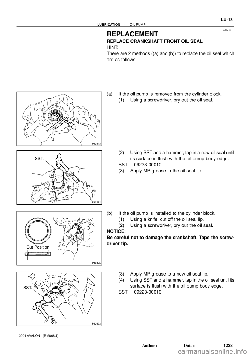
REPLACEMENT
REPLACE CRANKSHAFT FRONT OIL SEAL
HINT:
There are 2 methods ((a) and (b)) to replace the oil seal which
are as follows:
(a) If the oil pump is removed from the cylinder block.
(1) Using a screwdriver, pry out the oil seal.
(2) Using SST and a hammer, tap in a new oil seal until
its surface is flush with the oil pump body edge.
SST 09223-00010
(3) Apply MP grease to the oil seal lip.
(b) If the oil pump is installed to the cylinder block.
(1) Using a knife, cut off the oil seal lip.
(2) Using a screwdriver, pry out the oil seal.
NOTICE:
Be careful not to damage the crankshaft. Tape the screw-
driver tip.
(3) Apply MP grease to a new oil seal lip.
(4) Using SST and a hammer, tap in the oil seal until its
surface is flush with the oil pump body edge.
SST 09223-00010
Page 1468 of 1897

CHASSIS
INSPECTION
1. INSPECT STEERING LINKAGE
(a) Check the steering wheel free-play (See page SR-8).
(b) Check the")
MA01O-02
B08915
- MAINTENANCECHASSIS
MA-7
49 Author�: Date�:
2001 AVALON (RM808U)
CHASSIS
INSPECTION
1. INSPECT STEERING LINKAGE
(a) Check the steering wheel free-play (See page SR-8).
(b) Check the steering linkage for looseness or damage.
Check that:
�Tie rod ends do not have excessive play.
�Dust seals and boots are not damaged.
�Boot clamps are not loose.
2. INSPECT SRS AIRBAG (See pages RS-15, RS-30)
3. INSPECT STEERING GEAR HOUSING OIL
Check the steering gear housing for oil leakage.
4. INSPECT DRIVE SHAFT BOOTS
Check the drive shaft boots for clamp looseness, leakage or
damage.
5. INSPECT BALL JOINTS AND DUST COVERS
(a) Inspect the ball joints for excessive looseness.
�Jack up the front of the vehicle and place wooden
blocks with a height of 180 - 200 mm (7.09 - 7.87
in.) under the front tires.
�Lower the jack until there is about half a load on the
front coil spring. Place stands under the vehicle for
safety.
�Check that the front wheels are pointing straight
ahead, and block them with chocks.
�Using a lever, pry up the end of the lower arm, and
check the amount of play.
Maximum ball joint vertical play: 0 mm (0 in.)
If there is play, replace the ball joint.
(b) Check the dust cover for damage.
6. CHECK TRANSAXLE FLUID
Visually check the transaxle for fluid leakage.
If leakage is found, check for the cause and repair.
7. REPLACE TRANSAXLE FLUID (See page DI-160)