Page 1354 of 1897

A05195
IntakeMain Gear
Sub-Gear
Service Bolt
A05207
Intake
7
8
5
6
3
41 2
9
10
A05197
7
85
6
3
41
2
9
10 Exhaust EM-36
- ENGINE MECHANICALCYLINDER HEAD
1020 Author�: Date�:
2001 AVALON (RM808U)
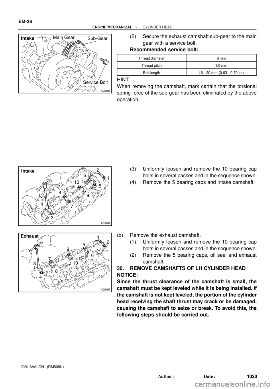
(2) Secure the exhaust camshaft sub-gear to the main
gear with a service bolt.
Recommended service bolt:
Thread diameter6 mm
Thread pitch1.0 mm
Bolt length16 - 20 mm (0.63 - 0.79 in.)
HINT:
When removing the camshaft, mark certain that the torsional
spring force of the sub-gear has been eliminated by the above
operation.
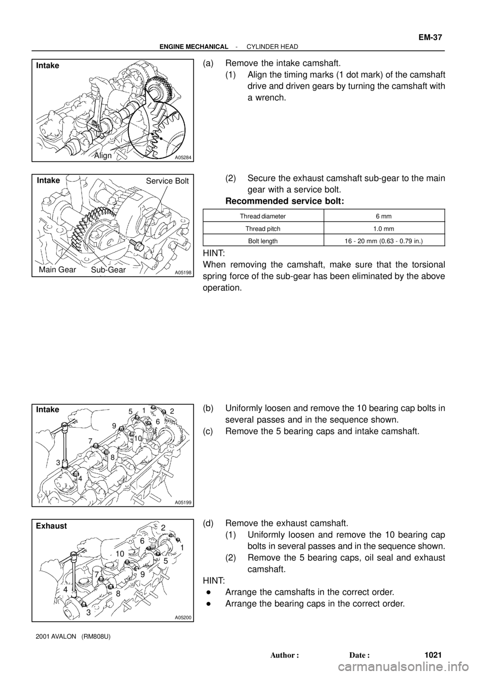
(3) Uniformly loosen and remove the 10 bearing cap
bolts in several passes and in the sequence shown.
(4) Remove the 5 bearing caps and intake camshaft.
(b) Remove the exhaust camshaft.
(1) Uniformly loosen and remove the 10 bearing cap
bolts in several passes and in the sequence shown.
(2) Remove the 5 bearing caps, oil seal and exhaust
camshaft.
30. REMOVE CAMSHAFTS OF LH CYLINDER HEAD
NOTICE:
Since the thrust clearance of the camshaft is small, the
camshaft must be kept leveled while it is being installed. If
the camshaft is not kept leveled, the portion of the cylinder
head receiving the shaft thrust may crack or be damaged,
causing the camshaft to seize or break. To avoid this, the
following steps should be carried out.
Page 1355 of 1897

A05284Align Intake
A05198
Intake
Main GearSub-GearService Bolt
A05199
Intake
7
85
6
3
4
1
2
9
10
A05200
7
8
5
6
3
4
1
2
9
10 Exhaust
- ENGINE MECHANICALCYLINDER HEAD
EM-37
1021 Author�: Date�:
2001 AVALON (RM808U)
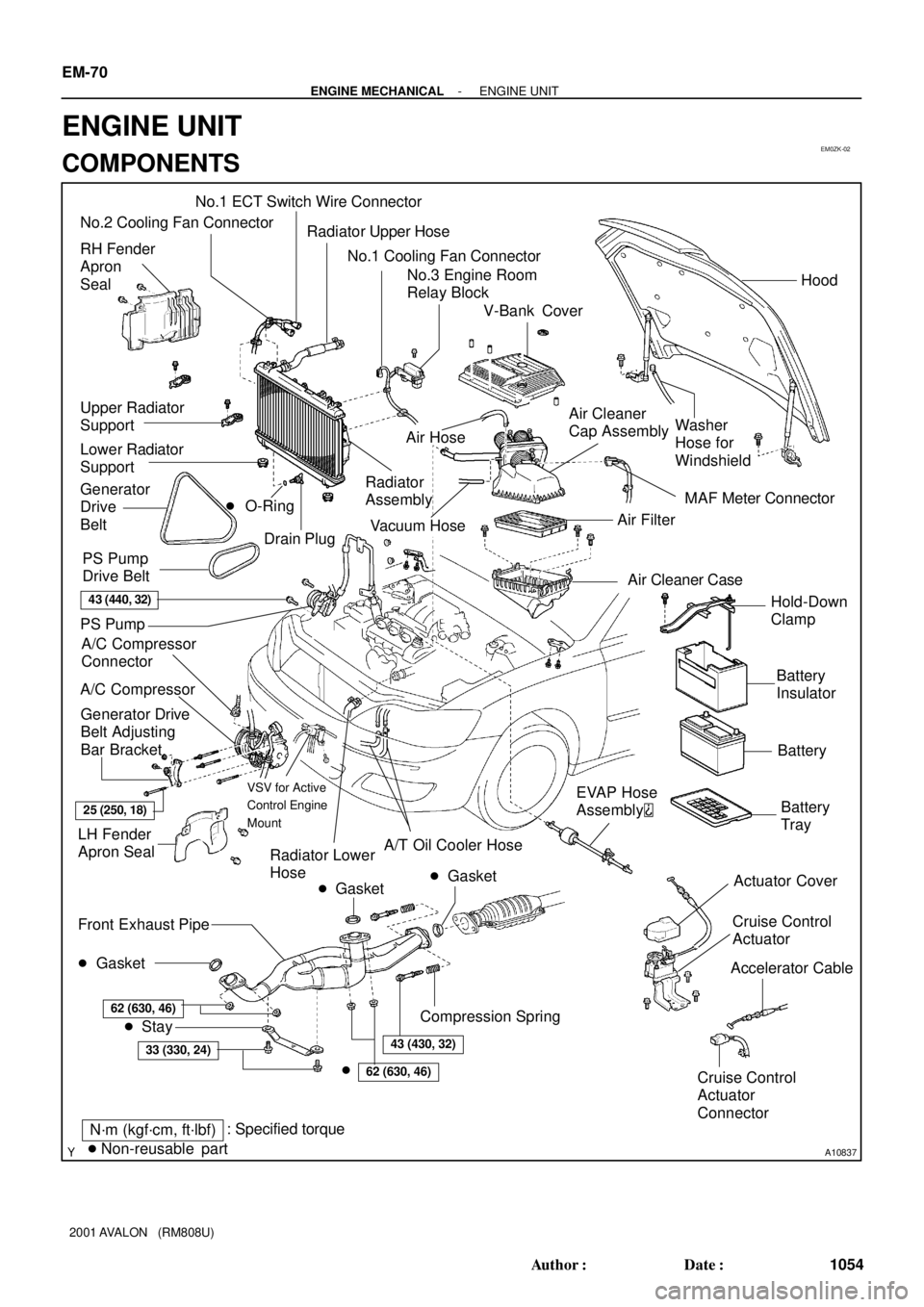
(a) Remove the intake camshaft.
(1) Align the timing marks (1 dot mark) of the camshaft
drive and driven gears by turning the camshaft with
a wrench.
(2) Secure the exhaust camshaft sub-gear to the main
gear with a service bolt.
Recommended service bolt:
Thread diameter6 mm
Thread pitch1.0 mm
Bolt length16 - 20 mm (0.63 - 0.79 in.)
HINT:
When removing the camshaft, make sure that the torsional
spring force of the sub-gear has been eliminated by the above
operation.
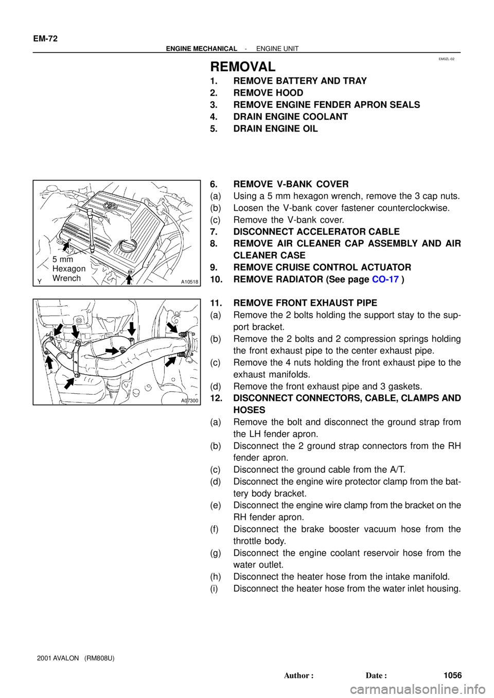
(b) Uniformly loosen and remove the 10 bearing cap bolts in
several passes and in the sequence shown.
(c) Remove the 5 bearing caps and intake camshaft.
(d) Remove the exhaust camshaft.
(1) Uniformly loosen and remove the 10 bearing cap
bolts in several passes and in the sequence shown.
(2) Remove the 5 bearing caps, oil seal and exhaust
camshaft.
HINT:
�Arrange the camshafts in the correct order.
�Arrange the bearing caps in the correct order.
Page 1360 of 1897

A05706
Align
A05738
A05245
A05243
EM-54
- ENGINE MECHANICALCYLINDER HEAD
1038 Author�: Date�:
2001 AVALON (RM808U)
(d) Align the knock pin and knock pin groove and install VVT-
i on the camshaft.
NOTICE:
Install it under the condition that the lock pin is operated
and lock at the maximum delay angle position.
(e) Apply the engine oil on the nut, the placing surface of
VVT-i and the screw portion.
HINT:
Be sure to apply the oil, otherwise the prescribed torque cannot
be obtained.
(f) Using a 46 mm socket wrench, install and torque a new
lock nut by turning it counterclockwise.
Torque: 150 N´m (1,530 kgf´cm, 110 ft´lbf)
NOTICE:
�Must change the nuts to the new ones when to change
VVT-i.
�The lock nut have LH threads.
�Never use any tool other than the socket wrench,
otherwise that may result in deforming the cam angle
rotor portion.
3. REPLACE SPARK PLUG TUBE GASKETS
(a) Bend up the tab on the ventilation baffle plate which pre-
vents the gasket from the slipping out.
(b) Using a screwdriver and hammer, tap out the gasket.
(c) Using needle-nose pliers, pry out the gasket.
Page 1362 of 1897

EM0ZK-02
A10837
No.2 Cooling Fan Connector
Upper Radiator
Support
Radiator
Assembly RH Fender
Apron
Seal
Generator
Drive
Belt
A/C Compressor
Connector
Battery
Insulator
Battery
Battery
Tray Generator Drive
Belt Adjusting
Bar Bracket
LH Fender
Apron Seal
� Gasket A/C Compressor
43 (440, 32)
25 (250, 18)
�Non-reusable partStay
N´m (kgf´cm, ft´lbf) Front Exhaust Pipe: Specified torque� Gasket
62 (630, 46)
33 (330, 24)
�
62 (630, 46)
43 (430, 32)
� Gasket
Actuator Cover No.3 Engine Room
Relay BlockHood
Hold-Down
Clamp
Washer
Hose for
Windshield
Air Filter
Air Cleaner Case � O-Ring
Drain Plug Lower Radiator
SupportAir Cleaner
Cap Assembly Radiator Upper Hose
Cruise Control
Actuator
Cruise Control
Actuator
ConnectorAccelerator Cable
PS Pump
� PS Pump
Drive Belt
Compression Spring
V-Bank Cover
A/T Oil Cooler Hose
Radiator Lower
HoseEVAP Hose
Assembly
MAF Meter Connector
VSV for Active
Control Engine
Mount
No.1 ECT Switch Wire Connector
No.1 Cooling Fan Connector
Vacuum Hose
Air Hose
EM-70
- ENGINE MECHANICALENGINE UNIT
1054 Author�: Date�:
2001 AVALON (RM808U)
ENGINE UNIT
COMPONENTS
Page 1368 of 1897
EM-80
- ENGINE MECHANICALENGINE UNIT
1064 Author�: Date�:
2001 AVALON (RM808U)
(d) Install the support stay with the 2 bolts.
Torque: 33 N´m (330 kgf´cm, 24 ft´lbf)
18. INSTALL RADIATOR (See page CO-22)
19. INSTALL CRUISE CONTROL ACTUATOR
20. INSTALL AIR CLEANER CAP ASSEMBLY AND AIR
CLEANER CASE
21. CONNECT ACCELERATOR CABLE
22. INSTALL V-BANK COVER
(a) Using a 5 mm hexagon wrench, install the V-bank cover
with the 3 cap nuts.
(b) Press down the V-bank cover fastener.
23. INSTALL ENGINE FENDER APRON SEALS
24. INSTALL BATTERY TRAY AND BATTERY
25. INSTALL HOOD
26. FILL ENGINE WITH OIL
27. FILL WITH ENGINE COOLANT
28. START ENGINE AND CHECK FOR LEAKS
29. PERFORM ROAD TEST
Check for abnormal noise, shock, slippage, correct shift points
and smooth operation.
30. RECHECK ENGINE COOLANT AND OIL LEVELS
Page 1369 of 1897

EM0ZL-02
A10518
5 mm
Hexagon
Wrench
A07300
EM-72
- ENGINE MECHANICALENGINE UNIT
1056 Author�: Date�:
2001 AVALON (RM808U)
REMOVAL
1. REMOVE BATTERY AND TRAY
2. REMOVE HOOD
3. REMOVE ENGINE FENDER APRON SEALS
4. DRAIN ENGINE COOLANT
5. DRAIN ENGINE OIL
6. REMOVE V-BANK COVER
(a) Using a 5 mm hexagon wrench, remove the 3 cap nuts.
(b) Loosen the V-bank cover fastener counterclockwise.
(c) Remove the V-bank cover.
7. DISCONNECT ACCELERATOR CABLE
8. REMOVE AIR CLEANER CAP ASSEMBLY AND AIR
CLEANER CASE
9. REMOVE CRUISE CONTROL ACTUATOR
10. REMOVE RADIATOR (See page CO-17)
11. REMOVE FRONT EXHAUST PIPE
(a) Remove the 2 bolts holding the support stay to the sup-
port bracket.
(b) Remove the 2 bolts and 2 compression springs holding
the front exhaust pipe to the center exhaust pipe.
(c) Remove the 4 nuts holding the front exhaust pipe to the
exhaust manifolds.
(d) Remove the front exhaust pipe and 3 gaskets.
12. DISCONNECT CONNECTORS, CABLE, CLAMPS AND
HOSES
(a) Remove the bolt and disconnect the ground strap from
the LH fender apron.
(b) Disconnect the 2 ground strap connectors from the RH
fender apron.
(c) Disconnect the ground cable from the A/T.
(d) Disconnect the engine wire protector clamp from the bat-
tery body bracket.
(e) Disconnect the engine wire clamp from the bracket on the
RH fender apron.
(f) Disconnect the brake booster vacuum hose from the
throttle body.
(g) Disconnect the engine coolant reservoir hose from the
water outlet.
(h) Disconnect the heater hose from the intake manifold.
(i) Disconnect the heater hose from the water inlet housing.
Page 1379 of 1897

EM0ZC-02
EM3336
NO!
P20042A02309
P12604
- ENGINE MECHANICALTIMING BELT
EM-19
1003 Author�: Date�:
2001 AVALON (RM808U)
INSPECTION
1. INSPECT TIMING BELT
NOTICE:
�Do not bend, twist or turn the timing belt inside out.
�Do not allow the timing belt to come into contact with
oil, water or steam.
�Do not utilize timing belt tension when installing or re-
moving the mount bolt of the camshaft timing pulley.
If there are any defects, as shown in the illustrations, check
these points:
(a) Premature parting
�Check for proper installation.
�Check the timing cover gasket for damage and
proper installation.
(b) If the belt teeth are cracked or damaged, check to see if
either camshaft is locked.
(c) If there is noticeable wear or cracks on the belt face,
check to see if there are nicks on the side of the idler
pulley lock and water pump.
(d) If there is wear or damage on only one side of the belt,
check the belt guide and the alignment of each pulley.
(e) If there is noticeable wear on the belt teeth, check timing
cover for damage and check gasket has been installed
correctly and for foreign material on the pulley teeth.
If necessary, replace the timing belt.
2. INSPECT IDLER PULLEYS
(a) Visually check the seal portion of the idler pulley for oil
leakage.
If leakage is found, replace the idler pulley.
(b) Check that the idler pulley turns smoothly.
If necessary, replace the idler pulley.
Page 1380 of 1897
P18782
P18764
P18770
Protrusion EM-20
- ENGINE MECHANICALTIMING BELT
1004 Author�: Date�:
2001 AVALON (RM808U)
3. INSPECT TIMING BELT TENSIONER
(a) Visually check the seal portion of the tensioner for oil leak-
age.
HINT:
If there is only the faintest trace of oil on the seal on the push
rod side, the tensioner is all right.
If leakage is found, replace the tensioner.
(b) Hold the tensioner with both hands and push the push rod
strongly as shown to check that it doesn't move.
If the push rod moves, replace the tensioner.
NOTICE:
Never hold the tensioner push rod facing downward.
(c) Measure the protrusion of the push rod from the housing
end.
Protrusion: 10.0 - 10.8 mm (0.394 - 0.425 in.)
If the protrusion is not as specified, replace the tensioner.