Page 1307 of 1897

Front Mark
(Mold Mark) RH Piston
LH Piston
Front Mark
(Cavity)
Front Mark
(Mold Mark)
- ENGINE MECHANICALCYLINDER BLOCK
EM-101
1085 Author�: Dat")
EM0ZQ-02
A05260
P12417
60°C
A10527
Front Mark
(Cavity)
Front Mark
(Mold Mark) RH Piston
LH Piston
Front Mark
(Cavity)
Front Mark
(Mold Mark)
- ENGINE MECHANICALCYLINDER BLOCK
EM-101
1085 Author�: Date�:
2001 AVALON (RM808U)
REASSEMBLY
HINT:
�Thoroughly clean all parts to be assembled.
�Before installing the parts, apply new engine oil to all slid-
ing and rotating surfaces.
�Replace all gaskets, O-rings and oil seals with new parts.
1. ASSEMBLE PISTON AND CONNECTING ROD
(a) Using a small screwdriver, install a new snap ring at one
end of the piston pin hole.
HINT:
Be sure that end gap of the snap ring is not aligned with the pin
hole cutout portion of the piston.
(b) Gradually heat the piston to about 60°C (140°F).
(c) Coat the piston pin with engine oil.
(d) Align the front marks of the piston and connecting rod,
and push in the piston pin with your thumb.
(e) Using a small screwdriver, install a new snap ring on the
other end of the piston pin hole.
HINT:
Be sure that end gap of the snap ring is not aligned with the pin
hole cutout portion of the piston.
Page 1308 of 1897

A10524
Code Mark
Code Mark No.1
No.2
A10525
RH Piston
Lower Side Rail
No.2
CompressionFront Mark
Expander
Upper Side Rail
No.1
Compression
Lower Side Rail
Upper Side Rail LH Piston
No.2
Compression
Expander
No.1
CompressionFront Mark
P12402
Z09177
No.1 and No.4 No.2 and No.3
Upper
Lower
22.4 mm 19.0 mm EM-102
- ENGINE MECHANICALCYLINDER BLOCK
1086 Author�: Date�:
2001 AVALON (RM808U)
2. INSTALL PISTON RINGS
(a) Install the oil ring expander and 2 side rails by hand.
(b) Using a piston ring expander, install the 2 compression
rings with the code mark facing upward.
Code mark:
No.1T or G1
No.22T or G2
(c) Position the piston rings so that the ring ends are as
shown.
NOTICE:
Do not align the ring ends.
3. INSTALL CONNECTING ROD BEARINGS
(a) Align the bearing claw with the groove of the connecting
rod or connecting cap.
(b) Install the bearings in the connecting rod and connecting
rod cap.
4. INSTALL MAIN BEARINGS
HINT:
�Main bearings come in widths of 19.0 mm (0.748 in.) and
22.4 mm (0.882 in.). Install the 22.4 mm (0.882 in.) bear-
ings in the No.1 and No.4 cylinder block journal positions
with the main bearing cap. Install the 19.0 mm (0.748 in.)
bearings in the No.2 and No.3 positions.
�Upper bearings have an oil groove and oil holes; lower
bearings do not.
Page 1309 of 1897
P12599
A05263
Mark
1, 2, 3 or 4
P12600
P12495
A05264
- ENGINE MECHANICALCYLINDER BLOCK
EM-103
1087 Author�: Date�:
2001 AVALON (RM808U)
(a) Align the bearing claw with the claw groove of the cylinder
block, and push in the 4 upper bearings.
NOTICE:
Install the bearing with the oil hole in the cylinder block.
(b) Align the bearing claw with the claw groove of the main
bearing cap, and push in the 4 lower bearings.
HINT:
A number is marked on each main bearing cap to indicate the
installation position.
5. INSTALL UPPER THRUST WASHERS
Install the 2 thrust washers under the No.2 journal position of
the cylinder block with the oil grooves facing outward.
6. PLACE CRANKSHAFT ON CYLINDER BLOCK
7. PLACE MAIN BEARING CAPS AND LOWER THRUST
WASHERS ON CYLINDER BLOCK
(a) Install the 2 thrust washers on the No.2 bearing cap with
the grooves facing outward.
Page 1310 of 1897

(b")
A10530
A09696
Less than 6 mm
A10529
P12753
10 11
12 13
14
151
162
3
45
6
7
89
P25741
Painted Mark
Front90°
90° EM-104
- ENGINE MECHANICALCYLINDER BLOCK
1088 Author�: Date�:
2001 AVALON (RM808U)
(b) Temporarily place the 4 main bearing caps level and let
them in their proper locations.
(c) Apply a light coat of engine oil on the threads and under
the main bearing cap bolts for the 12 pointed head.
(d) Temporarily install the 8 main bearing cap bolts to the in-
side positions.
(e) Insert the main bearing cap with your hand until the clear-
ance between the main bearing cap and the cylinder
block will become less than 6 mm (0.23 in.) by making the
2 internal main bearing cap bolts as a guide.
(f) Using a plastic-faced hammer, lightly tap the bearing cap
to ensure a proper fit.
8. INSTALL 12 POINTED HEAD MAIN BEARING CAP
BOLTS
HINT:
�The main bearing cap bolts are tightened in 2 progressive
steps (steps (b) and (d)).
�If any of the main bearing cap bolts is broken or deformed,
replace it.
(a) Apply a light coat of engine oil on the threads and under
the main bearing cap bolts.
(b) Install and uniformly tighten the 16 main bearing cap bolts
in several passes and in the sequence shown.
Torque: 22 N´m (225 kgf´cm, 16 ft´lbf)
If any of the main bearing cap bolts does not meet the torque
specification, replace the main bearing cap bolt.
(c) Mark the front of the main bearing cap bolts with paint.
(d) Retighten the main bearing cap bolts by 90° in the numer-
ical order shown.
(e) Check that the painted mark is now at a 90° angle to the
front.
Page 1312 of 1897

(a) Apply a light coat of engine oil")
P12697
P25743
Painted Mark
Front90°
90°
P12911
Seal Width
2 - 3 mm A
BA
B EM-106
- ENGINE MECHANICALCYLINDER BLOCK
1090 Author�: Date�:
2001 AVALON (RM808U)
(a) Apply a light coat of engine oil on the threads and under
the heads of the connecting rod cap bolts.
(b) Install and alternately tighten the 2 connecting rod cap
bolts in several passes.
Torque: 24.5 N´m (250 kgf´cm, 18 ft´lbf)
If any of the connecting rod cap bolts does not meet the torque
specification, replace the connecting rod cap bolts.
(c) Mark the front of the connecting cap bolts with paint.
(d) Retighten the cap bolts by 90° as shown.
(e) Check that the painted mark is now at a 90° angle to the
front.
(f) Check that the crankshaft turns smoothly.
14. CHECK CONNECTING ROD THRUST CLEARANCE
(See page EM-83)
15. INSTALL REAR OIL SEAL RETAINER
(a) Remove any old packing (FIPG) material and be careful
not to drop any oil on the contact surfaces of the oil seal
retainer and cylinder block.
�Using a razor blade and gasket scraper, remove all
the oil packing (FIPG) material from the gasket sur-
faces and sealing grooves.
�Thoroughly clean all components to remove all the
loose material.
�Using a non-residue solvent, clean both sealing
surfaces.
(b) Apply seal packing to the oil seal retainer as shown in the
illustration.
Seal packing: Part No. 08826-00080 or equivalent
�Install a nozzle that has been cut to a 2 - 3 mm (0.08
- 0.12 in.) opening.
�Parts must be assembled within 3 minutes of ap-
plication. Otherwise the material must be removed
and reapplied.
�Immediately remove nozzle from the tube and rein-
stall cap.
(c) Install the oil seal retainer with the 6 bolts. Uniformly tight-
en the bolt in several passes and in the sequence shown.
Torque: 8 N´m (80 kgf´cm, 69 in.´lbf)
16. INSTALL CYLINDER BLOCK SIDE COVER
Install a new gasket and the cylinder block side cover with the
3 bolts and 2 nuts.
Torque: 9 N´m (90 kgf´cm, 78 in.´lbf)
Page 1313 of 1897

17. INSTALL ENGINE COOLANT DRAIN UNION
(a) Apply seal packin")
P12477
Seal Packing
Z09223
Seal Width
3 - 5 mmA
BA
B
- ENGINE MECHANICALCYLINDER BLOCK
EM-107
1091 Author�: Date�:
2001 AVALON (RM808U)
17. INSTALL ENGINE COOLANT DRAIN UNION
(a) Apply seal packing to 2 or 3 threads.
Seal packing: Part No. 08826-00100 or equivalent
(b) Install the drain union.
Torque: 39 N´m (400 kgf´cm, 29 ft´lbf)
HINT:
After applying the specified torque, rotate the drain union clock-
wise until its drain port is facing downward.
18. INSTALL WATER SEAL PLATE
(a) Remove any old packing (FIPG) material and be careful
not to drop any oil on the contact surfaces of the seal plate
and cylinder block.
�Using a razor blade and gasket scraper, remove all
the old packing (FIPG) material from the gasket sur-
faces and sealing groove.
�Thoroughly clean all components to remove all the
loose material.
�Using a non-residue solvent, clean both sealing
surfaces.
(b) Apply seal packing to the seal plate as shown in the il-
lustration.
Seal packing: Part No. 08826-00100 or equivalent
�Install a nozzle that has been cut to a 3 - 5 mm (0.12
- 0.20 in.) opening.
�Parts must be assembled within 3 minutes of ap-
plication. Otherwise the material must be removed
and reapplied.
�Immediately remove nozzle from the tube and rein-
stall cap.
(c) Install the seal plate with the 2 nuts.
Torque: 18 N´m (180 kgf´cm, 13 ft´lbf)
19. INSTALL OIL FILTER UNION
Torque: 30 N´m (310 kgf´cm, 22 ft´lbf)
20. INSTALL OIL FILTER (See page LU-3)
21. INSTALL OIL PUMP (See page LU-15)
22. INSTALL NO.1 OIL PAN (See page LU-15)
23. INSTALL OIL STRAINER (See page LU-15)
24. INSTALL NO.2 OIL PAN (See page LU-15)
25. INSTALL WATER PUMP (See page CO-8)
26. INSTALL WATER INLET HOUSING
(a) Remove any old packing (FIPG) material and be careful
not to drop any oil on the contact surfaces of the water in-
let housing and cylinder block.
�Using a razor blade and gasket scraper, remove all
the old packing (FIPG) material from the gasket sur-
faces and sealing grooves.
�Thoroughly clean all components to remove all the
loose material.
Page 1315 of 1897
P00601
A05416
1
2 34 5
67
8
- ENGINE MECHANICALCYLINDER BLOCK
EM-109
1093 Author�: Date�:
2001 AVALON (RM808U)
30. INSTALL OIL PRESSURE SWITCH
(See page LU-1)
31. INSTALL GENERATOR, BRACKET AND ADJUSTING
BAR ASSEMBLY
Torque: 43 N´m (440 kgf´cm, 32 ft´lbf)
32. INSTALL ENGINE WIRE
33. CONNECT OIL LEVEL SENSOR CONNECTOR
34. CONNECT OIL PRESSURE SWITCH CONNECTOR
35. CONNECT CRANKSHAFT POSITION SWITCH CON-
NECTOR
36. INSTALL CYLINDER HEAD (See page EM-59)
37. INSTALL TIMING PULLEYS AND BELT
(See page EM-21)
38. REMOVE ENGINE STAND
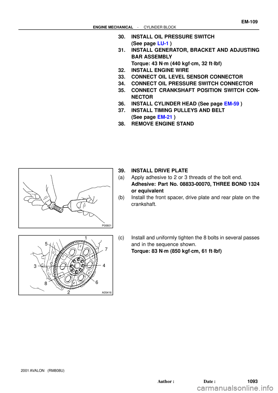
39. INSTALL DRIVE PLATE
(a) Apply adhesive to 2 or 3 threads of the bolt end.
Adhesive: Part No. 08833-00070, THREE BOND 1324
or equivalent
(b) Install the front spacer, drive plate and rear plate on the
crankshaft.
(c) Install and uniformly tighten the 8 bolts in several passes
and in the sequence shown.
Torque: 83 N´m (850 kgf´cm, 61 ft´lbf)
Page 1316 of 1897
EM0ZP-02
EM6363
SST
EM6364
Oil
Hole
EM6535
P00326
P12589
- ENGINE MECHANICALCYLINDER BLOCK
EM-99
1083 Author�: Date�:
2001 AVALON (RM808U)
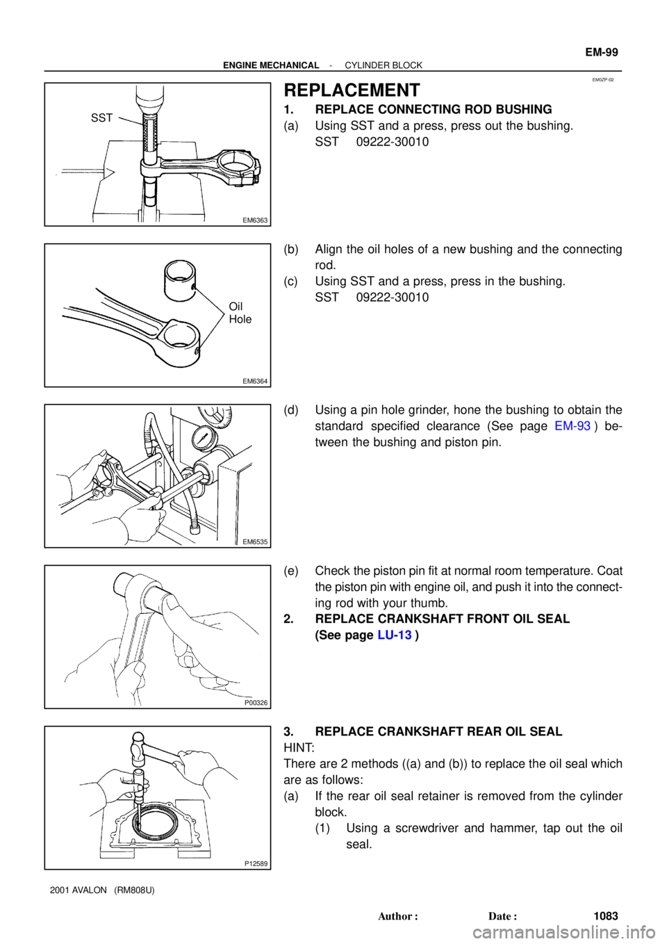
REPLACEMENT
1. REPLACE CONNECTING ROD BUSHING
(a) Using SST and a press, press out the bushing.
SST 09222-30010
(b) Align the oil holes of a new bushing and the connecting
rod.
(c) Using SST and a press, press in the bushing.
SST 09222-30010
(d) Using a pin hole grinder, hone the bushing to obtain the
standard specified clearance (See page EM-93) be-
tween the bushing and piston pin.
(e) Check the piston pin fit at normal room temperature. Coat
the piston pin with engine oil, and push it into the connect-
ing rod with your thumb.
2. REPLACE CRANKSHAFT FRONT OIL SEAL
(See page LU-13)
3. REPLACE CRANKSHAFT REAR OIL SEAL
HINT:
There are 2 methods ((a) and (b)) to replace the oil seal which
are as follows:
(a) If the rear oil seal retainer is removed from the cylinder
block.
(1) Using a screwdriver and hammer, tap out the oil
seal.