Page 1008 of 1897
- DIAGNOSTICSENGINE
DI-129
285 Author�: Date�:
2001 AVALON (RM808U)
OK
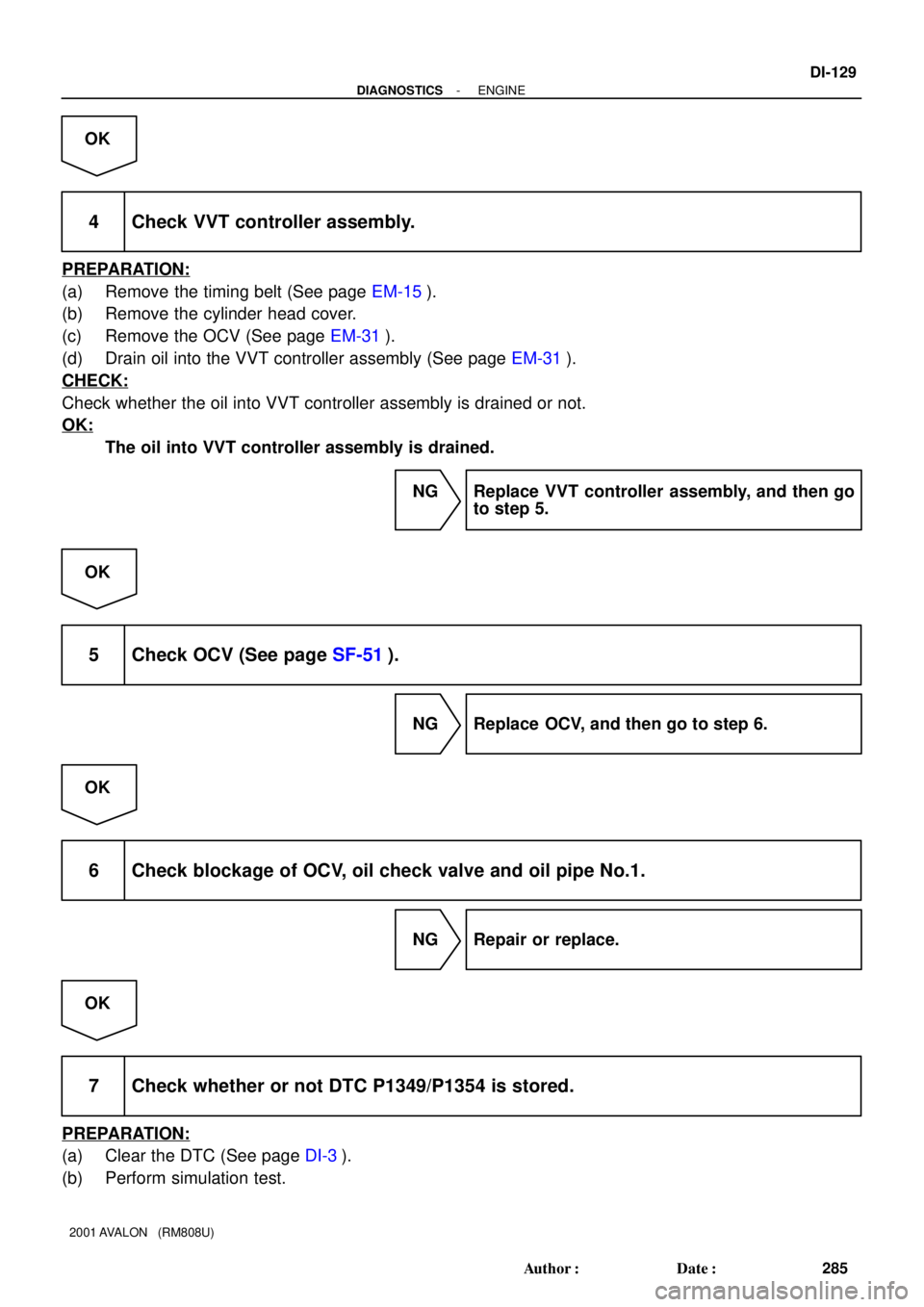
4 Check VVT controller assembly.
PREPARATION:
(a) Remove the timing belt (See page EM-15).
(b) Remove the cylinder head cover.
(c) Remove the OCV (See page EM-31).
(d) Drain oil into the VVT controller assembly (See page EM-31).
CHECK:
Check whether the oil into VVT controller assembly is drained or not.
OK:
The oil into VVT controller assembly is drained.
NG Replace VVT controller assembly, and then go
to step 5.
OK
5 Check OCV (See page SF-51).
NG Replace OCV, and then go to step 6.
OK
6 Check blockage of OCV, oil check valve and oil pipe No.1.
NG Repair or replace.
OK
7 Check whether or not DTC P1349/P1354 is stored.
PREPARATION:
(a) Clear the DTC (See page DI-3).
(b) Perform simulation test.
Page 1009 of 1897
DI-130
- DIAGNOSTICSENGINE
286 Author�: Date�:
2001 AVALON (RM808U)
CHECK:
Check whether or not DTC P1349/P1354 is stored (See page DI-3).
OK:
DTC P1349/P1354 is not stored.
OK VVT system is OK.*
*: DTCs P1349 and P1354 are also output after the foreign ob-
ject is caught in some part of the system in the engine oil and
the system returns to normal in a short time. As ECM controls
so that foreign objects are ejected, there is no problem about
VVT. There is also no problem since the oil filter should get the
foreign object in the engine oil.
NG
Replace ECM
OBD II scan tool (excluding TOYOTA hand-held tester):
1 Check valve timing (See page EM-15).
NG Repair valve timing.
OK
Page 1010 of 1897

(b)
A02397
OCV Signal Waveform
1 msec./Division5 V/
Division
GND
(A) (A) (A)
- DIAGNOSTICSENGINE
DI-131
287 Author�: Date�:
2001 AVALON (RM808U)
2 Check operation of OCV.
PRE")
A06076
OCV Connector(a)
(b)
A02397
OCV Signal Waveform
1 msec./Division5 V/
Division
GND
(A) (A) (A)
- DIAGNOSTICSENGINE
DI-131
287 Author�: Date�:
2001 AVALON (RM808U)
2 Check operation of OCV.
PREPARATION:
Start the engine.
CHECK:
(a) Check the engine speed when disconnecting the OCV
connector.
(b) Check the engine speed when applying battery positive
voltage between the terminals of the OCV.
RESULT:
ResultCheck (a)Check (b)
1Normal engine speedRough idle or engine stall
2Except 1
2 Go to step 4.
1
3 Check voltage between terminals OCV+ and OCV- of ECM connector.
Reference: INSPECTION USING OSCILLOSCOPE
Turn the ignition switch ON, check the waveform between termi-
nals OCV+ and OCV- of the ECM connector.
HINT:
�The correct waveform is as shown.
�The waveform frequency (A) is lengthened as the engine
speed becomes higher.
OK VVT system is OK.*
*: DTCs P1349 and P1354 are also output after the foreign ob-
ject is caught in some part of the system in the engine oil and
the system returns to normal in a short time. As ECM controls
so that foreign objects are ejected, there is no problem about
VVT. There is also no problem since the oil filter should get the
foreign object in the engine oil.
NG
Page 1011 of 1897
DI-132
- DIAGNOSTICSENGINE
288 Author�: Date�:
2001 AVALON (RM808U)
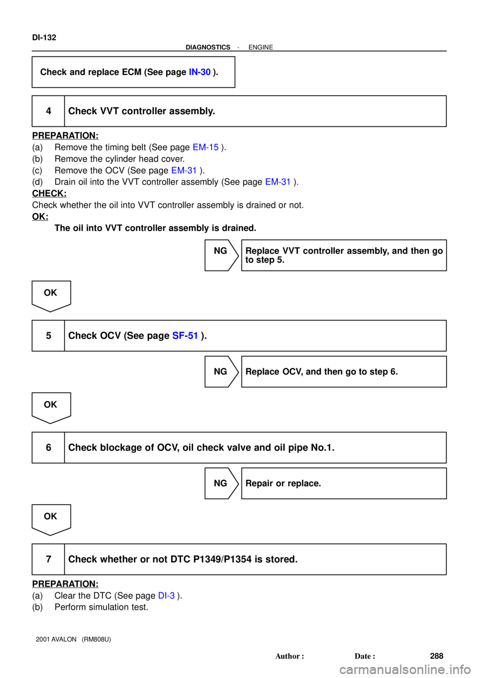
Check and replace ECM (See page IN-30).
4 Check VVT controller assembly.
PREPARATION:
(a) Remove the timing belt (See page EM-15).
(b) Remove the cylinder head cover.
(c) Remove the OCV (See page EM-31).
(d) Drain oil into the VVT controller assembly (See page EM-31).
CHECK:
Check whether the oil into VVT controller assembly is drained or not.
OK:
The oil into VVT controller assembly is drained.
NG Replace VVT controller assembly, and then go
to step 5.
OK
5 Check OCV (See page SF-51).
NG Replace OCV, and then go to step 6.
OK
6 Check blockage of OCV, oil check valve and oil pipe No.1.
NG Repair or replace.
OK
7 Check whether or not DTC P1349/P1354 is stored.
PREPARATION:
(a) Clear the DTC (See page DI-3).
(b) Perform simulation test.
Page 1012 of 1897
- DIAGNOSTICSENGINE
DI-133
289 Author�: Date�:
2001 AVALON (RM808U)
CHECK:
Check whether or not DTC P1349/P1354 is stored (See page DI-3).
OK:
DTC P1349/P1354 is not stored.
OK VVT system is OK.*
*: DTCs P1349 and P1354 are also output after the foreign ob-
ject is caught in some part of the system in the engine oil and
the system returns to normal in a short time. As ECM controls
so that foreign objects are ejected, there is no problem about
VVT. There is also no problem since the oil filter should get the
foreign object in the engine oil.
NG
Replace ECM.
Page 1017 of 1897

DTC P1656 OCV Circuit Malfunction (bank 1)
DTC P1663 OCV Circuit Malfunction (bank 2)
CIRCUIT DESCRIPTION
Refer to DTC P1349, P135")
DI-138
- DIAGNOSTICSENGINE
294 Author�: Date�:
2001 AVALON (RM808U)
DTC P1656 OCV Circuit Malfunction (bank 1)
DTC P1663 OCV Circuit Malfunction (bank 2)
CIRCUIT DESCRIPTION
Refer to DTC P1349, P1354 on page DI-127.
DTC No.DTC Detecting ConditionTrouble Area
P1656
P1663Open or short in oil control valve circuit
�Open or short in OCV circuit
�OCV
�ECM
WIRING DIAGRAM
Refer to DTC P1349, P1354 on page DI-127.
INSPECTION PROCEDURE
HINT:
�If DTC P1656 dysplayed, check left bank OCV circuit.
�If DTC P1663 dysplayed, check right bank OCV circuit.
�Read freeze frame data using TOYOTA hand-held tester or OBD II scan tool. Because freeze frame
records the engine conditions when the malfunction is detected. When troubleshooting, it is useful for
determining whether the vehicle was running or stopped, the engine was warmed up or not, the air-fuel
ratio was lean or rich, etc. at the time of the malfunction.
TOYOTA hand-held tester:
1 Check OCV circuit.
PREPARATION:
(a) Start the engine and warmed it up.
(b) Connect the TOYOTA hand-held tester and select the VVT from the ACTIVE TEST menu.
CHECK:
Check the engine speed when operate the OCV by the TOYOTA hand-held tester.
OK:
VVT system is OFF (OCV is OFF): Normal engine speed
VVT system is ON (OCV is ON): Rough idle or engine stalled
OK Check for intermittent problems
(See page DI-3).
NG
DI6TC-01
Page 1033 of 1897
Detection ItemTrouble AreaMIL*Memory
P1130
(DI-106)A/F Sensor Circuit Range/Perfor-
mance Malfunction (Bank 1 Se")
- DIAGNOSTICSENGINE
DI-17
173 Author�: Date�:
MANUFACTURER CONTROLLED
DTC No.
(See page)Detection ItemTrouble AreaMIL*Memory
P1130
(DI-106)A/F Sensor Circuit Range/Perfor-
mance Malfunction (Bank 1 Sen-
sor 1)
�Open or short in A/F sensor circuit
�A/F sensor
�Air induction system
�Fuel pressure
�Injector
�ECM
��
P1133
(DI-1 11)A/F Sensor Circuit Response
Malfunction (Bank 1 Sensor 1)
�Open or short in A/F sensor circuit
�A/F sensor
�Air induction system
�Fuel pressure
�Injector
�ECM
��
P1135
(DI-1 15)A/F Sensor Heater Circuit Mal-
function (Bank 1 Sensor 1)�Open or short in heater circuit of A/F sensor
�A/F sensor heater
�ECM
��
P1150
(DI-106)A/F Sensor Circuit Range/Perfor-
mance Malfunction (Bank 2 Sen-
sor 1)
�Same as DTC No. P1130��
P1153
(DI-1 11)A/F Sensor Circuit Response
Malfunction (Bank 2 Sensor 1)�Same as DTC No. P1133��
P1155
(DI-1 15)A/F Sensor Heater Circuit Mal-
function (Bank 2 Sensor 1)�Same as DTC No. P1135��
P1300
(DI-1 17)Igniter Circuit Malfunction (No.1)
�Ignition system
�Open or short in IGF1 or IGT1 circuit from No.1 ignition coil
with igniter to ECM
�No.1 ignition coil with igniter
�ECM
��
P1305
(DI-1 17)Igniter Circuit Malfunction (No.2)
�Ignition system
�Open or short in IGF2 or IGT2 circuit from No.2 ignition coil
with igniter to ECM
�No.2 ignition coil with igniter
�ECM
��
P1310
(DI-1 17)Igniter Circuit Malfunction (No.3)
�Ignition system
�Open or short in IGF2 or IGT3 circuit from No.3 ignition coil
with igniter to ECM
�No.3 ignition coil with igniter
�ECM
��
P1315
(DI-1 17)Igniter Circuit Malfunction (No.4)
�Ignition system
�Open or short in IGF1 or IGT4 circuit from No.4 ignition coil
with igniter to ECM
�No.4 ignition coil with igniter
�ECM
��
P1320
(DI-1 17)Igniter Circuit Malfunction (No.5)
�Ignition system
�Open or short in IGF2 or IGT5 circuit from No.5 ignition coil
with igniter to ECM
�No.5 ignition coil with igniter
�ECM
��
P1325
(DI-1 17)Igniter Circuit Malfunction (No.6)
�Ignition system
�Open or short in IGF1 or IGT6 circuit from No.6 ignition coil
with igniter to ECM
�No.6 ignition coil with igniter
�ECM
��
Page 1036 of 1897
DI07C-09
A11424
Knock Sensor 1 DLC1
IAC Valve VSV for EVAP
Engine Coolant
Temp. Sensor
Injector
Crankshaft Position
Sensor
A/F Sensor
(Bank 2 Sensor 1)Park/Neutral Position SwitchDLC3 ECM
Heated Oxygen Sensor
(Bank 1 Sensor 2)
VVT Sensor
(Bank 2)VVT Sensor (Bank 1)
OCV (Bank 2)OCV (Bank 1)
Canister
Vapor Pressure Sensor A/F Sensor
(Bank 1 Sensor 1)
VSV for Pressure Switching Valve VSV for CCV
Ignition Coil
with lgniter
Mass Air Flow Meter
Throttle Position Sensor
Combination Meter
VSV for
No.1 ACIS
VSV for
No.2 ACIS
Knock Sensor 2
- DIAGNOSTICSENGINE
DI-19
175 Author�: Date�:
2001 AVALON (RM808U)
PARTS LOCATION


Park/Neutral Position SwitchDLC3 ECM
Heated Oxyg")