Page 578 of 1897
CO02W-03
B09039
Radiator
No.1 ECT Switch
No.2 Cooling Fan Connector
Upper Radiator
Support
Upper Radiator
HoseNo.1 Cooling Fan Connector
No.1 ECT Switch Wire Connector
Radiator Assembly
Lower Radiator
Support� O-Ring
A/T Oil Cooler Hose
No.3 Engine
Room Relay Block No.1 Cooling Fan
� Non-reusable part � O-Ring
Drain Plug
Lower Radiator
Hose
No.2 Cooling Fan
Battery
Insulator
Battery
Battery
Tray Hold-Down
Clamp
Engine Under Cover
- COOLINGRADIATOR
CO-15
1208 Author�: Date�:
2001 AVALON (RM808U)
COMPONENTS
Page 579 of 1897
B09036
� O-Ring
� Non-reusable partUpper Tank
Cushion
Core
Oil Cooler
Lower TankInlet Pipe
Plate WasherNut
� O-Ring � O-Ring
CO-16
- COOLINGRADIATOR
1209 Author�: Date�:
2001 AVALON (RM808U)
Page 580 of 1897

CO02Y-03
CO1205
Dimension ºBºPart ºAº
Stopper Bolt SST
Claw
Overhaul Handle
B09048
Tank
SST
Lock Plate
Stopper Bolt
B09042
Ta p
B09043
CO-18
- COOLINGRADIATOR
1211 Author�: Date�:
2001 AVALON (RM808U)
DISASSEMBLY
1. REMOVE CUSHION FROM RADIATOR
2. ASSEMBLE SST
SST 09230-01010
(a) Install the claw to the overhaul handle, inserting it in the
hole in part ºAº as shown in the diagram.
(b) While gripping the handle, adjust the stopper bolt so that
dimension ºBº shown in the diagram is 0.2 - 0.5 mm
(0.008 - 0.020 in.).
NOTICE:
If this adjustment is not done, the claw may be damaged.
3. UNCAULK LOCK PLATES
Using SST to release the caulking, squeeze the handle until
stopped by the stopper bolt.
SST 09230-01010
4. REMOVE TANKS AND O-RINGS
(a) Lightly tap the bracket of the radiator (or radiator hose in-
let or outlet) with a soft-faced hammer and remove the
tank.
(b) Remove the O-ring.
5. REMOVE OIL COOLER FROM LOWER TANK
(a) Remove the pipe.
(b) Remove the nuts and plate washers.
(c) Remove the oil cooler and O-rings.
Page 584 of 1897
(2)
(3)(4) (5) (6)
CO1267
Lock Plate
Lock Plate
Core
CO0317
O-Ring� Normal
X Twisted
X Twisted
- COOLINGRADIATOR
CO-19
1212 Author�: Date�:
2001 AVALON (RM808U)
REASSEMBLY
1. INST")
CO02Z-03
S04435
(1)(2)
(3)(4) (5) (6)
CO1267
Lock Plate
Lock Plate
Core
CO0317
O-Ring� Normal
X Twisted
X Twisted
- COOLINGRADIATOR
CO-19
1212 Author�: Date�:
2001 AVALON (RM808U)
REASSEMBLY
1. INSTALL OIL COOLER TO LOWER TANK
(a) Clean the O-ring contact surface of the lower tank and oil
cooler.
(b) Install a new O-rings (1) to the oil cooler (2).
(c) Install the oil cooler with the O-rings to the lower tank (3).
(d) Install the plate washers (4), and nuts (5). Torque the
nuts.
Torque: 8.3 N´m (85 kgf´cm, 74 in.´lbf)
(e) Install the pipe (6).
Torque: 14.7 N´m (150 kgf´cm, 11 ft´lbf)
2. INSPECT LOCK PLATE
Inspect the lock plate for damage.
HINT:
�If the sides of the lock plate groove are deformed, reas-
sembly of the tank will be impossible.
�Therefore, first correct any deformation with pliers or simi-
lar object. Water leakage will result if the bottom of the
lock plate groove is damaged or dented, Therefore, repair
or replace if necessary.
NOTICE:
The radiator can only be recaulked 2 times. After the 2nd
time, the radiator core must be replaced.
3. INSTALL NEW O-RINGS AND TANKS
(a) After checking that there are no foreign objects in the lock
plate groove, install the new O-ring without twisting it.
HINT:
When cleaning the lock plate groove, lightly rub it with sand pa-
per without scratching it.
Page 586 of 1897
B09041
B09046
H
- COOLINGRADIATOR
CO-21
1214 Author�: Date�:
2001 AVALON (RM808U)
�The points shown in the rib sides and oil cooler near here
cannot be staked with SST. Use pliers or similar object
and be careful not to damage the core plates.
(b) Check the lock plate height (H) after completing the caulk-
ing.
Plate height (H): 7.4 - 7.8 mm (0.2959 - 0.3119 in.)
If not within the specified height, adjust the stopper bolt of the
handle again and caulk again.
6. INSTALL CUSHION
Page 587 of 1897

REMOVAL
HINT:
At the time of installation, please refer to the following items.
�Start the engine, and check for coo")
CO0WT-01
B09040
- COOLINGRADIATOR
CO-17
1210 Author�: Date�:
2001 AVALON (RM808U)
REMOVAL
HINT:
At the time of installation, please refer to the following items.
�Start the engine, and check for coolant and A/T fluid
leaks.
�Check the A/T fluid level (See page DI-160).
1. REMOVE BATTERY AND BATTERY TRAY
2. REMOVE ENGINE UNDER COVER
3. DRAIN ENGINE COOLANT
4. DISCONNECT NO.3 ENGINE ROOM RELAY BLOCK
FROM RADIATOR
5. DISCONNECT NO.1 COOLING FAN CONNECTOR
6. DISCONNECT WIRE CLAMPS FROM NO.1 FAN
SHROUD
7. DISCONNECT NO.2 COOLING FAN CONNECTOR
8. DISCONNECT NO.1 ECT SWITCH WIRE CONNECTOR
9. DISCONNECT WIRE CLAMPS FROM NO.2 FAN
SHROUD
10. DISCONNECT UPPER RADIATOR HOSE FROM RA-
DIATOR
11. DISCONNECT LOWER RADIATOR HOSE FROM RA-
DIATOR
12. DISCONNECT A/T OIL COOLER HOSES FROM RA-
DIATOR
13. REMOVE RADIATOR AND COOLING FANS AS-
SEMBLY
(a) Remove the 2 bolts and 2 upper supports.
Torque: 12.8 N´m (130 kgf´cm, 9 ft´lbf)
(b) Lift out the radiator, and remove the radiator and cooling
fans assembly.
(c) Remove the 2 lower supports.
14. REMOVE NO.1 ECT SWITCH
15. REMOVE NO.1 COOLING FAN FROM RADIATOR
Remove the 2 bolts and cooling fan.
Torque: 5.0 N´m (50 kgf´cm, 44 in.´lbf)
16. REMOVE NO.2 COOLING FAN FROM RADIATOR
Remove the 2 bolts and cooling fan.
Torque: 5.0 N´m (50 kgf´cm, 44 in.´lbf)
Page 596 of 1897
CO02P-03
P12942
CO-8
- COOLINGWATER PUMP
1201 Author�: Date�:
2001 AVALON (RM808U)
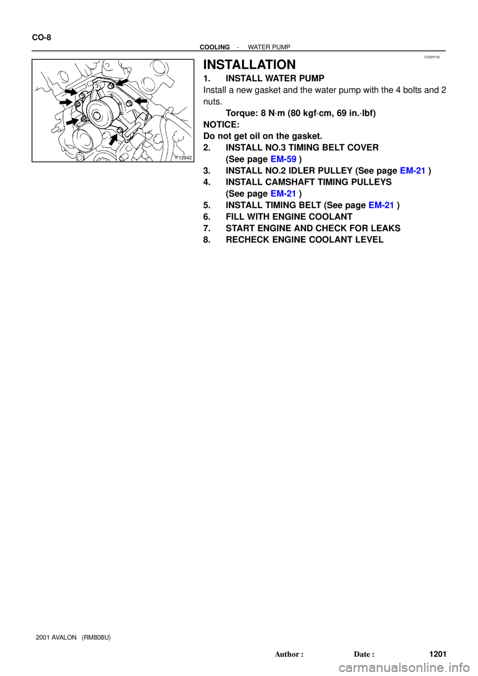
INSTALLATION
1. INSTALL WATER PUMP
Install a new gasket and the water pump with the 4 bolts and 2
nuts.
Torque: 8 N´m (80 kgf´cm, 69 in.´lbf)
NOTICE:
Do not get oil on the gasket.
2. INSTALL NO.3 TIMING BELT COVER
(See page EM-59)
3. INSTALL NO.2 IDLER PULLEY (See page EM-21)
4. INSTALL CAMSHAFT TIMING PULLEYS
(See page EM-21)
5. INSTALL TIMING BELT (See page EM-21)
6. FILL WITH ENGINE COOLANT
7. START ENGINE AND CHECK FOR LEAKS
8. RECHECK ENGINE COOLANT LEVEL
Page 612 of 1897
DI-225
381 Author�: Date�:
2001")
BR3583
BR3582F00010
RotorSpeed Sensor
Magnet
To ECU
+V
-VHigh Speed
Low Speed
CoilNS
- DIAGNOSTICSANTI-LOCK BRAKE SYSTEM WITH ELECTRONIC
BRAKE FORCE DISTRIBUTION (EBD)DI-225
381 Author�: Date�:
2001 AVALON (RM808U)
DTC 31 - 36, 38, 39 Speed Sensor Circuit
CIRCUIT DESCRIPTION
The speed sensor detects wheel speed and sends the ap-
propriate signals to the ECU. These signals are used to control
the ABS system. Each of the front and rear rotors has 48 serra-
tions.
When the rotors rotate, a magnetic field emitted by a permanent
magnet in the speed sensor generates an AC voltage. Since
the frequency of this AC voltage changes in direct proportion to
the speed of the rotor, the frequency is used by the ECU to de-
tect the speed of each wheel.
DTC No.DTC Detecting ConditionTrouble Area
31, 32, 33, 34
When any of the following 1. through 3. is detected:
1. Vehicle speed is more than 40 km/h (25 mph), and
pulses are not input for 0.01 sec.
2. After the initial start or restart and when the vehicle
speed has reached 12 km/h (7 mph), the wheel speed of
0 km/h (0 mph) is detected.
3. After the initial start or restart and when the vehicle
speed has reached 18 km/h (11 mph), the front wheel
speed of 0 km/h (0 mph) is detected.
�Right front, left front, right rear, left rear speed sensor
�Each speed sensor circuit
�Sensor installation
35, 36, 38, 39Detecting abnormality in the resistance value of each speed
sensor.�Right front, left front, right rear, left rear speed sensor
�Each speed sensor circuit
HINT:
�DTC No. 31 and 35 are for the right front speed sensor.
�DTC No. 32 and 36 are for the left front speed sensor.
�DTC No. 33 and 38 are for the right rear speed sensor.
�DTC No. 34 and 39 are for the left rear speed sensor.
DI6NF-02