Page 345 of 1897
BO0XJ-04
H12099: Specified torqueN´m (kgf´cm, ft´lbf)
Oil Cooler
11 (115, 8)
5.4 (55, 48 in.´lbf)
11 (115, 8)
Front Bumper
Upper Reinforcement
RH Side Support
RH No. 2 Extension
Insert
LH Side Support
13 (130, 9)
Front Bumper Reinforcement
LH No. 2 Extension
Insert
13 (130, 9)
Front Bumper Energy Absorber
5.4 (55, 48 in.´lbf)
5.4 (55, 48 in.´lbf)
Front Bumper Cover
w/o Fog light:
RH Hole Cover
w/ Fog light:
RH Fog Light Assembly
8.3 (85, 74 in.´lbf)
w/ Fog light:
LH Fog Light Assembly
w/o Fog light:
LH Hole Cover
11 (115, 8)
BO-4
- BODYFRONT BUMPER
1789 Author�: Date�:
2001 AVALON (RM808U)
FRONT BUMPER
COMPONENTS
Page 376 of 1897

BO0XM-03
H12101
150 mm (5.91 in.)
- BODYHOOD SUPPORT
BO-7
1792 Author�: Date�:
2001 AVALON (RM808U)
HOOD SUPPORT
REPLACEMENT
1. REMOVE SUPPORT FROM HOOD
Remove the bolt and support from the hood.
HINT:
While supporting the hood by hand, remove the support.
2. REMOVE SUPPORT FROM BODY
Remove the bolt and support.
3. IF NECESSARY, REPLACE HOOD SUPPORT
NOTICE:
Handling the hood support
�Do not disassemble the support because the cylinder
is filled with pressurized gas.
�If the support is to be replaced, drill a 2.0 - 3.0 mm
(0.079 - 0.118 in.) hole in the area shown in the il-
lustration to completely discharge the high-pressure
gas before disposing of it.
�When drilling, chips may fly out so work carefully.
�The gas is colorless, odorless and non-toxic.
�When working, handle the support carefully. Never
score or scratch the exposed part of the piston rod,
and allow any paint or oil to get on it.
�Do not turn the piston rod and cylinder with the sup-
port fully extended.
4. INSTALL HOOD SUPPORT
(a) Install the bolt and hood support to the body.
Torque: 17 N´m (175 kgf´cm, 13 ft´lbf)
(b) Install the bolts and hood support to the hood.
Torque: 17 N´m (175 kgf´cm, 13 ft´lbf)
Page 519 of 1897

BR0L1-04
F06984
F06985
BR-26
- BRAKEFRONT BRAKE PAD
1425 Author�: Date�:
2001 AVALON (RM808U)
REPLACEMENT
1. REMOVE FRONT WHEEL
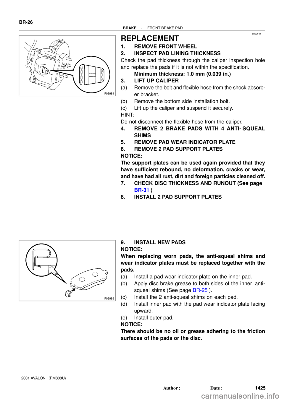
2. INSPECT PAD LINING THICKNESS
Check the pad thickness through the caliper inspection hole
and replace the pads if it is not within the specification.
Minimum thickness: 1.0 mm (0.039 in.)
3. LIFT UP CALIPER
(a) Remove the bolt and flexible hose from the shock absorb-
er bracket.
(b) Remove the bottom side installation bolt.
(c) Lift up the caliper and suspend it securely.
HINT:
Do not disconnect the flexible hose from the caliper.
4. REMOVE 2 BRAKE PADS WITH 4 ANTI- SQUEAL
SHIMS
5. REMOVE PAD WEAR INDICATOR PLATE
6. REMOVE 2 PAD SUPPORT PLATES
NOTICE:
The support plates can be used again provided that they
have sufficient rebound, no deformation, cracks or wear,
and have had all rust, dirt and foreign particles cleaned off.
7. CHECK DISC THICKNESS AND RUNOUT (See page
BR-31)
8. INSTALL 2 PAD SUPPORT PLATES
9. INSTALL NEW PADS
NOTICE:
When replacing worn pads, the anti-squeal shims and
wear indicator plates must be replaced together with the
pads.
(a) Install a pad wear indicator plate on the inner pad.
(b) Apply disc brake grease to both sides of the inner anti-
squeal shims (See page BR-25).
(c) Install the 2 anti-squeal shims on each pad.
(d) Install inner pad with the pad wear indicator plate facing
upward.
(e) Install outer pad.
NOTICE:
There should be no oil or grease adhering to the friction
surfaces of the pads or the disc.
Page 540 of 1897

BR0LB-02
F09725
BR-38
- BRAKEREAR BRAKE CALIPER
1437 Author�: Date�:
2001 AVALON (RM808U)
REMOVAL
1. REMOVE REAR WHEEL
Remove the wheel and temporarily fasten the disc with hub
nuts.
Torque: 103 N´m (1,050 kgf´cm, 76 ft´lbf)
2. DISCONNECT FLEXIBLE HOSE
(a) Remove the union bolt and 2 gaskets from the caliper,
then disconnect the flexible hose from the caliper.
Torque: 29 N´m (300 kgf´cm, 22 ft´lbf)
HINT:
At the time of installation, insert the flexible hose lock securely
in the lock hole in the caliper.
(b) Use a container to catch the brake fluid as it drains out.
3. REMOVE CALIPER
(a) Remove the 2 installation bolts.
Torque: 34 N´m (350 kgf´cm, 25 ft´lbf)
NOTICE:
At the time of installation, insert the sliding pin with sliding
bushing into the bottom side.
(b) Remove the caliper from the torque plate.
4. REMOVE 2 BRAKE PADS WITH ANTI- SQUEAL
SHIMS
5. REMOVE 4 PAD SUPPORT PLATES
NOTICE:
There should be no oil or grease adhering to the friction
surfaces of the pads or disc.
Page 542 of 1897

BR0L9-03
F09722
F09723
R10387
- BRAKEREAR BRAKE PAD
BR-35
1434 Author�: Date�:
2001 AVALON (RM808U)
REPLACEMENT
1. REMOVE REAR WHEEL
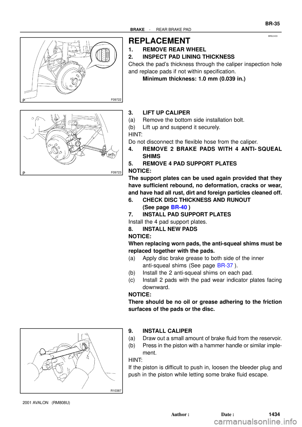
2. INSPECT PAD LINING THICKNESS
Check the pad's thickness through the caliper inspection hole
and replace pads if not within specification.
Minimum thickness: 1.0 mm (0.039 in.)
3. LIFT UP CALIPER
(a) Remove the bottom side installation bolt.
(b) Lift up and suspend it securely.
HINT:
Do not disconnect the flexible hose from the caliper.
4. REMOVE 2 BRAKE PADS WITH 4 ANTI- SQUEAL
SHIMS
5. REMOVE 4 PAD SUPPORT PLATES
NOTICE:
The support plates can be used again provided that they
have sufficient rebound, no deformation, cracks or wear,
and have had all rust, dirt and foreign particles cleaned off.
6. CHECK DISC THICKNESS AND RUNOUT
(See page BR-40)
7. INSTALL PAD SUPPORT PLATES
Install the 4 pad support plates.
8. INSTALL NEW PADS
NOTICE:
When replacing worn pads, the anti-squeal shims must be
replaced together with the pads.
(a) Apply disc brake grease to both side of the inner
anti-squeal shims (See page BR-37).
(b) Install the 2 anti-squeal shims on each pad.
(c) Install 2 pads with the pad wear indicator plates facing
downward.
NOTICE:
There should be no oil or grease adhering to the friction
surfaces of the pads or the disc.
9. INSTALL CALIPER
(a) Draw out a small amount of brake fluid from the reservoir.
(b) Press in the piston with a hammer handle or similar imple-
ment.
HINT:
If the piston is difficult to push in, loosen the bleeder plug and
push in the piston while letting some brake fluid escape.
Page 547 of 1897

BR0KG-05
BR-2
- BRAKETROUBLESHOOTING
1401 Author�: Date�:
2001 AVALON (RM808U)
TROUBLESHOOTING
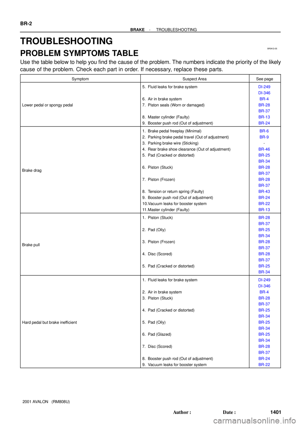
PROBLEM SYMPTOMS TABLE
Use the table below to help you find the cause of the problem. The numbers indicate the priority of the likely
cause of the problem. Check each part in order. If necessary, replace these parts.
SymptomSuspect AreaSee page
Lower pedal or spongy pedal
5. Fluid leaks for brake system
6. Air in brake system
7. Piston seals (Worn or damaged)
8. Master cylinder (Faulty)
9. Booster push rod (Out of adjustment)DI-249
DI-346
BR-4
BR-28
BR-37
BR-13
BR-24
Brake drag
1. Brake pedal freeplay (Minimal)
2. Parking brake pedal travel (Out of adjustment)
3. Parking brake wire (Sticking)
4. Rear brake shoe clearance (Out of adjustment)
5. Pad (Cracked or distorted)
6. Piston (Stuck)
7. Piston (Frozen)
8. Tension or return spring (Faulty)
9. Booster push rod (Out of adjustment)
10.Vacuum leaks for booster system
11. Master cylinder (Faulty)BR-6
BR-9
-
BR-46
BR-25
BR-34
BR-28
BR-37
BR-28
BR-37
BR-43
BR-24
BR-22
BR-13
Brake pull
1. Piston (Stuck)
2. Pad (Oily)
3. Piston (Frozen)
4. Disc (Scored)
5. Pad (Cracked or distorted)BR-28
BR-37
BR-25
BR-34
BR-28
BR-37
BR-28
BR-37
BR-25
BR-34
Hard pedal but brake inefficient
1. Fluid leaks for brake system
2. Air in brake system
3. Piston (Stuck)
4. Pad (Cracked or distorted)
5. Pad (Oily)
6. Pad (Glazed)
7. Disc (Scored)
8. Booster push rod (Out of adjustment)
9. Vacuum leaks for booster systemDI-249
DI-346
BR-4
BR-28
BR-37
BR-25
BR-34
BR-25
BR-34
BR-25
BR-34
BR-28
BR-37
BR-24
BR-22
Page 556 of 1897

CH03Y-01
CH0784
Ohmmeter
Continuity
B02105
Ohmmeter
No Continuity
CH0192
P00484
OhmmeterContinuity
P00482
OhmmeterContinuity
- CHARGINGGENERATOR
CH-9
1282 Author�: Date�:
2001 AVALON (RM808U)
INSPECTION
1. INSPECT ROTOR
(a) Inspect the rotor for open circuit.
Using an ohmmeter, check that there is continuity be-
tween the slip rings.
Standard resistance: 2.1 - 2.5 W at 20°C (68°F)
If there is no continuity, replace the rotor.
(b) Inspect the rotor for ground.
Using an ohmmeter, check that there is no continuity be-
tween the slip ring and rotor.
If there is continuity, replace the rotor.
(c) Check that the slip rings are not rough or scored.
If rough or scored, replace the rotor.
(d) Using vernier calipers, measure the slip ring diameter.
Standard diameter: 14.2 - 14.4 mm (0.559-0.567 in.)
Minimum diameter: 12.8 mm (0.504 in.)
If the diameter is less than minimum, replace the rotor.
2. INSPECT STATOR (DRIVE END FLAME)
(a) Inspect the stator for open circuit.
Using an ohmmeter, check that there is continuity be-
tween the coil leads.
If there is no continuity, replace the drive end frame assembly.
(b) Inspect the stator for ground.
Using an ohmmeter, check that there is no continuity be-
tween the coil lead and drive end frame.
If there is continuity, replace the drive end frame assembly.
Page 568 of 1897
CO02K-03
- COOLINGCOOLANT
CO-1
1194 Author�: Date�:
2001 AVALON (RM808U)
COOLANT
INSPECTION
1. CHECK ENGINE COOLANT LEVEL AT RADIATOR RESERVOIR
The engine coolant level should be between the ºLOWº and ºFULLº lines, when the engine is cold.
If low, check for leaks and add ''Toyota Long Life Coolantº or Equivalent up to the ºFULLº line.
2. CHECK ENGINE COOLANT QUALITY
(a) Remove the radiator cap from the water outlet.
CAUTION:
To avoid the danger of being burned, do not remove the radiator cap while the engine and radiator
are still hot, as fluid and steam can be blown out under pressure.
(b) There should not be any excessive deposits of rust or scale around the radiator cap or water outlet
filler hole, and the coolant should be free from oil.
If excessively dirty, clean the coolant passages and replace the coolant.
(c) Reinstall the radiator cap.