Page 148 of 1897

D01059
A
B
D01021
B
B
A
Z19257
30
(1.18)
BAmm (in.)
Q05728
Connector AX-10
- AUTOMATIC TRANSAXLEVALVE BODY ASSEMBLY
1300 Author�: Date�:
2001 AVALON (RM808U)
19. INSTALL CONNECTOR CLAMP AND PIPE RETAINER
Install the connector clamp and pipe retainer with the 2 bolts.
Torque: 6.6 N´m (67 kgf´cm, 58 in.´lbf)
Bolt length:
Bolt A: 48 mm (1.890 in.)
Bolt B: 39 mm (1.535 in.)
20. INSTALL MANUAL VALVE BODY
(a) Aligning the valve body with the pin on the manual shaft
lever.
(b) Lower the manual valve body into place.
(c) Temporarily the 5 bolts first. Then, tighten them with a
torque wrench.
Torque: 11 N´m (110 kgf´cm, 8 ft´lbf)
Bolt length:
Bolt A: 22 mm (0.866 in.)
Bolt B: 37 mm (1.457 in.)
21. INSTALL DETENT SPRING AND OIL PIPE
(a) Place the detent springs on the manual valve body and
temporarily install the 2 bolts first. Then, tighten them with
a torque wrench.
Torque: 11 N´m (110 kgf´cm, 8 ft´lbf)
Bolt length:
Bolt A: 14 mm (0.551 in.)
Bolt B: 37 mm (1.457 in.)
(b) Check that the manual valve lever is touching the center
of the detent spring tip roller.
(c) Using a plastic hammer, install the pipe into the position.
NOTICE:
Be careful not to bend or damage the pipe.
(d) Install the bolt.
Torque: 10 N´m (100 kgf´cm, 7 ft´lbf)
22. CONNECT 3 SOLENOID CONNECTORS
23. INSTALL OIL PIPE
Using a plastic hammer, install the pipes into the positions.
NOTICE:
Be careful not to bend or damage the pipes.
Page 149 of 1897
Z19256
BA
B A
AT3741
AT3785
- AUTOMATIC TRANSAXLEVALVE BODY ASSEMBLY
AX-1 1
1301 Author�: Date�:
2001 AVALON (RM808U)
24. INSTALL OIL STRAINER AND APPLY PIPE BRACKET
Install the oil strainer and apply pipe bracket with the 6 bolts.
Torque:
Bolt A: 10 N´m (100 kgf´cm, 7 ft´lbf)
Bolt B: 11 N´m (110 kgf´cm, 8 ft´lbf)
Bolt length:
Bolt A: 22 mm (0.866 in.)
Bolt B: 53 mm (2.087 in.)
25. INSTALL MAGNET IN PLACE
Install the 3 magnets in the indentations of the oil pan, as shown
in the illustration.
NOTICE:
Make sure that the magnet does not interfere with the oil
pipes.
26. INSTALL OIL PAN AND GASKET
(a) Install the oil pan and a new gasket.
(b) Install the 17 bolts.
Torque: 7.8 N´m (80 kgf´cm, 69 in.´lbf)
27. INSTALL DRAIN PLUG
Install a new gasket and drain plug.
Torque: 49 N´m (500 kgf´cm, 36 ft´lbf)
28. FILL ATF AND CHECK FLUID LEVEL
(See page DI-160)
Page 175 of 1897

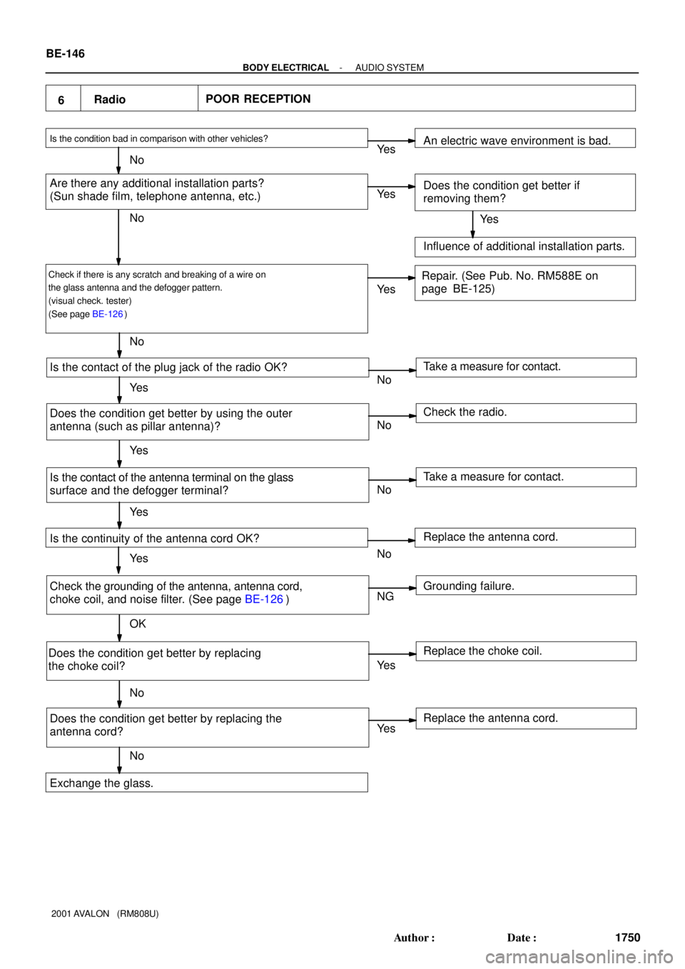
6RadioPOOR RECEPTION
Is the condition bad in comparison with other vehicles?
Are there any additional installation parts?
(Sun shade film, telephone antenna, etc.)
Check if there is any scratch and breaking of a wire on
the glass antenna and the defogger pattern.
(visual check. tester)
(See page BE-126)
Is the contact of the plug jack of the radio OK?
Does the condition get better by using the outer
antenna (such as pillar antenna)?
Is the contact of the antenna terminal on the glass
surface and the defogger terminal?
Is the continuity of the antenna cord OK?
Check the grounding of the antenna, antenna cord,
choke coil, and noise filter. (See page BE-126)
Does the condition get better by replacing
the choke coil?
Does the condition get better by replacing the
antenna cord?Take a measure for contact. An electric wave environment is bad.
Does the condition get better if
removing them?
Influence of additional installation parts.
Repair. (See Pub. No. RM588E on
page BE-125)
Check the radio.
Take a measure for contact.
Grounding failure. Replace the antenna cord.
Replace the choke coil.
Replace the antenna cord. Ye s
No
Exchange the glass.Ye s
Ye s
Ye s
Ye s
Ye s
Ye s
Ye s
Ye s No
No
No
NoNo
No
No
No
NG
OK
Ye s BE-146
- BODY ELECTRICALAUDIO SYSTEM
1750 Author�: Date�:
2001 AVALON (RM808U)
Page 187 of 1897

26 Noise NOISE OCCURS
No
Ye s
NG
OK Does the noise occur only in the radio?
Does the noise occur in a particular place?
Is there any additional installation part
around the glass imprinted antenna?
(Sun shade film, telephone antenna etc.)
Does the noise occur even pulling out the
antenna cord from the radio?
Does the noise occur even after pulling out the
antenna terminal on the glass surface?
Isn't there any adhesive (Butyl rubber)
stuck on the bases of the antenna
terminal, defogger terminal and bus bar?
Check the grounding of the antenna,
antenna cord, coke coil, and noise filter.
(See page BE-126) Does the noise occur even after pulling out
the defogger terminal?
Does the condition get better by replacing
the antenna cord.
Noise rediates directly to the antenna from the
generation source. Does the condition get better by replacing
the choke coil?
Replace the antenna cord. Replace the choke coil. Interfering noise from the defogger line
and choke coil.
Grounding failure. Failure of glass installation.
Must plane the butyl rubber. Noise mixing into the antenna cable. Check the radio. Influence of the film or the noise radiation
of the additional installation part. Does the noise stop by removing it? An electric environment.Refer to No.27. (It occurs in the cassette and CD.)
Ye s
Ye s
Ye s
Ye s
Ye s
Ye s
Ye s
Ye s No
No
No
No
No
No
No
No
BE-158
- BODY ELECTRICALAUDIO SYSTEM
1762 Author�: Date�:
2001 AVALON (RM808U)
Page 196 of 1897
I12543
E2 *2
E7 *2
C4
C7 ECU
ODO/TRIP
MODE
RESET/AD
SELECT
ON/OFF
Speed control
Unit
Open door indicator
SRS warning
SRS cut off indicator
(Passenger)
Discharge warning
Washer level warning
Low oil pressure warning
Passenger seat belt warning
VSC warning
CRUISE main indicator
ABS warning
VSC cut off warning
TRAC warning
Brake warning
Rear light indicator
Mulfunction indicator
Driver seat belt warning *1: Hi-Grade
*2: Lo-Grade
F4
F2 F7 G14 G4 F9 G7 F5 F3 F10 G10 F6F1 G8 G6 G2
G12 C11
*1
G13G5G3
G11 C18 BE-46
- BODY ELECTRICALCOMBINATION METER
1650 Author�: Date�:
2001 AVALON (RM808U)
Page 197 of 1897

C
No.Wire Connector Side
1
2
3
4
6
7
8
9
10
11
12
13
14
15
16ECU-IG No. 2 Fuse
Injector *
1
F (Panel) Fuse
Outside temperature sensor
ECM *
1
ABS ECU
Fuel sender gauge
Fuel sender gauge
Light control volume
RAD No. 1 Fuse Ground
ECU-ACC Fuse
-
Engine coolant temperature sendoer gauge
EFI
Heater control ECU *
117
18
19
20
21Speed control unit
Fuel sender gauge
-
Sender ground
Ground 22Starter Relay
D1
2
3
4
6
7
8
9
10
11
12
13
14
15
16-
Combination meter
-
-
-
- 17
18 -Low oil pressure warning switch *
2
Compressor lock sensor *2
A/C magnet switch
Evaporator temperature sensor *
2
A/C switch *2
A/C indicator *2
-
*1: Hi GradeECM
*2: Lo Grade 5
5Combination meter
Combination meter
Combination meter
Combination meter
Combination meter Combination meter
Combination meter
Combination meter
Combination meter
Combination meter
Combination meter
E
No.Wire Connector Side
1
2
3
4
6
7
8
9
10
11
12
13
14
15
16
17
18
19
205 1
2Compass sensor *1
Compass sensor *1
Compass sensor *1
-
-
-
-
-
-
-
-
-
- Compass sensor *
1
7
Compass sensor *1
- BODY ELECTRICALCOMBINATION METER
BE-47
1651 Author�: Date�:
2001 AVALON (RM808U)
Page 198 of 1897
No.Wire Connector Side
1
2
3
4
6
7
8
9
10
14
15
16Washer fluid level warning switch
Body ECU
Brake fluid level warning switch
GAUGE Fuse
Lo oil pressure warning switch
ECM
-
TRAC
VSC ECU
Light failure Sensor
-
-
G1
2
3
4
6
7
8
9
10
11
12
13-
Driver's door courtesy switch
DOME Fuse
Cruise ECU
Airbag ECU
ABS&BA&DRAC&VSC ECU
-
Body ECU
Generator L terminal Ignition switch 5 ABS ECU
5 AIR BAG WRN Fuse F
-
- BE-48
- BODY ELECTRICALCOMBINATION METER
1652 Author�: Date�:
2001 AVALON (RM808U)
Page 207 of 1897

I13321
A
DC
B
I13324
Fuel Receiver Gauge
Battery Ignition
Switch
Z15787
Battery Ignition Switch
Fuel Receiver
Gauge
Wire Harness Side
Test
Bulb
(3.4 W)
I13319
A
DC
B
I13325
F
1/2
E 32
- BODY ELECTRICALCOMBINATION METER
BE-57
1661 Author�: Date�:
2001 AVALON (RM808U)
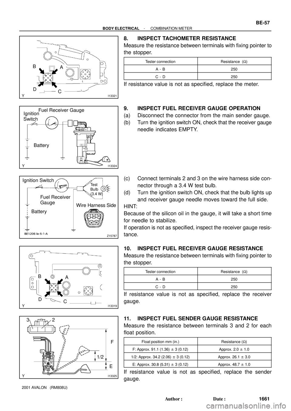
8. INSPECT TACHOMETER RESISTANCE
Measure the resistance between terminals with fixing pointer to
the stopper.
Tester connectionResistance (W)
A - B250
C - D250
If resistance value is not as specified, replace the meter.
9. INSPECT FUEL RECEIVER GAUGE OPERATION
(a) Disconnect the connector from the main sender gauge.
(b) Turn the ignition switch ON, check that the receiver gauge
needle indicates EMPTY.
(c) Connect terminals 2 and 3 on the wire harness side con-
nector through a 3.4 W test bulb.
(d) Turn the ignition switch ON, check that the bulb lights up
and receiver gauge needle moves toward the full side.
HINT:
Because of the silicon oil in the gauge, it will take a short time
for needle to stabilize.
If operation is not as specified, inspect the receiver gauge resis-
tance.
10. INSPECT FUEL RECEIVER GAUGE RESISTANCE
Measure the resistance between terminals with fixing pointer to
the stopper.
Tester connectionResistance (W)
A - B250
C - D250
If resistance value is not as specified, replace the receiver
gauge.
11. INSPECT FUEL SENDER GAUGE RESISTANCE
Measure the resistance between terminals 3 and 2 for each
float position.
Float position mm (in.)Resistance (W)
F: Approx. 91.1 (1.36) ± 3 (0.12)Approx. 2.0 ± 1.0
1/2: Approx. 34.2 (2.06) ± 3 (0.12)Approx. 26.1 ± 3.0
E: Approx. 30.8 (5.31) ± 3 (0.12)Approx. 48.7 ± 1.0
If resistance value is not as specified, replace the sender
gauge.