Page 1064 of 1897
DI1AN-06
I12540
Engine Room Junction Block
� EFI Fuse
Instrument Panel Junction Block
� IGN FuseECMIgnition Switch Assembly
� Transponder Key Amplifier
� Transponder Key Coil
� Key Unlock Warning Switch
Security Indicator
DI-602
- DIAGNOSTICSENGINE IMMOBILISER SYSTEM
758 Author�: Date�:
2001 AVALON (RM808U)
PARTS LOCATION
Page 1067 of 1897

PROBLEM SYMPTOMS TABLE
SymptomSuspect AreaSee page
Immobiliser is not set.
(Engine starts with key cod")
DI1AP-17
DI-604
- DIAGNOSTICSENGINE IMMOBILISER SYSTEM
760 Author�: Date�:
2001 AVALON (RM808U)
PROBLEM SYMPTOMS TABLE
SymptomSuspect AreaSee page
Immobiliser is not set.
(Engine starts with key codes other than the registered key code.)1. ECMIN-30
Engine does not start.
1. Key
2. Wire harness
3. Transponder key coil
4. Amplifier
5. ECM*1
IN-30
DI-613
IN-30
Security indicator is always ON.
1. Security indicator
2. Wire harness
3. ECM*2
IN-30
IN-30
Security indicator is always ON.
(Although code has been registered in the automatic registration
mode, indicator is not OFF.)1. Wire harness
2 Transponder key coil
3. Amplifier
4. ECMIN-30
DI-613
IN-30
Security indicator is OFF.
(When DTC of immobiliser is output)
1. Wire harness
2 Transponder key coil
3. Amplifier
4. ECMIN-30
DI-613
IN-30
Security indicator is OFF.
(When DTC of immobiliser is not output)1. Wire harness
2. ECMIN-30
IN-30
Security indicator is abnormally blinking.1. Wire harness
2. ECMIN-30
IN-30
*1 : Check that the key which did not start the engine has been registered and that it is possible to start with
other already registered key.
*2 : Finish the automatic registration mode because the mode might still remain.
Page 1288 of 1897

COMPRESSION
INSPECTION
HINT:
If there is lack of power, excessive oil consumption or poo")
EM0CC-03
P19471Compression Gauge
- ENGINE MECHANICALCOMPRESSION
EM-3
987 Author�: Date�:
2001 AVALON (RM808U)
COMPRESSION
INSPECTION
HINT:
If there is lack of power, excessive oil consumption or poor fuel
economy, measure the compression pressure.
1. WARM UP AND STOP ENGINE
Allow the engine to warm up to normal operating temperature.
2. REMOVE IGNITION COILS (See page IG-5)
3. REMOVE SPARK PLUGS
Using a 16 mm plug wrench, remove the 6 spark plugs.
4. CHECK CYLINDER COMPRESSION PRESSURE
(a) Insert a compression gauge into the spark plug hole.
(b) Fully open the throttle.
(c) While cranking the engine, measure the compression
pressure.
HINT:
Always use a fully charged battery to obtain engine speed of
250 rpm or more.
(d) Repeat steps (a) through (c) for each cylinder.
NOTICE:
This measurement must be done in as short a time as pos-
sible.
Compression pressure:
1,500 kPa (15.3 kgf/cm
2, 218 psi)
Minimum pressure:
1,000 kPa (10.2 kgf/cm
2, 145 psi)
Difference between each cylinder:
100 kPa (1.0 kgf/cm
2, 15 psi) or less
(e) If the cylinder compression in 1 or more cylinders is low,
pour a small amount of engine oil into the cylinder through
the spark plug hole and repeat steps (a) through (c) for
cylinders with low compression.
�If adding oil helps the compression, it is likely that
the piston rings and/or cylinder bore are worn or
damaged.
�If pressure stays low, a valve may be sticking or
seating is improper, or there may be leakage past
the gasket.
5. REINSTALL SPARK PLUGS
6. INSTALL IGNITION COILS (See page IG-5)
Page 1289 of 1897

No.2 Idler Pulley Bracket
Water Seal Plate
Engine Coolant
Drain Union
Oil Filter")
EM04B-04
A10521
Knock Sensor Connector
Engine Wire Band
Engine WireKnock Sensor
Water Inlet Housing
(With Water Inlet)
No.2 Idler Pulley Bracket
Water Seal Plate
Engine Coolant
Drain Union
Oil Filter Union
Oil Filter � Gasket
Cylinder Block
Side Cover
� Gasket
Water Pump
� Crankshaft
Front Oil Seal
Crankshaft
Position Sensor
Connector� Oil Pressure
Switch
Oil Pressure Switch
Connector
A/C Compressor
Housing Bracket
No.1 Oil Pan
x 17 Oil Pump
� Gasket
� Gasket
Engine WireGenerator
Drain Plugx 10No.2 Oil Pan Oil Strainer
� Non-reusable part
N´m (kgf´cm, ft´lbf): Specified torque
Precoated part �
8 (80, 69 in.´lbf)
8 (80, 69 in.´lbf)
10 mm Head 8 (80, 69 in.´lbf)
12 mm Head 19.5 (200, 14)
10 mm Head 8 (80, 69 in.´lbf)
12 mm Head 19.5 (200, 14)
45 (460, 33)
8 (80, 69 in.´lbf)
9 (90, 78 in.´lbf)
x 8
8 (80, 69 in.´lbf)
28 (290, 21)
�
18 (180, 13)
25 (250, 18)
39 (400, 29)
No.2 ECT Switch
Connector
� O-Ring
x 9
19.5 (200, 14)
- ENGINE MECHANICALCYLINDER BLOCK
EM-81
1065 Author�: Date�:
2001 AVALON (RM808U)
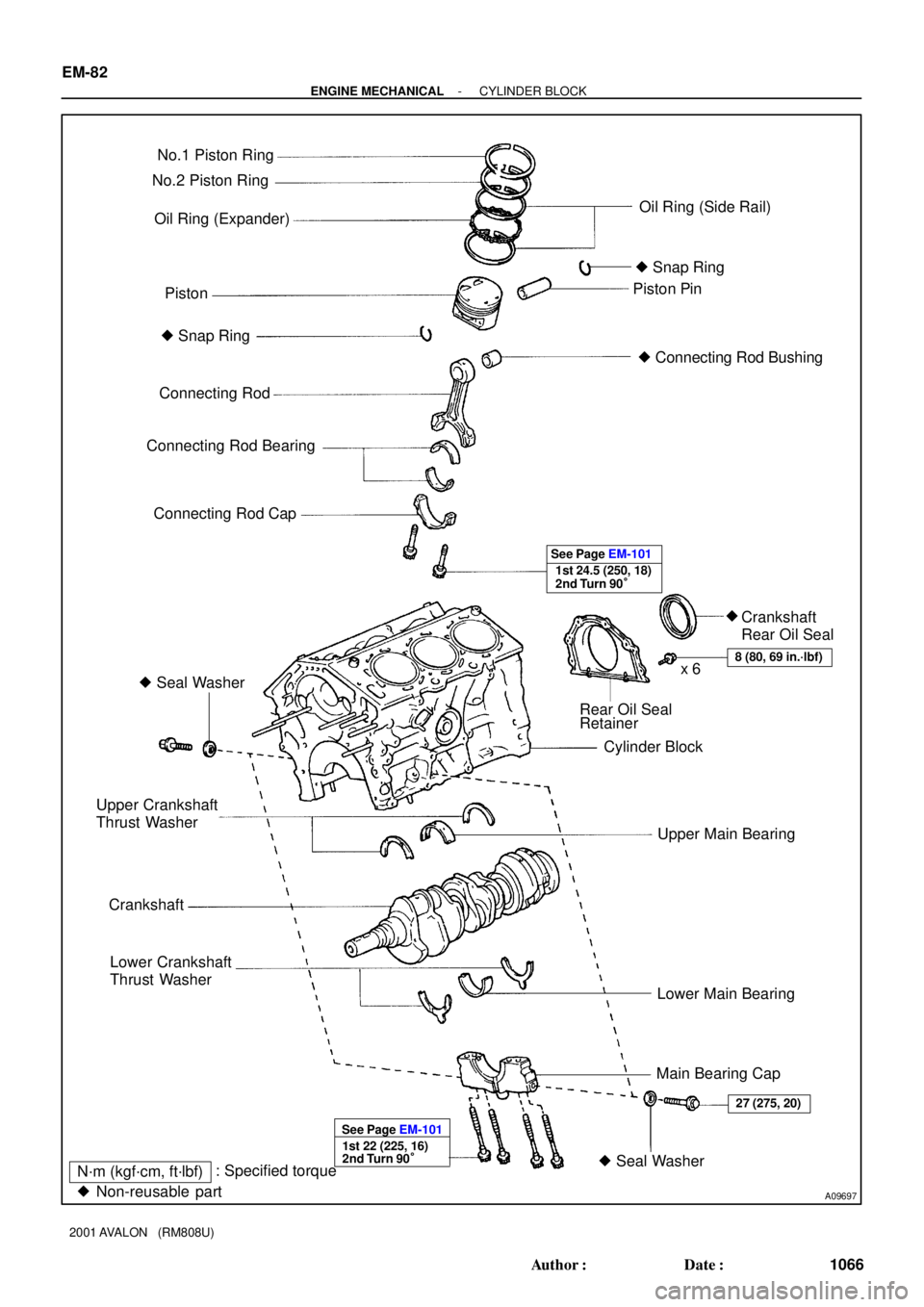
CYLINDER BLOCK
COMPONENTS
Page 1290 of 1897
A09697
No.1 Piston Ring
Oil Ring (Expander)
PistonPiston Pin No.2 Piston Ring
Oil Ring (Side Rail)
� Snap Ring
� Connecting Rod Bushing � Snap Ring
Connecting Rod
Connecting Rod Bearing
Connecting Rod Cap
1st 24.5 (250, 18)
2nd Turn 90° See Page EM-101
� Seal Washer
Rear Oil Seal
Retainer
Cylinder Block
Upper Main Bearing
Lower Main Bearing
Main Bearing Cap Upper Crankshaft
Thrust Washer
Crankshaft
Lower Crankshaft
Thrust Washer
8 (80, 69 in.´lbf)x 6
1st 22 (225, 16)
2nd Turn 90° See Page EM-101
� Seal Washer
27 (275, 20)
N´m (kgf´cm, ft´lbf): Specified torque
� Non-reusable part
Crankshaft
Rear Oil Seal � EM-82
- ENGINE MECHANICALCYLINDER BLOCK
1066 Author�: Date�:
2001 AVALON (RM808U)
Page 1291 of 1897

DISASSEMBLY
1. REMOVE DRIVE PLATE
Remove the 8 bolts, rear plate, drive plate a")
A05415
EM0ZN-02
S04921
A05252
P18761
- ENGINE MECHANICALCYLINDER BLOCK
EM-83
1067 Author�: Date�:
2001 AVALON (RM808U)
DISASSEMBLY
1. REMOVE DRIVE PLATE
Remove the 8 bolts, rear plate, drive plate and front spacer.
2. INSTALL ENGINE TO ENGINE STAND FOR DIS-
ASSEMBLY
3. REMOVE TIMING BELT AND PULLEYS
(See page EM-15)
4. REMOVE CYLINDER HEAD (See page EM-31)
5. DISCONNECT CRANKSHAFT POSITION SENSOR
CONNECTOR
6. DISCONNECT OIL PRESSURE SWITCH CONNECTOR
7. DISCONNECT OIL LEVEL SENSOR CONNECTOR
8. REMOVE ENGINE WIRE
(a) Disconnect the 2 wire clamps from the wire brackets.
(b) Remove the 2 bolts and nut, and disconnect the engine
wire.
9. REMOVE GENERATOR, ADJUSTING BAR AND
BRACKET ASSEMBLY
Remove the 3 nuts, the generator, adjusting bar and bracket as-
sembly.
10. REMOVE OIL PRESSURE SWITCH
(See page LU-1)
11. REMOVE A/C COMPRESSOR HOUSING BRACKET
Remove the 2 bolts and compressor housing bracket.
12. REMOVE NO.2 IDLER PULLEY BRACKET
Remove the 2 bolts and idler pulley bracket.
Page 1292 of 1897

13.")
P12389
SST
A05253
P18763
WaterSeal
Plate
Oil Filter
Union
12 mm
Hexagon
Wrench
Coolant
Drain
Union
A02010
P12508
EM-84
- ENGINE MECHANICALCYLINDER BLOCK
1068 Author�: Date�:
2001 AVALON (RM808U)
13. REMOVE KNOCK SENSORS
(a) Disconnect the 2 knock sensor connectors.
(b) Using SST, remove the 2 knock sensors.
SST 09816-30010
14. REMOVE WATER INLET HOUSING
(a) Remove the engine wire band.
(b) Disconnect the engine wire clamp from the bracket.
(c) Remove the 8 bolts, 2 nuts and water inlet housing.
15. REMOVE WATER PUMP (See page CO-6)
16. REMOVE NO.2 OIL PAN (See page LU-9)
17. REMOVE OIL STRAINER (See page LU-3)
18. REMOVE NO.1 OIL PAN (See page LU-3)
19. REMOVE OIL PUMP (See page LU-9)
20. REMOVE OIL FILTER (See page LU-3)
21. REMOVE OIL FILTER UNION
Using a 12 mm hexagon wrench, remove the oil filter union.
22. REMOVE WATER SEAL PLATE
Remove the 2 nuts and seal plate.
23. REMOVE ENGINE COOLANT DRAIN UNION
24. REMOVE CYLINDER BLOCK SIDE COVER
Remove the 3 bolts, 2 nuts, cylinder block side cover and gas-
ket.
25. REMOVE REAR OIL SEAL RETAINER
(a) Remove the 6 bolts.
(b) Using a screwdriver, remove the oil seal retainer by prying
the portions between the oil seal retainer and main bear-
ing cap.
Page 1293 of 1897

26. CHECK CONNECTING ROD THRUST CLEARANCE
Using a dial indicator, measure the thrust cle")
P12695
A09694
P12707
P12696
- ENGINE MECHANICALCYLINDER BLOCK
EM-85
1069 Author�: Date�:
2001 AVALON (RM808U)
26. CHECK CONNECTING ROD THRUST CLEARANCE
Using a dial indicator, measure the thrust clearance while mov-
ing the connecting rod back and forth.
Standard thrust clearance:
0.15 - 0.30 mm (0.0059 - 0.0118 in.)
Maximum thrust clearance: 0.35 mm (0.0138 in.)
If the thrust clearance is greater than maximum, replace the
connecting rod assembly(s). If necessary, replace the crank-
shaft.
Connecting rod thickness:
20.80 - 20.85 mm (0.8189 - 0.8209 in.)
27. REMOVE CONNECTING ROD CAPS AND CHECK OIL
CLEARANCE
(a) Check the matchmarks on the connecting rod and cap are
aligned to ensure correct reassembly.
(b) Remove the 2 connecting rod cap bolts.
(c) Using the 2 removed connecting rod cap bolts, remove
the connecting rod cap and lower bearing by wiggling the
connecting rod cap right and left.
HINT:
Keep the lower bearing inserted with the connecting rod cap.
(d) Clean the crank pin and bearing.
(e) Check the crank pin and bearing for pitting and scratches.
If the crank pin or bearing is damaged, replace the bearings. If
necessary, replace the crankshaft.