Page 1317 of 1897
P12570
SST
P12808
Cut Position
P12810
SST EM-100
- ENGINE MECHANICALCYLINDER BLOCK
1084 Author�: Date�:
2001 AVALON (RM808U)
(2) Using SST and a hammer, tap in a new oil seal until
its surface is flush with the rear oil seal retainer
edge.
SST 09223-15030, 09950-70010 (09951-07100)
(3) Apply MP grease to the oil seal lip.
(b) If the rear oil seal retainer is installed to the cylinder block.
(1) Using a knife, cut off the oil seal lip.
(2) Using a screwdriver, pry out the oil seal.
NOTICE:
Be careful not to damage the crankshaft. Tape the screw-
driver tip.
(3) Apply MP grease to a new oil seal lip.
(4) Using SST and a hammer, tap in the oil seal until its
surface is flush with the rear oil seal retainer edge.
SST 09223-15030, 09950-70010 (09951-07100)
Page 1319 of 1897
Water Bypass Hose
A10522
PS Pressure Tube
Throttle Body Bracket
Engine WireThrottle Position
Sensor Connector
Vacuum Hose Brake Booster
39 (400,29)
IAC Valve
Connector
Accelerator Cable
Purge Hose
Hose Vacuum
�Gasket
VSV Connector for No.2 ACIS
Engine Coolant
Reservoir Hose
43 (440,32)
ECT Sender
Gauge Connector
ECT Sensor
Connector
Grand Strap
Connector
15 (150,11)
Water Outlet
15 (150,11)
Water Bypass
Hose
Upper Radiator
HoseFuel Inlet Hose
Injector Connector Intake Manifold
Assembly
�Retainer
Heater Hose
�GasketIgnition Coil
Connector
� Non-reusable part: Specified torque
N´m (kgf´cm, ft´lbf)
19.5 (200, 14)
No.1 Engine
Hanger
VSV Connector for
EVAP
Ground Cable
PCV Hose Ground Cable
Air Intake Chamber
Assembly
� Gasket
Spark PlugIgnition Coil
Ground Strap
DLC1
Gasket
Fuel Hose Clamp
VSV Connector
for No.1 ACIS
Throttle Cable
- ENGINE MECHANICALCYLINDER HEAD
EM-27
1011 Author�: Date�:
2001 AVALON (RM808U)
Page 1321 of 1897
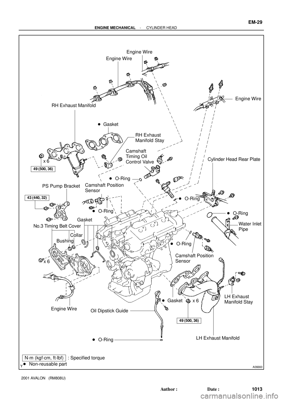
A06660
Engine Wire
Engine Wire
RH Exhaust Manifold
49 (500, 36)
x 6Cylinder Head Rear Plate
PS Pump Bracket
43 (440, 32)
Gasket
No.3 Timing Belt Cover
CollarWater Inlet
Pipe
x 6
� O-Ring Oil Dipstick Guide
N´m (kgf´cm, ft´lbf) : Specified torque
� Non-reusable part� Gasket
Engine Wire
Engine Wire
49 (500, 36)
Bushing
Camshaft Position
Sensor
LH Exhaust
Manifold Stay
x 6
� Gasket
� O-Ring
� O-Ring
LH Exhaust Manifold
� O-Ring
Camshaft
Timing Oil
Control Valve
Camshaft Position
SensorRH Exhaust
Manifold Stay
� O-Ring
� O-Ring
- ENGINE MECHANICALCYLINDER HEAD
EM-29
1013 Author�: Date�:
2001 AVALON (RM808U)
Page 1322 of 1897

A05703
Adjusting Shim
Valve Lifter
Keeper
Spring Retainer
Valve Spring
Spring Seat
� Oil Seal
Valve � Valve Guide BushingLH Cylinder Head Cover
LH Intake
Camshaft
Snap Ring Camshaft Sub-Gear
LH Exhaust
Camshaft RH Cylinder Head Cover
Gasket
RH Intake
Camshaft Camshaft Sub-Gear
Camshaft Gear Spring
RH Exhaust
CamshaftWave Washer
Semi-Circular PlugSemi-Circular
Plug
LH Cylinder Head
Camshaft
Bearing Cap
� Camshaft Oil Seal RH Cylinder Head
� RH Cylinder
Head Gasket
� LH Cylinder Head Gasket18 (185, 13)x 8
16 (160, 12)
See Page EM-59
1st 54 (550, 40)
2nd Turn 90°
N´m (kgf´cm, ft´lbf) : Specified torque
� Non-reusable part
� Spark Plug
Tube Gasket
Wave WasherGasketSnap RingCamshaft Gear Spring
Oil Control Valve Filter
� Gasket
Camshaft Timing
Gear (VVT-i)
� Gasket
� Gasket
Oil Control
Valve FilterCylinder Head
Rear CoverCylinder Head
Rear Cover� Gasket
150 (1,530, 110)
NOTICE:
Intake Camshaft
Do not remove or install the camshaft timing
gear (VVT-i) beside changing VVT-i or the
camshaft.
�
EM-30
- ENGINE MECHANICALCYLINDER HEAD
1014 Author�: Date�:
2001 AVALON (RM808U)
Page 1323 of 1897
EM0ZF-02
P12683
A05224
SST
P12686
P12720
Magnetic Finger
A05276
EM-40
- ENGINE MECHANICALCYLINDER HEAD
1024 Author�: Date�:
2001 AVALON (RM808U)
DISASSEMBLY
1. REMOVE VALVE LIFTERS AND SHIMS
HINT:
Arrange the valve lifters and shims in the correct order.
2. REMOVE VALVES
(a) Using SST, compress the valve spring and remove the 2
keepers.
SST 09202-70020 (09202-00010)
(b) Remove the spring retainer, valve spring and valve.
(c) Using needle-nose pliers, remove the oil seal.
(d) Using compressed air and a magnetic finger, remove the
spring seat by blowing air.
HINT:
Arrange the valves, valve springs, spring seats and spring re-
tainers in the correct order.
3. REMOVE CYLINDER HEAD REAR COVER
Remove the 6 bolts, rear cover and gasket.
Page 1324 of 1897
A05275
- ENGINE MECHANICALCYLINDER HEAD
EM-41
1025 Author�: Date�:
2001 AVALON (RM808U)
4. REMOVE OIL CONTROL VALVE FILTER
Remove the plug, gasket and valve filter.
Page 1325 of 1897

INSPECTION
1. CLEAN TOP SURFACES OF PISTONS AND CYL-
INDER BLOCK
(a) Turn")
A05225
EM0ZG-02
A05226
A05230
A05233
A05232
EM-42
- ENGINE MECHANICALCYLINDER HEAD
1026 Author�: Date�:
2001 AVALON (RM808U)
INSPECTION
1. CLEAN TOP SURFACES OF PISTONS AND CYL-
INDER BLOCK
(a) Turn the crankshaft, and bring each piston to top dead
center (TDC). Using a gasket scraper, remove all the car-
bon from the piston top surface.
(b) Using a gasket scraper, remove all the gasket material
from the cylinder block surface.
(c) Using compressed air, blow carbon and oil from the bolt
holes.
CAUTION:
Protect your eyes when using high pressure compressed
air.
2. REMOVE GASKET MATERIAL
Using a gasket scraper, remove all the gasket material from the
cylinder block contact surface.
NOTICE:
Be careful not to scratch the cylinder block contact sur-
face.
3. CLEAN COMBUSTION CHAMBERS
Using a wire brush, remove all the carbon from the combustion
chambers.
NOTICE:
Be careful not to scratch the cylinder block contact sur-
face.
4. CLEAN CYLINDER HEADS
Using a soft brush and solvent, thoroughly clean the cylinder
head.
Page 1327 of 1897

9. INSPECT VALVE STEMS AND GUIDE BUSHINGS
(a) Using a caliper gau")
P12754
Z00052
Z00054
44.5°
EM0181
Margin Thickness EM-44
- ENGINE MECHANICALCYLINDER HEAD
1028 Author�: Date�:
2001 AVALON (RM808U)
9. INSPECT VALVE STEMS AND GUIDE BUSHINGS
(a) Using a caliper gauge, measure the inside diameter of the
guide bushing.
Bushing inside diameter:
5.510 - 5.530 mm (0.2169 - 0.2177 in.)
(b) Using a micrometer, measure the diameter of the valve
stem.
Valve stem diameter:
Intake5.470 - 5.485 mm (0.2154 - 0.2159 in.)
Exhaust5.465 - 5.480 mm (0.2152 - 0.2157 in.)
(c) Subtract the valve stem diameter measurement from the
guide bushing guide bushing inside diameter measure-
ment.
Standard oil clearance:
Intake0.025 - 0.060 mm (0.0010 - 0.0024 in.)
Exhaust0.030 - 0.065 mm (0.0012 - 0.0026 in.)
Maximum oil clearance:
Intake0.08 mm (0.0031 in.)
Exhaust0.10 mm (0.0039 in.)
If the clearance is greater than maximum, replace the valve and
guide bushing.
10. INSPECT AND GRIND VALVES
(a) Grind the valve enough to remove pits and carbon.
(b) Check that the valve is ground to the correct valve face
angle.
Valve face angle: 44.5°
(c) Check the valve head margin thickness.
Standard margin thickness: 1.0 mm (0.039 in.)
Minimum margin thickness: 0.5 mm (0.020 in.)
If the margin thickness is less than minimum, replace the valve.


IAC Valve
Connector
Accelerator Cable
Purge Hose
Hos")