Page 1382 of 1897
A05056
LH
SST
P18811
A05063
SST
EM-22
- ENGINE MECHANICALTIMING BELT
1006 Author�: Date�:
2001 AVALON (RM808U)
5. INSTALL LH CAMSHAFT TIMING PULLEY
(a) Face the flange side of the timing pulley inward.
(b) Align the knock pin on the camshaft with the knock pin
groove of the timing pulley, and slide on the timing pulley.
(c) Using SST, install the pulley bolt.
SST 09960-10010 (09962-01000, 09963-01000)
Torque: 125 N´m (1,300 kgf´cm, 94 ft´lbf)
6. SET NO.1 CYLINDER TO TDC/COMPRESSION
(a) Crankshaft Timing Pulley Position:
(1) Temporarily install the crankshaft pulley bolt to the
crankshaft.
(2) Turn the crankshaft, and align the timing marks of
the crankshaft timing pulley and oil pump body.
(b) Camshaft Timing Pulley Positions:
Using SST, turn the camshaft pulley, align the timing
marks of the timing pulley and No.3 timing belt cover.
SST 09960-10010 (09962-01000, 09963-01000)
Page 1383 of 1897

7. INSTALL TIMING BELT")
A02338
5th4th3rd
2nd
6th
1st
A05064
1.27 mm
Hexagon
Wrench
A05065
A05066
1.27 mm
Hexagon
Wrench
- ENGINE MECHANICALTIMING BELT
EM-23
1007 Author�: Date�:
2001 AVALON (RM808U)
7. INSTALL TIMING BELT
NOTICE:
The engine should be cold.
(a) Remove any oil or water on the pulleys, and keep them
clean.
NOTICE:
Only wipe the pulleys; do not use any cleansing agent.
(b) Face the front mark on the timing belt forward.
(c) Align the installation mark on the timing belt with the tim-
ing mark of the crankshaft timing pulley.
(d) Align the installation marks on the timing belt with the tim-
ing marks of the camshaft timing pulleys.
(e) Install the timing belt in this order:
1st: Crankshaft timing pulley
2nd: Water pump pulley
3rd: LH camshaft timing pulley
4th: No.2 idler pulley
5th: RH camshaft timing pulley
6th: No.1 idler pulley
8. SET TIMING BELT TENSIONER
(a) Using a press, slowly press in the push rod using 981 -
9,807 N (100 - 1,000 kgf, 200 - 2,205 lbf) of pressure.
(b) Align the holes of the push rod and housing, pass a 1.27
mm hexagon wrench through the holes to keep the set-
ting position of the push rod.
(c) Release the press.
(d) Install the dust boot to the tensioner.
9. INSTALL TIMING BELT TENSIONER
(a) Temporarily install the tensioner with the 2 bolts.
(b) Alternately tighten the 2 bolts.
Torque: 27 N´m (280 kgf´cm, 20 ft´lbf)
(c) Remove the 1.27 mm hexagon wrench from the tension-
er.
Page 1384 of 1897

P18815
EM-24
- ENGINE MECHANICALTIMING BELT
1008 Author�: Date�:
2001 AVALON (RM808U)
10. CHECK VALVE TIMING
(a) Slowly turn the crankshaft 2 revol")
P18808
A05052
P12983
Length = 1,410 mm (55.51 in.)
P18815
EM-24
- ENGINE MECHANICALTIMING BELT
1008 Author�: Date�:
2001 AVALON (RM808U)
10. CHECK VALVE TIMING
(a) Slowly turn the crankshaft 2 revolutions, and align the tim-
ing marks of the crankshaft timing pulley and oil pump
body.
NOTICE:
Always turn the crankshaft clockwise.
(b) Check that the timing marks of the RH and LH timing pul-
leys with the timing marks of the No.3 timing belt cover as
shown in the illustration.
If the marks do not align, remove the timing belt and reinstall it.
(c) Remove the crankshaft pulley bolt.
11. INSTALL RH ENGINE MOUNTING BRACKET
Torque: 28 N´m (290 kgf´cm, 21 ft´lbf)
12. INSTALL NO.2 TIMING BELT COVER
(a) Check that the timing belt cover gasket has no cracks or
peeling, etc.
If the gasket has cracks or peeling, etc., replace it using these
steps:
�Using a screwdriver and gasket scraper, remove all
the old gasket material.
�Thoroughly clean all components to remove all the
loose material.
�Remove the backing paper from a new gasket and
install the gasket evenly to the part of the timing belt
cover shaded black in the illustration.
�After installing the gasket, press down on it so that
the adhesive firmly sticks to the timing belt cover.
(b) Install the timing belt cover with the 5 bolts.
Torque: 8.5 N´m (85 kgf´cm, 74 in.´lbf)
(c) Install the engine wire protector clamps to the No.3 timing
belt cover.
13. INSTALL TIMING BELT GUIDE
Install the timing belt guide, facing the cup side outward.
Page 1387 of 1897
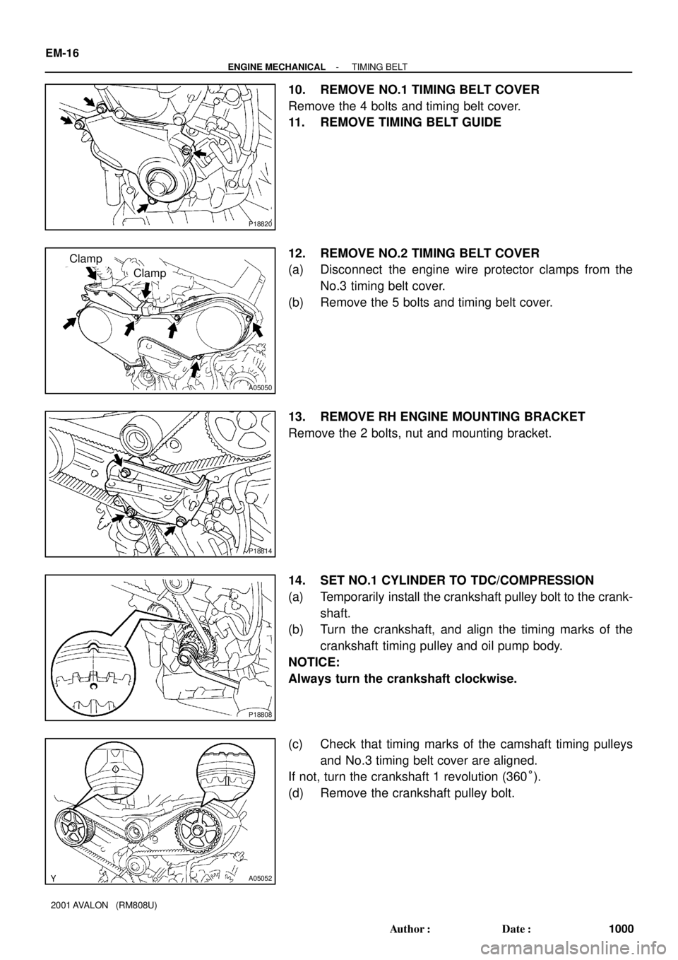
P18820
A05050
Clamp
Clamp
P18814
P18808
A05052
EM-16
- ENGINE MECHANICALTIMING BELT
1000 Author�: Date�:
2001 AVALON (RM808U)
10. REMOVE NO.1 TIMING BELT COVER
Remove the 4 bolts and timing belt cover.
11. REMOVE TIMING BELT GUIDE
12. REMOVE NO.2 TIMING BELT COVER
(a) Disconnect the engine wire protector clamps from the
No.3 timing belt cover.
(b) Remove the 5 bolts and timing belt cover.
13. REMOVE RH ENGINE MOUNTING BRACKET
Remove the 2 bolts, nut and mounting bracket.
14. SET NO.1 CYLINDER TO TDC/COMPRESSION
(a) Temporarily install the crankshaft pulley bolt to the crank-
shaft.
(b) Turn the crankshaft, and align the timing marks of the
crankshaft timing pulley and oil pump body.
NOTICE:
Always turn the crankshaft clockwise.
(c) Check that timing marks of the camshaft timing pulleys
and No.3 timing belt cover are aligned.
If not, turn the crankshaft 1 revolution (360°).
(d) Remove the crankshaft pulley bolt.
Page 1390 of 1897

VALVE CLEARANCE
INSPECTION
HINT:
Inspect and adjust")
EM03V-03
P18805
A05273
RH EX
RH IN
LH IN
LH EX 3 3
11Front
2266 EM-4
- ENGINE MECHANICALVALVE CLEARANCE
988 Author�: Date�:
2001 AVALON (RM808U)
VALVE CLEARANCE
INSPECTION
HINT:
Inspect and adjust the valve clearance when the engine is cold.
1. REMOVE RH FENDER APRON SEAL
2. DRAIN ENGINE COOLANT
3. REMOVE V-BANK COVER
(a) Using a 5 mm hexagon wrench, remove the 3 cap nuts.
(b) Loosen the V-bank cover fastener counterclockwise.
(c) Remove the V-bank cover.
4. REMOVE AIR INTAKE CHAMBER ASSEMBLY (See
page EM-31)
5. REMOVE IGNITION COILS
6. DISCONNECT UPPER RADIATOR HOSE FROM WA-
TER OUTLET
7. REMOVE CYLINDER HEAD COVERS
(See page EM-31)
8. SET NO.1 CYLINDER TO TDC/COMPRESSION
(a) Turn the crankshaft pulley, and align its groove with the
timing mark º0º of the No.1 timing belt cover.
(b) Check that the valve lifters on the No.1 (IN and EX) are
loose.
If not, turn the crankshaft 1 revolution (360°) and align the mark
as above.
9. INSPECT VALVE CLEARANCE
(a) Check only those valves indicated in the illustration.
(1) Using a feeler gauge, measure the clearance be-
tween the valve lifter and camshaft.
(2) Record out of specification valve clearance mea-
surements. They will be used later to determine the
required replacement adjusting shim.
Valve clearance (Cold):
Intake0.15 - 0.25 mm (0.006 - 0.010 in.)
Exhaust0.25 - 0.35 mm (0.010 - 0.014 in.)
Page 1393 of 1897
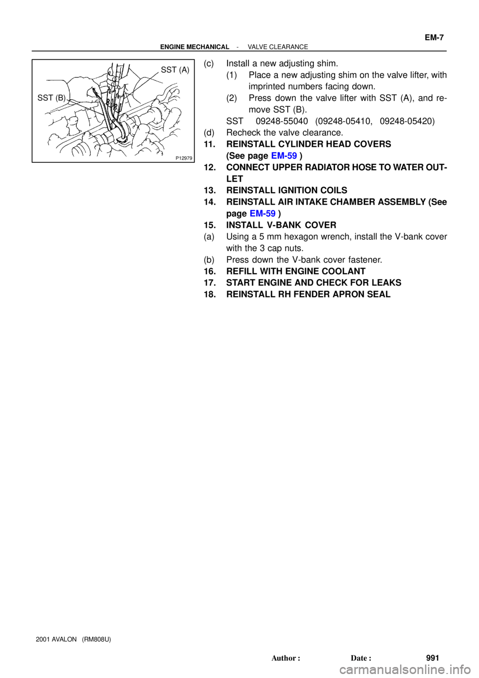
P12979
SST (A)
SST (B)
- ENGINE MECHANICALVALVE CLEARANCE
EM-7
991 Author�: Date�:
2001 AVALON (RM808U)
(c) Install a new adjusting shim.
(1) Place a new adjusting shim on the valve lifter, with
imprinted numbers facing down.
(2) Press down the valve lifter with SST (A), and re-
move SST (B).
SST 09248-55040 (09248-05410, 09248-05420)
(d) Recheck the valve clearance.
11. REINSTALL CYLINDER HEAD COVERS
(See page EM-59)
12. CONNECT UPPER RADIATOR HOSE TO WATER OUT-
LET
13. REINSTALL IGNITION COILS
14. REINSTALL AIR INTAKE CHAMBER ASSEMBLY (See
page EM-59)
15. INSTALL V-BANK COVER
(a) Using a 5 mm hexagon wrench, install the V-bank cover
with the 3 cap nuts.
(b) Press down the V-bank cover fastener.
16. REFILL WITH ENGINE COOLANT
17. START ENGINE AND CHECK FOR LEAKS
18. REINSTALL RH FENDER APRON SEAL
Page 1400 of 1897
IG09O-03
B07460
V-Bank Cover
Ignition Coil
(w/ Igniter) Ignition Coil
Connector
Gasket
8 (80, 69 in.´lbf)
N´m (kgf´cm, ft´lbf) : Specified torque
IG-4
- IGNITIONIGNITION COIL
1247 Author�: Date�:
2001 AVALON (RM808U)
IGNITION COIL
COMPONENTS
Page 1401 of 1897
IG0DM-02
A10518
5 mm
Hexagon
Wrench
B06515
- IGNITIONIGNITION COIL
IG-5
1248 Author�: Date�:
2001 AVALON (RM808U)
REPLACEMENT
1. REMOVE V-BANK COVER
(a) Using a 5 mm hexagon wrench, remove the 3 cap nuts.
(b) Loosen the V-bank cover fastener counterclockwise.
(c) Remove the V-bank cover.
2. REMOVE IGNITION COILS
(a) Disconnect the 6 ignition coil connectors.
(b) Remove the bolt, and pull out the ignition coil. Remove
the 6 ignition coils.
3. REINSTALL NEW IGNITION COILS
(a) Connect a new ignition coil to the spark plug, and attach
the ignition coil to the cylinder head cover, and install the
bolt. Install the 6 ignition coils.
Torque: 8 N´m (80 kgf´cm, 69 in.´lbf)
(b) Connect the 6 ignition coil connectors.
4. REINSTALL V-BANK COVER
(a) Using 5 mm hexagon wrench, install the V-bank cover
with the 3 cap nuts.
(b) Press down the V-bank cover fastener.