Page 500 of 1897

DISASSEMBLY
1. REMOVE RESERVOIR
(a) Remove the set screw and pull out")
BR0KS-03
F09715
Soft Jows
F09716
Soft Jows
R12236
A BR-16
- BRAKEBRAKE MASTER CYLINDER
1415 Author�: Date�:
2001 AVALON (RM808U)
DISASSEMBLY
1. REMOVE RESERVOIR
(a) Remove the set screw and pull out the reservoir.
Torque: 1.7 N´m (17.5 kgf´cm, 15.2 in.´lbf)
(b) Remove the cap and strainer from the reservoir.
2. REMOVE 2 GROMMETS
3. w/o VSC:
PLACE CYLINDER IN VISE
4. w/o VSC:
REMOVE PISTON STOPPER BOLT
Using a screwdriver, push the pistons in all the way and remove
the piston stopper bolt and gasket.
HINT:
Tape the screwdriver tip before use.
Torque: 10 N´m (100 kgf´cm, 7 ft´lbf)
5. w/o VSC:
REMOVE 2 PISTONS AND SPRINGS
(a) Push in the piston with a screwdriver and remove the
snap ring with snap ring pliers.
HINT:
Tape the screwdriver tip before use.
(b) Remove the No. 1 piston and spring by hand, pulling
straight out, not at an angle.
NOTICE:
�If pulled out and install at an angle, there is a possibil-
ity that the cylinder bore could be damaged.
�At the time of reassembly, be careful not to damage
the rubber lips on the pistons.
(c) Place a rag and 2 wooden blocks on the work table, and
lightly tap the cylinder flange against the block edges until
the No. 2 piston drops out of the cylinder.
HINT:
Make sure that the distance (A) from the rag to the top of the
blocks is at least 100 mm (3.94 in.).
Page 505 of 1897
BR0KR-02
F09713SST
F09714
- BRAKEBRAKE MASTER CYLINDER
BR-15
1414 Author�: Date�:
2001 AVALON (RM808U)
REMOVAL
1. REMOVE AIR CLEANER COVER WITH AIR CLEANER
HOSE
2. TAKE OUT FLUID WITH SYRINGE
NOTICE:
Do not let brake fluid remain on a painted surface. Wash it
off immediately.
3. DISCONNECT LEVEL WARNING SWITCH CONNEC-
TOR
4. w/ VSC:
DISCONNECT RESERVOIR HOSE
5. DISCONNECT BRAKE LINES
(a) w/o VSC:
Using SST, disconnect the 4 brake lines from the master
cylinder and 2-way.
SST 09023-00100
Torque: 15 N´m (155 kgf´cm, 11 ft´lbf)
(b) w/ VSC:
Using SST, disconnect the 5 brake lines from the master
cylinder and 3-way.
SST 09023-00100
Torque: 15 N´m (155 kgf´cm, 11 ft´lbf)
6. REMOVE MASTER CYLINDER
Remove the 2 mounting nuts, and pull out the 2 or 3-way, mas-
ter cylinder and gasket.
Torque: 13 N´m (130 kgf´cm, 9 ft´lbf)
Page 507 of 1897
(+)
- BRAKEBRAKE FLUID
BR-5
1404 Author�: Date�:
2001 AVALON (RM808U)
(b) While an assistant depresses the pedal, loosen the
bleeder plug until fluid starts to run out. Then")
F10182
SST
F07901
2 1
(-)(+)
- BRAKEBRAKE FLUID
BR-5
1404 Author�: Date�:
2001 AVALON (RM808U)
(b) While an assistant depresses the pedal, loosen the
bleeder plug until fluid starts to run out. Then tighten the
bleeder plug.
(c) Repeat this procedure until there are no more air bubbles
in the fluid.
Bleeder plug tightening torque:
8.3 N´m (85 kgf´cm, 74 in.´lbf)
5. REPEAT PROCEDURE FOR EACH WHEEL
6. w/ VSC:
BLEED PRECHARGE PUMP
CAUTION:
When repairing the brake master cylinder or precharge
pump, bleed the precharge pump of the air.
(a) Install the SST to the reservoir.
SST 09992-00242, 09992-00350
(b) Using SST, apply pressure to the reservoir.
Pressure: 98.1 kpa (1.0 kgf/cm
2, 14.2 psi)
(c) Disconnect the precharge pump connector.
(d) Connect ML+ (2) terminal to the battery positive (+) and
ML- (1) terminal to the battery negative (-), and activate
the precharge pump about 20 seconds.
(e) Remove the SST from the reservoir.
(f) Connect the vinyl tube to the front brake caliper RH, and
loosen the bleeder plug.
(g) Activate the precharge pump again until there are no
more air bubbles in the fluid.
Bleeder plug tightening torque:
8.3 N´m (85 kgf´cm, 74 in.´lbf)
(h) Connect the precharge pump connector.
7. CHECK FLUID LEVEL IN RESERVOIR
Check the fluid level and add fluid if necessary.
Fluid: SAE J1703 or FMVSS No. 116 DOT3
Page 508 of 1897
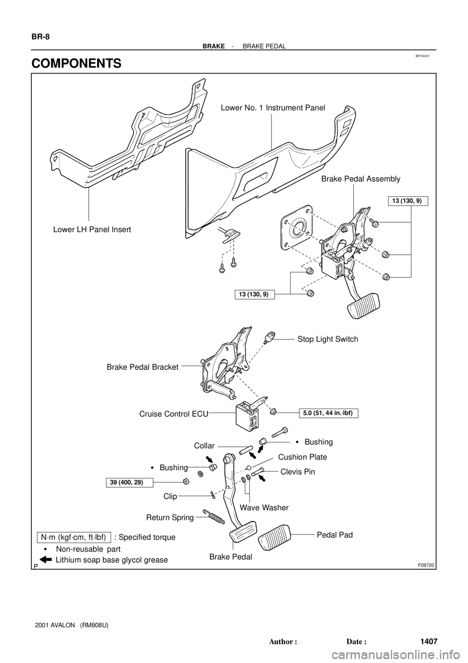
BR150-01
F09720
Brake Pedal Bracket Lower LH Panel Insert
Lower No. 1 Instrument Panel
Stop Light Switch
Cruise Control ECU
Pedal Pad
Clip
Return Spring
Collar
Wave Washer
Clevis Pin
Cushion Plate
� Bushing
� Bushing
Brake Pedal
Lithium soap base glycol grease
Non-reusable part �
Brake Pedal Assembly
N´m (kgf´cm, ft´lbf) : Specified torque
13 (130, 9)
39 (400, 29)
13 (130, 9)
5.0 (51, 44 in.´lbf)
BR-8
- BRAKEBRAKE PEDAL
1407 Author�: Date�:
2001 AVALON (RM808U)
COMPONENTS
Page 509 of 1897

BRAKE PEDAL
ON-VEHICLE INSPECTION
1. CHECK PEDAL HEIGH")
R00954
Stop Light Switch
Push Rod
Pedal HeightBR0KI-04
R00935
Pedal Freeplay BR-6
- BRAKEBRAKE PEDAL
1405 Author�: Date�:
2001 AVALON (RM808U)
BRAKE PEDAL
ON-VEHICLE INSPECTION
1. CHECK PEDAL HEIGHT
Pedal height from asphalt sheet:
153.3 - 163.3 mm (6.035 - 6.429 in.)
If the pedal height is incorrect, adjust it.
2. IF NECESSARY, ADJUST PEDAL HEIGHT
(a) Remove the lower No. 1 instrument panel and lower LH
instrument panel insert (See page BO-87).
(b) Disconnect the connector from the stop light switch.
(c) Loosen the stop light switch lock nut and remove the stop
light switch.
(d) Loosen the push rod lock nut.
(e) Adjust the pedal height by turning the pedal push rod.
(f) Tighten the push rod lock nut.
Torque: 25 N´m (260 kgf´cm, 19 ft´lbf)
(g) Install the stop light switch.
(h) Connect the connector to the stop light switch.
(i) Push the brake pedal in 5 - 15 mm (0.20 - 0.59 in.), turn
the stop light switch to lock the nut in the position where
the stop light goes off.
(j) After installation, push the brake pedal in 5 - 15 mm (0.20
- 0.59 in.), check that stop light lights up.
(k) After adjusting the pedal height, check the pedal freeplay.
(l) Install the lower LH instrument panel insert and lower No.
1 instrument panel (See page BO-87).
3. CHECK PEDAL FREEPLAY
(a) Stop the engine and depress the brake pedal several
times until there is no more vacuum left in the booster.
(b) Push in the pedal by hand until the beginning of the resis-
tance is felt, then measure the distance.
Pedal freeplay: 1 - 6 mm (0.04 - 0.24 in.)
If incorrect, check the stop light switch clearance. If the clear-
ance is OK, then troubleshoot the brake system.
Stop light switch clearance:
0.5 - 2.4 mm (0.020 - 0.094 in.)
HINT:
The freeplay to the 1st resistance is due to the play between the
clevis and pin. This is magnified up to 1 - 6 mm (0.04 - 0.24 in.)
at the pedal.
Page 512 of 1897
BR0L2-04
F06986
Caliper
Torque Plate
Disc
Gasket
Sliding Bushing
Dust Boot Sliding Pin
Piston Bleeder Plug
Piston Seal
Boot
Dust BootPad Support Plate
Anti-squeal Shim Inner Anti-squeal Shim Inner Pad
Outer Pad Pad Wear Indicator Plate
Sliding Pin
�
�
�
�Set Ring
Disc brake grease Lithium soap base glycol grease Non-reusable part
N´m (kgf´cm, ft´lbf): Specified torque
�
107 (1,090, 79)
8.3 (85, 74 in.´lbf)
34 (350, 25)
29 (300, 22)
29 (300, 22)
Anti-squeal Shim
Inner Anti-squeal Shim
BR-28
- BRAKEFRONT BRAKE CALIPER
1427 Author�: Date�:
2001 AVALON (RM808U)
FRONT BRAKE CALIPER
COMPONENTS
Page 513 of 1897

DISASSEMBLY
1. REMOVE SET RING AND CYLINDER BOOT
Using a screwdriver, remove the set r")
BR0L4-04
R00121
R00122
R00123
R02877
BR-30
- BRAKEFRONT BRAKE CALIPER
1429 Author�: Date�:
2001 AVALON (RM808U)
DISASSEMBLY
1. REMOVE SET RING AND CYLINDER BOOT
Using a screwdriver, remove the set ring and cylinder boot from
the caliper.
2. REMOVE PISTON
(a) Place a piece of cloth or similar, between the piston and
the caliper.
(b) Use compressed air to remove the piston from the cylin-
der.
CAUTION:
Do not place your fingers in front of the piston when using
compressed air.
3. REMOVE PISTON SEAL
Using a screwdriver, remove the piston seals from the cylinder.
4. REMOVE SLIDING PINS AND DUST BOOTS
(a) Remove the 2 sliding pins from the torque plate.
NOTICE:
At the time of reassembly, insert the sliding pin with sliding
bushing into the top side.
(b) Using a screwdriver and hammer, tap out the 2 dust
boots.
HINT:
At the time of reaseembly, use a 24 mm socket wrench and tap
in 2 new dust boots into the torque plate.
NOTICE:
At the time of reassembly, confirm that the metal plate por-
tion of the dust boot fits snugly in the torque plate.
Page 514 of 1897

INSPECTION
1. MEASURE PAD LINING THICKNESS
Using a ruler, measure the pad lining thick")
BR0L5-04
F06988
F06395
F06396
F06397
- BRAKEFRONT BRAKE CALIPER
BR-31
1430 Author�: Date�:
2001 AVALON (RM808U)
INSPECTION
1. MEASURE PAD LINING THICKNESS
Using a ruler, measure the pad lining thickness.
Standard thickness: 11.0 mm (0.433 in.)
Minimum thickness: 1.0 mm (0.039 in.)
Replace the pad if the pad's thickness is at the minimum thick-
ness or less, or if the pad has severe, uneven wear.
2. MEASURE DISC THICKNESS
Using a micrometer, measure the disc thickness.
Standard thickness: 28.0 mm (1.102 in.)
Minimum thickness: 26.0 mm (1.024 in.)
Replace the disc if the disc's thickness is at the minimum thick-
ness or less. Replace the disc or grind it on a lathe if it is badly
scored or worn unevenly.
3. MEASURE DISC RUNOUT
Using a dial indicator, measure the disc runout 10 mm (0.39 in.)
from the outer edge of the disc.
Maximum disc runout: 0.05 mm (0.0020 in.)
If the disc's runout is at the maximum value or greater, check the
bearing play in the axial direction and check the axle hub runout
(See page SA-9). If the bearing play and axle hub runout are
not abnormal, adjusting the disc runout or grind it on a ºOn-Carº
brake lathe.
4. IF NECESSARY, ADJUST DISC RUNOUT
(a) Remove the mounting bolts and torque plate from the
knuckle.
(b) Remove the hub nuts and the disc. Reinstall the disc 1/5
of a turn round from its original position on the hub. Install
and torque the hub nuts.
Torque: 103 N´m (1,050 kgf´cm, 76 ft´lbf)
Remeasure the disc runout. Make a note of the runout
and the disc's position on the hub.
(c) Repeat (b) until the disc has been installed on the 3 re-
maining hub positions.
(d) If the minimum runout recorded in (b) and (c) is less than
0.05 mm (0.0020 in.), install the disc in that position.
(e) If the minimum runout recorded in (b) and (c) is greater
than 0.05 mm (0.0020 in.), replace the disc and repeat
step 3.
(f) Install the torque plate and torque the mounting bolts.
Torque: 107 N´m (1,090 kgf´cm, 79 ft´lbf)