Page 486 of 1897
BR0LN-03
W03326
- BRAKEABS ACTUATOR
BR-49
1448 Author�: Date�:
2001 AVALON (RM808U)
DISASSEMBLY
1. DISCONNECT CONNECTOR
2. REMOVE ECU
(a) Using a T20 torx wrench, loosen the 6 screws.
Torque: 3.0 N´m (31 kgf´cm, 27 in.´lbf)
NOTICE:
At the time of reassembly, tighten the screws according to
the order shown on the left.
(b) Remove the ECU and spring plate from the actuator.
NOTICE:
Protect the actuator in order to prevent sealing surface
from getting dirty and causing damage on the valve body.
If the dirt and the like are stuck to the sealing surface, use
plastic tools or soft objects to remove the dirt. Do not use
chemical solvents.
Page 489 of 1897
BR154-01
F09732
1
2
F09733
F09734
BR-48
- BRAKEABS ACTUATOR
1447 Author�: Date�:
2001 AVALON (RM808U)
REMOVAL
1. REMOVE AIR CLEANER ASSEMBLY
2. DISCONNECT CONNECTOR
Pull out the release bar, and disconnect the connector.
3. DISCONNECT BRAKE LINES
Using SST, disconnect the 6 brake lines from the ABS actuator.
SST 09023-00100
Torque: 15 N´m (155 kgf´cm, 11 ft´lbf)
4. REMOVE ABS ACTUATOR ASSEMBLY
Remove the 3 bolts and ABS actuator assembly.
Torque: 19 N´m (195 kgf´cm, 14 ft´lbf)
5. REMOVE ABS ACTUATOR
(a) Remove the 2 nuts and ABS actuator.
Torque: 13 N´m (130 kgf´cm, 9 ft´lbf)
(b) Remove the 2 holders and 3 cushions from the ABS ac-
tuator.
Page 490 of 1897
BR156-01
F09735N´m (kgf´cm, ft´lbf) : Specified torqueAir Cleaner Assembly
Actuator Bracket
ABS & VSC Actuator
ABS & VSC Actuator Assembly
Cushion
Cushion
Holder
15 (155, 11)
15 (155, 11)
13 (130, 9)
Holder
19 (195, 14)
19 (195, 14)
13 (130, 9)
- BRAKEABS & VSC ACTUATOR
BR-53
1452 Author�: Date�:
2001 AVALON (RM808U)
COMPONENTS
Page 493 of 1897
BR157-01
F09736
F09737
BR-54
- BRAKEABS & VSC ACTUATOR
1453 Author�: Date�:
2001 AVALON (RM808U)
REMOVAL
1. REMOVE AIR CLEANER ASSEMBLY
2. DISCONNECT ABS & VSC ACTUATOR CONNECTOR
3. DISCONNECT BRAKE LINES
Using SST, disconnect the 6 brake lines from the ABS & VSC
actuator.
SST 09023-00100
Torque: 15 N´m (155 kgf´cm, 11 ft´lbf)
4. REMOVE ABS & VSC ACTUATOR ASSEMBLY
Remove the 3 bolts and ABS & VSC actuator assembly.
Torque: 19 N´m (195 kgf´cm, 14 ft´lbf)
5. REMOVE ABS & VSC ACTUATOR
(a) Remove the 2 nuts and ABS & VSC actuator from the
bracket.
Torque: 13 N´m (130 kgf´cm, 9 ft´lbf)
(b) Remove the 2 holders and 3 cushions from the ABS &
VSC actuator.
Page 494 of 1897
BR0KX-04
F09719
Air Cleaner with Air Cleaner Hose
Vacuum Hose
Master Cylinder
Brake Booster AssemblyReturn Spring
Lower LH Instrument
Panel Insert
Lower No. 1 Instrument
Panel
No. 2 Heater to Register DuctCleviseClip Wave Washer
Gasket 2-way
w/ VSC:�
15 (155, 11)
13 (130, 9)
13 (130, 9)
13 (130, 9)15 (155, 11)
19 (195, 14)
N´m (kgf´cm, ft´lbf) : Specified torque
� Non-reusable part
19 (195, 14)
Precharge Pump Assembly
Level Warning Switch
Connetor
Pin
12 (260, 19)
BR-22
- BRAKEBRAKE BOOSTER ASSEMBLY
1421 Author�: Date�:
2001 AVALON (RM808U)
COMPONENTS
Page 495 of 1897

BR152-01
F05420
SST Master
Cylinder
F05422
SST
F05421
SST
BR-24
- BRAKEBRAKE BOOSTER ASSEMBLY
1423 Author�: Date�:
2001 AVALON (RM808U)
INSTALLATION
1. INSTALL BRAKE BOOSTER
(a) Install the booster and a new gasket.
(b) Install the clevis to the operating rod.
(c) Install and torque the booster installation nuts.
Torque: 13 N´m (130 kgf´cm, 9 ft´lbf)
(d) Install the clevis pin into the clevis and brake pedal, and
install the clip to the clevis pin.
(e) Install the pedal return spring.
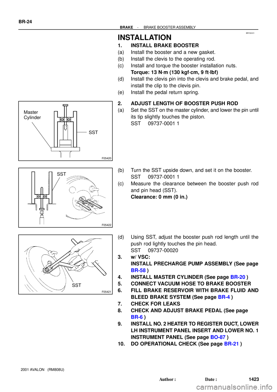
2. ADJUST LENGTH OF BOOSTER PUSH ROD
(a) Set the SST on the master cylinder, and lower the pin until
its tip slightly touches the piston.
SST 09737-0001 1
(b) Turn the SST upside down, and set it on the booster.
SST 09737-0001 1
(c) Measure the clearance between the booster push rod
and pin head (SST).
Clearance: 0 mm (0 in.)
(d) Using SST, adjust the booster push rod length until the
push rod lightly touches the pin head.
SST 09737-00020
3. w/ VSC:
INSTALL PRECHARGE PUMP ASSEMBLY (See page
BR-58)
4. INSTALL MASTER CYLINDER (See page BR-20)
5. CONNECT VACUUM HOSE TO BRAKE BOOSTER
6. FILL BRAKE RESERVOIR WITH BRAKE FLUID AND
BLEED BRAKE SYSTEM (See page BR-4)
7. CHECK FOR LEAKS
8. CHECK AND ADJUST BRAKE PEDAL (See page
BR-6)
9. INSTALL NO. 2 HEATER TO REGISTER DUCT, LOWER
LH INSTRUMENT PANEL INSERT AND LOWER NO. 1
INSTRUMENT PANEL (See page BO-87)
10. DO OPERATIONAL CHECK (See page BR-21)
Page 498 of 1897
BR0KQ-04
F09712
3-way
2-wayMaster CylinderAir Cleaner Cover with
Air Cleaner Hose
Brake Booster
N´m (kgf´cm, ft´lbf) : Specified torquew/ VSC:
15 (155, 11)
13 (130, 9)
15 (155, 11)
13 (130, 9)
Level Warning Switch Connetor
- BRAKEBRAKE MASTER CYLINDER
BR-13
1412 Author�: Date�:
2001 AVALON (RM808U)
BRAKE MASTER CYLINDER
COMPONENTS
Page 499 of 1897
F09748
Cap
Strainer
Reservoir Reservoir Set Screw
Grommet
Cylinder Body
� Gasket
Stopper BoltNo. 1 Piston and Spring
No. 2 Piston and SpringSnap Ring
Grommet w/o VSC:
Cap
Strainer
Reservoir
Grommet Reservoir Set Screw
Grommet
Cylinder Body Straight Pin
� Non-reusable part
Lithium soap base giycol grease
w/ VSC:
1.7 (17.5, 15.2 in.´lbf)
10 (100, 7)
1.7 (17.5, 15.2 in.´lbf)
N´m (kgf´cm, ft´lbf) : Specified torque
O-Ring �
O-Ring �
No. 1 Piston and Spring
No. 2 Piston and SpringSnap Ring
BR-14
- BRAKEBRAKE MASTER CYLINDER
1413 Author�: Date�:
2001 AVALON (RM808U)