Page 530 of 1897

PARKING BRAKE PEDAL
ON-VEHICLE INSPECTION
1. C")
R00254
BR0KJ-02
F09710No. 4 CableLock Nut
Adjusting Hexagon
W03176
Red Paint
- BRAKEPARKING BRAKE PEDAL
BR-9
1408 Author�: Date�:
2001 AVALON (RM808U)
PARKING BRAKE PEDAL
ON-VEHICLE INSPECTION
1. CHECK PARKING BRAKE PEDAL TRAVEL
Slowly depress the parking brake pedal all the way, and count
the number of clicks.
Parking brake pedal travel at 294 N (30 kgf, 66 lbf):
3 - 6 clicks
If incorrect, adjust the parking brake.
2. IF NECESSARY, ADJUST PARKING BRAKE PEDAL
TRAVEL
HINT:
Before adjusting the parking brake, make sure that the rear
brake shoe clearance has been adjusted.
For shoe clearance adjustment, see step 1 on page BR-46.
(a) Floor shift:
Remove the console box.
(b) Column shift:
Remove the hole cover.
(c) Confirm that the parking brake pedal is released.
(d) Hold the screw end of No. 4 cable not to rotate.
(e) Loosen the lock nut.
(f) Hold the parking brake cable and turn the adjusting hexa-
gon until the pedal travel is correct.
NOTICE:
To prevent the parking brake cable from twisting, always
keep the red-painted surface up.
(g) Holding the adjusting hexagon, tighten the lock nut.
Torque: 5.4 N´m (55 kgf´cm, 48 in.´lbf)
(h) Floor shift:
Install the console box.
(i) Column shift:
Install the hole cover.
Page 531 of 1897
BR151-01
F09746
F09747
- BRAKEPARKING BRAKE PEDAL
BR-1 1
1410 Author�: Date�:
2001 AVALON (RM808U)
REMOVAL
1. REMOVE LOWER NO. 1 INSTRUMENT PANEL, LOW-
ER LH PANEL INSERT AND NO. 2 HEATER TO REG-
ISTER DUCT (See page BO-87)
2. RELEASE PARKING BRAKE PEDAL
3. REMOVE PARKING BRAKE PEDAL ASSEMBLY
(a) Disconnect the parking brake switch connector.
(b) Remove the clip, and disconnect the parking brake cable.
(c) Remove the 3 nuts and parking brake pedal assembly.
Torque: 61 N´m (620 kgf´cm, 45 ft´lbf)
(d) Remove the parking brake switch and cushion from the
parking brake pedal assembly.
Page 532 of 1897
BR159-01
F09741
Air Cleaner Cover With Air Cleaner Hose
Level Warning Switch Connector
Master Cylinder
Precharge Pump Precharge Pump Assembly
Master Cylinder Pressrue Sensor
3-way
Precharge Pump Bracket
N´m (kgf´cm, ft´lbf) : Specified torque
� Non-reusable partCushion
15 (155, 11)
Holder
13 (130, 9)
19 (195, 14)
19 (195, 14)
13 (130, 9)8.0 (82, 71in.´lbf)
Washer CushionCollar
20 (200, 15)
15 (155, 11)
O-Ring �
Spacer
81 (830, 60)
BR-56
- BRAKEPRECHARGE PUMP
1455 Author�: Date�:
2001 AVALON (RM808U)
PRECHARGE PUMP
COMPONENTS
Page 534 of 1897

REMOVAL
1. REMOVE AIR CLEANER CASE WITH AIR CLEANER
HOSE
2. REMOVE MASTER CYLINDER (See")
BR15A-01
F09742
F09743
SST
F09744
F09745
- BRAKEPRECHARGE PUMP
BR-57
1456 Author�: Date�:
2001 AVALON (RM808U)
REMOVAL
1. REMOVE AIR CLEANER CASE WITH AIR CLEANER
HOSE
2. REMOVE MASTER CYLINDER (See page BR-15)
3. DISCONNECT PRECHARGE PUMP CONNECTOR
4. REMOVE PRECHARGE PUMP ASSEMBLY
(a) Remove the 3 bolts and precharge pump assembly.
Torque: 19 N´m (195 kgf´cm, 14 ft´lbf)
(b) Using SST, disconnect the 2 brake lines from the prechar-
ge pump.
SST 09751-3601 1
Torque:
10 mm nut: 15 N´m (155 kgf´cm, 11 ft´lbf)
12 mm nut: 20 N´m (200 kgf´cm, 15 ft´lbf)
5. REMOVE PRECHARGE PUMP
(a) Remove the 2 nuts, 2 bolts and precharge pump from the
pump bracket.
Torque:
Nut: 13 N´m (130 kgf´cm, 9 ft´lbf)
Bolt: 8.0 N´m (82 kgf´cm, 71 in.´lbf)
(b) Remove the 2 holders, 2 collars, 2 washers and 4 cush-
ions.
6. REMOVE MASTER CYLINDER PRESSURE SENSOR
(a) Place the precharge pump in a vise with a cloth shown in
the illustration on the left.
(b) Using 30 mm deeper socket wrench, and remove the
master cylinder pressure sensor, O-ring and spacer.
Torque: 81 N´m (830 kgf´cm, 60 ft´lbf)
Page 535 of 1897
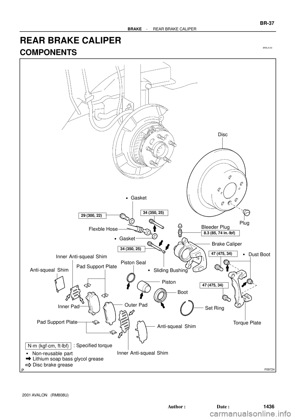
BR0LA-03
F09724
Brake Caliper
Torque Plate Piston Seal
Set Ring Piston� Dust Boot
Pad Support Plate� Sliding Bushing
Inner Pad
Anti-squeal Shim
N´m (kgf´cm, ft´lbf): Specified torque
� Non-reusable part
Lithium soap bass glycol grease
Disc brake grease
Bleeder Plug
29 (300, 22)
8.3 (85, 74 in.´lbf)
47 (475, 34)
Inner Anti-squeal Shim Anti-squeal Shim
Plug
47 (475, 34)
Boot
Pad Support Plate
Outer Pad
Inner Anti-squeal Shim
34 (350, 25)
34 (350, 25)
Flexble Hose
Disc
Gasket
�
Gasket
�
- BRAKEREAR BRAKE CALIPER
BR-37
1436 Author�: Date�:
2001 AVALON (RM808U)
REAR BRAKE CALIPER
COMPONENTS
Page 537 of 1897

INSPECTION
1. MEASURE PAD LINING THICKNESS (See page
BR-31)
Standard thickness: 10.0 mm (0.394 in.)
Minimum")
BR0LD-03
F09729
BR-40
- BRAKEREAR BRAKE CALIPER
1439 Author�: Date�:
2001 AVALON (RM808U)
INSPECTION
1. MEASURE PAD LINING THICKNESS (See page
BR-31)
Standard thickness: 10.0 mm (0.394 in.)
Minimum thickness: 1.0 mm (0.039 in.)
2. MEASURE DISC THICKNESS
(See step 2 on page BR-31)
Standard thickness: 12.0 mm (0.472 in.)
Minimum thickness: 10.5 mm (0.413 in.)
3. MEASURE DISC RUNOUT
(See step 3 on page BR-31)
Maximum disc runout: 0.15 mm (0.0059 in.)
If the disc's runout is at the maximum value or greater, check the
bearing play in the axial direction and check the axle hub runout
(See page SA-45). If the bearing play and axle hub runout are
not abnormal, adjusting the disc runout or grind it on a ºOn-Carº
brake lathe.
4. IF NECESSARY, ADJUST DISC RUNOUT
(a) Remove the 2 bolts and torque plate.
(b) Remove the hub nuts and the disc. Reinstall the disc 1/5
of a turn round from its original position on the hub. Install
and torque the hub nuts.
Torque: 103 N´m (1050 kgf´cm, 76 ft´lbf)
Remeasure the disc runout. Make a note of the runout
and the disc's position on the hub.
(c) Repeat (b) until the disc has been installed on the 3 re-
maining hub positions.
(d) If the minimum runout recorded in (b) and (c) is less than
0.15 mm (0.0059 in.), install the disc in that position.
(e) If the minimum runout recorded in (b) and (c) is greater
than 0.15 mm (0.0059 in.), replace the disc and repeat
step 3.
(f) Install the torque plate and torque the mounting bolts.
Torque: 47 N´m (475 kgf´cm, 34 ft´lbf)
Page 540 of 1897

REMOVAL
1. REMOVE REAR WHEEL
Remove the wheel and temporarily fasten the disc with hub
nuts.
Torque: 103 N´")
BR0LB-02
F09725
BR-38
- BRAKEREAR BRAKE CALIPER
1437 Author�: Date�:
2001 AVALON (RM808U)
REMOVAL
1. REMOVE REAR WHEEL
Remove the wheel and temporarily fasten the disc with hub
nuts.
Torque: 103 N´m (1,050 kgf´cm, 76 ft´lbf)
2. DISCONNECT FLEXIBLE HOSE
(a) Remove the union bolt and 2 gaskets from the caliper,
then disconnect the flexible hose from the caliper.
Torque: 29 N´m (300 kgf´cm, 22 ft´lbf)
HINT:
At the time of installation, insert the flexible hose lock securely
in the lock hole in the caliper.
(b) Use a container to catch the brake fluid as it drains out.
3. REMOVE CALIPER
(a) Remove the 2 installation bolts.
Torque: 34 N´m (350 kgf´cm, 25 ft´lbf)
NOTICE:
At the time of installation, insert the sliding pin with sliding
bushing into the bottom side.
(b) Remove the caliper from the torque plate.
4. REMOVE 2 BRAKE PADS WITH ANTI- SQUEAL
SHIMS
5. REMOVE 4 PAD SUPPORT PLATES
NOTICE:
There should be no oil or grease adhering to the friction
surfaces of the pads or disc.
Page 541 of 1897
BR0L8-03
F09721
Anti-squeal Shim
Inner Anti-squeal Shim
Outer Pad Pad Support Plate
Disc brake grease
N´m (kgf´cm, ft´lbf): Specified torque
Inner Anti-squeal Shim
Anti-squeal Shim
Pad Support PlateInner Pad
34 (350, 35)
BR-34
- BRAKEREAR BRAKE PAD
1433 Author�: Date�:
2001 AVALON (RM808U)
REAR BRAKE PAD
COMPONENTS


: Specified torque
Inner Anti-squeal Shim
Anti-squeal Shim
Pad Support Plat")