Page 563 of 1897
CH03Z-02
P14225
P00628
Socket Wrench
P00479
SST
N00581
SST
P13567
- CHARGINGGENERATOR
CH-1 1
1284 Author�: Date�:
2001 AVALON (RM808U)
REPLACEMENT
1. REPLACE FRONT BEARING
(a) Remove the 4 screws and bearing retainer.
(b) Using a socket wrench and press, press out the bearing.
(c) Using SST and a press, press in a new bearing.
SST 09950-60010 (09951-00520)
(d) Install the bearing retainer with the 4 screws.
Torque: 3.0 N´m (31 kgf´cm, 27 in.´lbf)
2. REPLACE REAR BEARING
(a) Using SST,remove the bearing cover (outside) and bear-
ing.
SST 09820-00021
NOTICE:
Be careful not to damage the fan.
(b) Remove the bearing cover (inside).
(c) Place the bearing cover (inside) on the rotor.
Page 569 of 1897

REPLACEMENT
1. DRAIN ENGINE COOLANT
(a) Remove the radiator cap from the water outlet.
CAUTION:
To")
CO02L-03
B09030Drain PlugDrain Plug
CO-2
- COOLINGCOOLANT
1195 Author�: Date�:
2001 AVALON (RM808U)
REPLACEMENT
1. DRAIN ENGINE COOLANT
(a) Remove the radiator cap from the water outlet.
CAUTION:
To avoid the danger of being burned, do not remove the ra-
diator cap while the engine and radiator are still hot, as fluid
and steam can be blown out under pressure.
(b) Loosen the radiator drain plug and engine drain plugs,
and drain the coolant.
(c) Close the drain plugs.
Torque:
RH engine drain plug on cylinder block side cover:
7 N´m (70 kgf´cm, 61 in.´lbf)
LH engine drain plug on union:
13 N´m (130 kgf´cm, 9 ft´lbf)
2. FILL ENGINE COOLANT
(a) Slowly fill the system with coolant.
�Use of improper coolants may damage engine cool-
ing system.
�Use ºToyota Long life Coolantº or equivalent and
mix it with plan water according to the manufactur-
er's directions.
�Using of coolant which includes more than 50 %
(freezing protection down to -35°C (-31°F) or 60 %
(freezing protection down to -50°C (-58°F)) of eth-
ylene-glycol is recommended but not more than 70
%.
NOTICE:
�Do not use an alcohol type coolant or plain water
alone.
�The coolant should be mixed with plain water (prefer-
ably demineralized water or distilled water).
Capacity: 9.0 liters (9.5 US qts, 7.9 lmp. qts)
(b) Install the radiator cap.
(c) Start the engine, and bleed the cooling system.
(d) If necessary, refill coolant into the reservoir up to the
ºFULLº line.
3. CHECK ENGINE COOLANT FOR LEAKS
4. CHECK ENGINE COOLANT SPECIFIC GRAVITY COR-
RECTLY
Page 575 of 1897
CO09O-02
B09051
No.1
B09052
No.2
- COOLINGELECTRIC COOLING FAN
CO-27
1220 Author�: Date�:
2001 AVALON (RM808U)
REMOVAL
REMOVE COOLING FANS
(a) Remove the No.1 cooling fan.
(1) Remove the batter and battery tray.
(2) Disconnect the cruise control actuator.
(3) Disconnect the No.3 engine room relay block from
radiator.
(4) Disconnect the cooling fan connector.
(5) Disconnect the wire clamps from the fan shroud.
(6) Remove the 2 bolts and cooling fan.
Torque: 5.0 N´m (50 kgf´cm, 44 in.´lbf)
(b) Remove the No.2 cooling fan.
(1) Drain the engine coolant.
(2) Disconnect the upper radiator hose from the radia-
tor.
(3) Disconnect the cooling fan and No.1 ECT switch
wire connectors.
(4) Disconnect the wire clamps from the fan shroud.
(5) Disconnect the No.1 ECT switch connector.
(6) Remove the 2 bolts and cooling fan.
Torque: 5.0 N´m (50 kgf´cm, 44 in.´lbf)
Page 584 of 1897
(2)
(3)(4) (5) (6)
CO1267
Lock Plate
Lock Plate
Core
CO0317
O-Ring� Normal
X Twisted
X Twisted
- COOLINGRADIATOR
CO-19
1212 Author�: Date�:
2001 AVALON (RM808U)
REASSEMBLY
1. INST")
CO02Z-03
S04435
(1)(2)
(3)(4) (5) (6)
CO1267
Lock Plate
Lock Plate
Core
CO0317
O-Ring� Normal
X Twisted
X Twisted
- COOLINGRADIATOR
CO-19
1212 Author�: Date�:
2001 AVALON (RM808U)
REASSEMBLY
1. INSTALL OIL COOLER TO LOWER TANK
(a) Clean the O-ring contact surface of the lower tank and oil
cooler.
(b) Install a new O-rings (1) to the oil cooler (2).
(c) Install the oil cooler with the O-rings to the lower tank (3).
(d) Install the plate washers (4), and nuts (5). Torque the
nuts.
Torque: 8.3 N´m (85 kgf´cm, 74 in.´lbf)
(e) Install the pipe (6).
Torque: 14.7 N´m (150 kgf´cm, 11 ft´lbf)
2. INSPECT LOCK PLATE
Inspect the lock plate for damage.
HINT:
�If the sides of the lock plate groove are deformed, reas-
sembly of the tank will be impossible.
�Therefore, first correct any deformation with pliers or simi-
lar object. Water leakage will result if the bottom of the
lock plate groove is damaged or dented, Therefore, repair
or replace if necessary.
NOTICE:
The radiator can only be recaulked 2 times. After the 2nd
time, the radiator core must be replaced.
3. INSTALL NEW O-RINGS AND TANKS
(a) After checking that there are no foreign objects in the lock
plate groove, install the new O-ring without twisting it.
HINT:
When cleaning the lock plate groove, lightly rub it with sand pa-
per without scratching it.
Page 587 of 1897

REMOVAL
HINT:
At the time of installation, please refer to the following items.
�Start the engine, and check for coo")
CO0WT-01
B09040
- COOLINGRADIATOR
CO-17
1210 Author�: Date�:
2001 AVALON (RM808U)
REMOVAL
HINT:
At the time of installation, please refer to the following items.
�Start the engine, and check for coolant and A/T fluid
leaks.
�Check the A/T fluid level (See page DI-160).
1. REMOVE BATTERY AND BATTERY TRAY
2. REMOVE ENGINE UNDER COVER
3. DRAIN ENGINE COOLANT
4. DISCONNECT NO.3 ENGINE ROOM RELAY BLOCK
FROM RADIATOR
5. DISCONNECT NO.1 COOLING FAN CONNECTOR
6. DISCONNECT WIRE CLAMPS FROM NO.1 FAN
SHROUD
7. DISCONNECT NO.2 COOLING FAN CONNECTOR
8. DISCONNECT NO.1 ECT SWITCH WIRE CONNECTOR
9. DISCONNECT WIRE CLAMPS FROM NO.2 FAN
SHROUD
10. DISCONNECT UPPER RADIATOR HOSE FROM RA-
DIATOR
11. DISCONNECT LOWER RADIATOR HOSE FROM RA-
DIATOR
12. DISCONNECT A/T OIL COOLER HOSES FROM RA-
DIATOR
13. REMOVE RADIATOR AND COOLING FANS AS-
SEMBLY
(a) Remove the 2 bolts and 2 upper supports.
Torque: 12.8 N´m (130 kgf´cm, 9 ft´lbf)
(b) Lift out the radiator, and remove the radiator and cooling
fans assembly.
(c) Remove the 2 lower supports.
14. REMOVE NO.1 ECT SWITCH
15. REMOVE NO.1 COOLING FAN FROM RADIATOR
Remove the 2 bolts and cooling fan.
Torque: 5.0 N´m (50 kgf´cm, 44 in.´lbf)
16. REMOVE NO.2 COOLING FAN FROM RADIATOR
Remove the 2 bolts and cooling fan.
Torque: 5.0 N´m (50 kgf´cm, 44 in.´lbf)
Page 588 of 1897
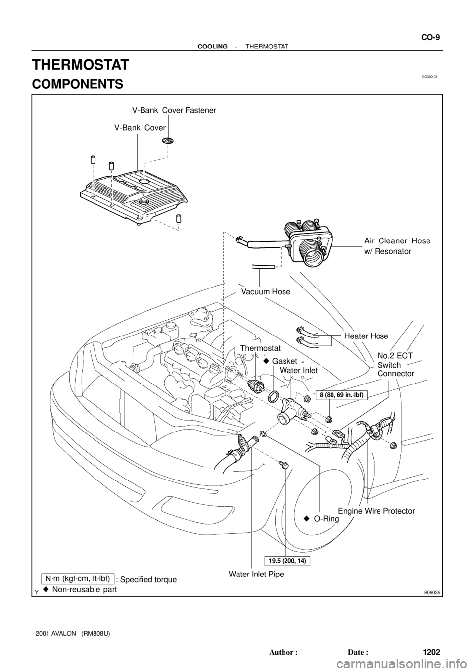
CO02Q-03
B09035
V-Bank Cover
Air Cleaner Hose
w/ Resonator
Engine Wire Protector
Thermostat
� Gasket
Water Inlet
Water Inlet PipeN´m (kgf´cm, ft´lbf)
: Specified torque
� O-Ring
No.2 ECT
Switch
Connector
8 (80, 69 in.´lbf)
19.5 (200, 14)
� Non-reusable part
Vacuum Hose
Heater Hose
V-Bank Cover Fastener
- COOLINGTHERMOSTAT
CO-9
1202 Author�: Date�:
2001 AVALON (RM808U)
THERMOSTAT
COMPONENTS
Page 590 of 1897

INSTALLATION
1. PLACE THERMOSTAT IN WATER PUMP
(a) Install a new gasket on to the th")
CO02T-03
B04153Stud BoltJiggle Valve
15°15°
CO-12
- COOLINGTHERMOSTAT
1205 Author�: Date�:
2001 AVALON (RM808U)
INSTALLATION
1. PLACE THERMOSTAT IN WATER PUMP
(a) Install a new gasket on to the thermostat.
(b) Align the thermostat jiggle valve with the upper stud bolt,
and insert the thermostat in the water inlet housing.
HINT:
The jiggle valve may be set within 15° of either side of the pre-
scribed position.
2. INSTALL WATER INLET
Install the water inlet with the 3 nuts.
Torque: 8 N´m (80 kgf´cm, 69 in.´lbf)
3. INSTALL WATER INLET PIPE
(a) Install a new O-ring to the water inlet pipe.
(b) Apply soapy water to the O-ring.
(c) Connect the water inlet pipe to the water inlet.
(d) Install the bolt holding the water inlet pipe to the LH cylin-
der head.
Torque: 19.5 N´m (200 kgf´cm, 14 ft´lbf)
4. INSTALL ENGINE WIRE PROTECTOR
5. CONNECT NO.2 ECT SWITCH CONNECTOR
6. CONNECT HEATER HOSES
7. REINSTALL AIR CLEANER HOSE WITH RESONATOR
8. INSTALL V-BANK COVER
(a) Using 5 mm hexagon wrench, install the V-bank cover
with the 3 cap nuts.
(b) Press down the V-bank cover fastener.
9. FILL WITH ENGINE COOLANT
10. START ENGINE AND CHECK FOR LEAKS
11. RECHECK ENGINE COOLANT LEVEL
Page 592 of 1897
CO02M-03
A10834
RH Fender Apron Seal
Generator Drive Belt
Engine Moving
Control Rod
No.2 RH Engine
Mounting Bracket
Ground Strap
Connector PS Pump Drive Belt
Engine Coolant Reservoir Hose
: Specified torque
64 (650, 47)
32 (320, 23)
N´m (kgf´cm, ft´lbf)
- COOLINGWATER PUMP
CO-3
1196 Author�: Date�:
2001 AVALON (RM808U)
WATER PUMP
COMPONENTS