Page 1318 of 1897
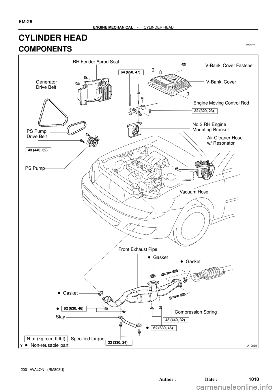
EM042-03
A10835
RH Fender Apron Seal
Generator
Drive Belt
No.2 RH Engine
Mounting Bracket
PS Pump
Drive Belt
PS Pump
� Non-reusable part: Specified torque
64 (650, 47)
32 (320, 23)
43 (440, 32)
N´m (kgf´cm, ft´lbf)
� Gasket
62 (630, 46)
43 (440, 32)
� Gasket
�
62 (630, 46)
33 (330, 24)
�Front Exhaust Pipe
Stay
� Gasket
Compression Spring
V-Bank Cover
Air Cleaner Hose
w/ Resonator
Vacuum Hose
Engine Moving Control Rod V-Bank Cover Fastener
EM-26
- ENGINE MECHANICALCYLINDER HEAD
1010 Author�: Date�:
2001 AVALON (RM808U)
CYLINDER HEAD
COMPONENTS
Page 1319 of 1897
Water Bypass Hose
A10522
PS Pressure Tube
Throttle Body Bracket
Engine WireThrottle Position
Sensor Connector
Vacuum Hose Brake Booster
39 (400,29)
IAC Valve
Connector
Accelerator Cable
Purge Hose
Hose Vacuum
�Gasket
VSV Connector for No.2 ACIS
Engine Coolant
Reservoir Hose
43 (440,32)
ECT Sender
Gauge Connector
ECT Sensor
Connector
Grand Strap
Connector
15 (150,11)
Water Outlet
15 (150,11)
Water Bypass
Hose
Upper Radiator
HoseFuel Inlet Hose
Injector Connector Intake Manifold
Assembly
�Retainer
Heater Hose
�GasketIgnition Coil
Connector
� Non-reusable part: Specified torque
N´m (kgf´cm, ft´lbf)
19.5 (200, 14)
No.1 Engine
Hanger
VSV Connector for
EVAP
Ground Cable
PCV Hose Ground Cable
Air Intake Chamber
Assembly
� Gasket
Spark PlugIgnition Coil
Ground Strap
DLC1
Gasket
Fuel Hose Clamp
VSV Connector
for No.1 ACIS
Throttle Cable
- ENGINE MECHANICALCYLINDER HEAD
EM-27
1011 Author�: Date�:
2001 AVALON (RM808U)
Page 1320 of 1897
A05070
Timing Belt
Gasket No.2 Timing Belt Cover
RH Engine Mounting Bracket
Crankshaft
Pulley No.1 Timing Belt Cover
Gasket
Engine Wire
Protector
No.2 Idler Pulley
RH Camshaft Timing Pulley
LH Camshaft
Timing Pulley
Timing Belt TensionerTiming Belt Guide
No.2 Generator
Bracket
Dust Boot
N´m (kgf´cm, ft´lbf) : Specified torque
* For use with SST� Non-reusable part
28 (290, 21)
215 (2,200, 159)
125 (1,300, 94)
*88 (900, 65)
27 (280, 20)
43 (440, 32)
125 (1,300, 94)
EM-28
- ENGINE MECHANICALCYLINDER HEAD
1012 Author�: Date�:
2001 AVALON (RM808U)
Page 1321 of 1897
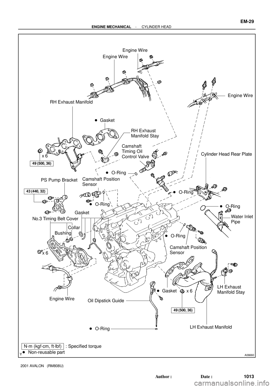
A06660
Engine Wire
Engine Wire
RH Exhaust Manifold
49 (500, 36)
x 6Cylinder Head Rear Plate
PS Pump Bracket
43 (440, 32)
Gasket
No.3 Timing Belt Cover
CollarWater Inlet
Pipe
x 6
� O-Ring Oil Dipstick Guide
N´m (kgf´cm, ft´lbf) : Specified torque
� Non-reusable part� Gasket
Engine Wire
Engine Wire
49 (500, 36)
Bushing
Camshaft Position
Sensor
LH Exhaust
Manifold Stay
x 6
� Gasket
� O-Ring
� O-Ring
LH Exhaust Manifold
� O-Ring
Camshaft
Timing Oil
Control Valve
Camshaft Position
SensorRH Exhaust
Manifold Stay
� O-Ring
� O-Ring
- ENGINE MECHANICALCYLINDER HEAD
EM-29
1013 Author�: Date�:
2001 AVALON (RM808U)
Page 1322 of 1897

A05703
Adjusting Shim
Valve Lifter
Keeper
Spring Retainer
Valve Spring
Spring Seat
� Oil Seal
Valve � Valve Guide BushingLH Cylinder Head Cover
LH Intake
Camshaft
Snap Ring Camshaft Sub-Gear
LH Exhaust
Camshaft RH Cylinder Head Cover
Gasket
RH Intake
Camshaft Camshaft Sub-Gear
Camshaft Gear Spring
RH Exhaust
CamshaftWave Washer
Semi-Circular PlugSemi-Circular
Plug
LH Cylinder Head
Camshaft
Bearing Cap
� Camshaft Oil Seal RH Cylinder Head
� RH Cylinder
Head Gasket
� LH Cylinder Head Gasket18 (185, 13)x 8
16 (160, 12)
See Page EM-59
1st 54 (550, 40)
2nd Turn 90°
N´m (kgf´cm, ft´lbf) : Specified torque
� Non-reusable part
� Spark Plug
Tube Gasket
Wave WasherGasketSnap RingCamshaft Gear Spring
Oil Control Valve Filter
� Gasket
Camshaft Timing
Gear (VVT-i)
� Gasket
� Gasket
Oil Control
Valve FilterCylinder Head
Rear CoverCylinder Head
Rear Cover� Gasket
150 (1,530, 110)
NOTICE:
Intake Camshaft
Do not remove or install the camshaft timing
gear (VVT-i) beside changing VVT-i or the
camshaft.
�
EM-30
- ENGINE MECHANICALCYLINDER HEAD
1014 Author�: Date�:
2001 AVALON (RM808U)
Page 1331 of 1897

17. INSPECT CAMSHAFT JOURNAL OIL CLEARANCE
(a) Clean the bearing caps and cams")
A05239
Plastigage
A05237
A05240
A05238
EM-48
- ENGINE MECHANICALCYLINDER HEAD
1032 Author�: Date�:
2001 AVALON (RM808U)
17. INSPECT CAMSHAFT JOURNAL OIL CLEARANCE
(a) Clean the bearing caps and camshaft journals.
(b) Place the camshafts on the cylinder head.
(c) Lay a strip of Plastigage across each of the camshaft jour-
nal.
(d) Install the bearing caps. (See page EM-59)
Torque: 16 N´m (160 kgf´cm, 12 ft´lbf)
NOTICE:
Do not turn the camshaft.
(e) Remove the bearing caps.
(f) Measure the Plastigage at its widest point.
Standard oil clearance:
Intake0.035 - 0.072 mm (0.0014 - 0.0028 in.)
Exhaust0.025 - 0.062 mm (0.0010 - 0.0024 in.)
Maximum oil clearance:
Intake0.10 mm (0.0039 in.)
Exhaust0.09 mm (0.0035 in.)
If the oil clearance is greater than maximum, replace the cam-
shaft. If necessary, replace the bearing caps and cylinder head
as a set.
(g) Completely remove the Plastigage.
(h) Remove the camshafts.
18. INSPECT CAMSHAFT THRUST CLEARANCE
(a) Install the camshafts. (See page EM-59)
(b) Using a dial indicator, measure the thrust clearance while
moving the camshaft back and forth.
Standard thrust clearance:
0.040 - 0.090 mm (0.0016 - 0.0035 in.)
Maximum thrust clearance: 0.12 mm (0.0047 in.)
If the thrust clearance is greater than maximum, replace the
camshaft. If necessary, replace the bearing caps and cylinder
head as a set.
Page 1335 of 1897

INSTALLATION
1. P")
EM0ZJ-02
A10520
A05218
12 Pointed Head Bolt
Front
7246
5318
7246
5318
A05223
Painted Mark
Front90°
- ENGINE MECHANICALCYLINDER HEAD
EM-59
1043 Author�: Date�:
2001 AVALON (RM808U)
INSTALLATION
1. PLACE CYLINDER HEAD ON CYLINDER BLOCK
(a) Place 2 new cylinder head gaskets in position on the cylin-
der block.
NOTICE:
Be careful of the installation direction.
(b) Place the 2 cylinder heads in position on the cylinder head
gaskets.
2. INSTALL 12 POINTED HEAD CYLINDER HEAD BOLTS
HINT:
�The cylinder head bolts are tightened in 2 progressive
steps (steps (c) and (e)).
�If any bolt is broken or deformed, replace it.
(a) Apply a light coat of engine oil on the threads and under
the heads of the cylinder head bolts.
(b) Install the plate washer to the cylinder head bolt.
(c) Install and uniformly tighten the cylinder head bolts on
each cylinder head in several passes and in the sequence
shown, then repeat for the other side, as shown.
Torque: 54 N´m (550 kgf´cm, 40 ft´lbf)
If any of the cylinder head bolts does not meet the torque speci-
fication, replace the cylinder head bolt.
(d) Mark the front of the cylinder head bolt head with paint.
(e) Retighten the cylinder head bolts by 90° in the numerical
order shown.
(f) Check that the painted mark is now at a 90° angle to the
front.
Page 1336 of 1897
A05221
Recessed Head Bolt
Front8 mm Hexagon Wrench
P12595
Z09320
(3)
(2)
(1)
P12590
EM-60
- ENGINE MECHANICALCYLINDER HEAD
1044 Author�: Date�:
2001 AVALON (RM808U)
3. INSTALL RECESSED HEAD CYLINDER HEAD BOLTS
(a) Apply a light coat of engine oil on the threads and under
the heads of the cylinder head bolts.
(b) Using an 8 mm hexagon wrench, install the cylinder head
bolt on each cylinder head, then repeat for the other side,
as shown.
Torque: 18.5 N´m (185 kgf´cm, 13 ft´lbf)
4. ASSEMBLE EXHAUST CAMSHAFTS
(a) Mount the hexagonal wrench head portion of the cam-
shaft in a vise.
NOTICE:
Be careful not to damage the camshaft.
(b) Install the camshaft gear spring (1) and camshaft sub-
gear (2).
HINT:
Attach the pins on the gears to the gear spring ends.
(c) Install the wave washer (3).
(d) Using snap ring pliers, install the snap ring.

IAC Valve
Connector
Accelerator Cable
Purge Hose
Hos")