Page 1396 of 1897
IG09Q-03
B07461
Camshaft Position
Sensor (Bank 2)V-Bank Cover
� O-Ring � O-Ring
� Non-reusable partCamshaft Position Sensor (Bank 1)
Camshaft Position Sensor
Connector
Camshaft Position Sensor
Connector
N´m (kgf´cm, ft´lbf) : Specified torque
8 (80, 69 in.´lbf)
Air Cleaner Hose
w/ Resonator
8 (80, 69 in.´lbf)
Vacuum Hose
IG-6
- IGNITIONCAMSHAFT POSITION SENSOR
1249 Author�: Date�:
2001 AVALON (RM808U)
CAMSHAFT POSITION SENSOR
COMPONENTS
Page 1397 of 1897

IG0DN-02
A10518
5 mm
Hexagon
Wrench
B06698
- IGNITIONCAMSHAFT POSITION SENSOR
IG-7
1250 Author�: Date�:
2001 AVALON (RM808U)
REPLACEMENT
1. REMOVE V-BANK COVER
(a) Using a 5 mm hexagon wrench, remove the 3 cap nuts.
(b) Loosen the V-bank cover fastener counterclockwise.
(c) Remove the V-bank cover.
2. REMOVE AIR CLEANER HOSE WITH RESONATOR
3. REMOVE CAMSHAFT POSITION SENSORS
(a) Disconnect the 2 camshaft position sensor connectors.
(b) Remove the bolt and camshaft position sensor. Remove
the 2 camshaft position sensors.
(c) Remove the O-rings from the camshaft position sensors.
4. REINSTALL NEW CAMSHAFT POSITION SENSORS
(a) Install new O-rings to new camshaft position sensors.
(b) Install the camshaft position sensor with the bolt. Install
the 2 camshaft position sensors.
Torque: 8 N´m (80 kgf´cm, 69 in.´lbf)
(c) Connect the 2 camshaft position sensor connectors.
5. REINSTALL AIR CLEANER HOSE WITH RESONATOR
6. REINSTALL V-BANK COVER
(a) Using 5 mm hexagon wrench, install the V-bank cover
with the 3 cap nuts.
(b) Press down the V-bank cover fastener.
Page 1398 of 1897
IG067-03
B07462
Crankshaft Position Sensor
Connector
Crankshaft Position
Sensor
RH Fender Apron Seal
8 (80, 69 in.´lbf)
N´m (kgf´cm, ft´lbf) : Specified torque
IG-8
- IGNITIONCRANKSHAFT POSITION SENSOR
1251 Author�: Date�:
2001 AVALON (RM808U)
CRANKSHAFT POSITION SENSOR
COMPONENTS
Page 1399 of 1897
IG068-02
B06520
- IGNITIONCRANKSHAFT POSITION SENSOR
IG-9
1252 Author�: Date�:
2001 AVALON (RM808U)
REPLACEMENT
1. REMOVE RH FENDER APRON SEAL
2. REMOVE CRANKSHAFT POSITION SENSOR
(a) Disconnect the crankshaft position sensor connector.
(b) Remove the bolt and crankshaft position sensor.
3. REINSTALL NEW CRANKSHAFT POSITION SENSOR
(a) Install a new crankshaft position sensor with the bolt.
Torque: 8 N´m (80 kgf´cm, 69 in.´lbf)
(b) Connect the crankshaft position sensor connector.
4. REINSTALL RH FENDER APRON SEAL
Page 1400 of 1897
IG09O-03
B07460
V-Bank Cover
Ignition Coil
(w/ Igniter) Ignition Coil
Connector
Gasket
8 (80, 69 in.´lbf)
N´m (kgf´cm, ft´lbf) : Specified torque
IG-4
- IGNITIONIGNITION COIL
1247 Author�: Date�:
2001 AVALON (RM808U)
IGNITION COIL
COMPONENTS
Page 1401 of 1897
IG0DM-02
A10518
5 mm
Hexagon
Wrench
B06515
- IGNITIONIGNITION COIL
IG-5
1248 Author�: Date�:
2001 AVALON (RM808U)
REPLACEMENT
1. REMOVE V-BANK COVER
(a) Using a 5 mm hexagon wrench, remove the 3 cap nuts.
(b) Loosen the V-bank cover fastener counterclockwise.
(c) Remove the V-bank cover.
2. REMOVE IGNITION COILS
(a) Disconnect the 6 ignition coil connectors.
(b) Remove the bolt, and pull out the ignition coil. Remove
the 6 ignition coils.
3. REINSTALL NEW IGNITION COILS
(a) Connect a new ignition coil to the spark plug, and attach
the ignition coil to the cylinder head cover, and install the
bolt. Install the 6 ignition coils.
Torque: 8 N´m (80 kgf´cm, 69 in.´lbf)
(b) Connect the 6 ignition coil connectors.
4. REINSTALL V-BANK COVER
(a) Using 5 mm hexagon wrench, install the V-bank cover
with the 3 cap nuts.
(b) Press down the V-bank cover fastener.
Page 1405 of 1897

IG0152
B06521
Ohmmeter
P14244
Ohmmeter
- IGNITIONIGNITION SYSTEM
IG-3
1246 Author�: Date�:
2001 AVALON (RM808U)
(f) Clean the spark plugs.
If the electrode has traces of wet carbon, allow it to dry and then
clean with a spark plug cleaner.
Air pressure: Below 588 kPa (6 kgf/cm
2, 85 psi)
Duration: 20 seconds or less
HINT:
If there are traces of oil, remove it with gasoline before using the
spark plug cleaner.
(g) Using a 16 mm plug wrench, install the 6 spark plugs.
Torque: 18 N´m (180 kgf´cm, 13 ft´lbf)
(h) Reinstall the 6 ignition coil (See page IG-5).
3. INSPECT IGNITION COILS (WITH IGNITERS)
(See step 1.)
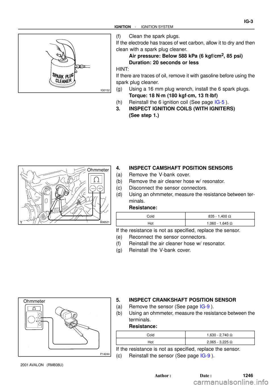
4. INSPECT CAMSHAFT POSITION SENSORS
(a) Remove the V-bank cover.
(b) Remove the air cleaner hose w/ resonator.
(c) Disconnect the sensor connectors.
(d) Using an ohmmeter, measure the resistance between ter-
minals.
Resistance:
Cold835 - 1,400 W
Hot1,060 - 1,645 W
If the resistance is not as specified, replace the sensor.
(e) Reconnect the sensor connectors.
(f) Reinstall the air cleaner hose w/ resonator.
(g) Reinstall the V-bank cover.
5. INSPECT CRANKSHAFT POSITION SENSOR
(a) Remove the sensor (See page IG-9).
(b) Using an ohmmeter, measure the resistance between the
terminals.
Resistance:
Cold1,630 - 2,740 W
Hot2,065 - 3,225 W
If the resistance is not as specified, replace the sensor.
(c) Reinstall the sensor (See page IG-9).
Page 1431 of 1897

IN00U-36
N17080
Filler Cap
Float
Reservoir
� Grommet
Clip
Slotted Spring Pin
: Specified torque
� Non-reusable partCylinder
Piston
Push Rod
Washer
Snap Ring
Boot
� Gasket
Lock Nut
Clevis Pin
Clevis
N´m (kgf´cm, ft´lbf)
12 (120, 9)
15 (155, 11)
- INTRODUCTIONHOW TO USE THIS MANUAL
IN-1
1 Author�: Date�:
2001 AVALON (RM808U)
HOW TO USE THIS MANUAL
GENERAL INFORMATION
1. INDEX
An INDEX is provided on the first page of each section to guide you to the item to be repaired. To assist you
in finding your way through the manual, the section title and major heading are given at the top of every page.
2. PRECAUTION
At the beginning of each section, a PRECAUTION is given that pertains to all repair operations contained
in that section.
Read these precautions before starting any repair task.
3. TROUBLESHOOTING
TROUBLESHOOTING tables are included for each system to help you diagnose the problem and find the
cause. The fundamentals of how to proceed with troubleshooting are described on page IN-20.
Be sure to read this before performing troubleshooting.
4. PREPARATION
Preparation lists the SST (Special Service Tools), recommended tools, equipment, lubricant and SSM (Spe-
cial Service Materials) which should be prepared before beginning the operation and explains the purpose
of each one.
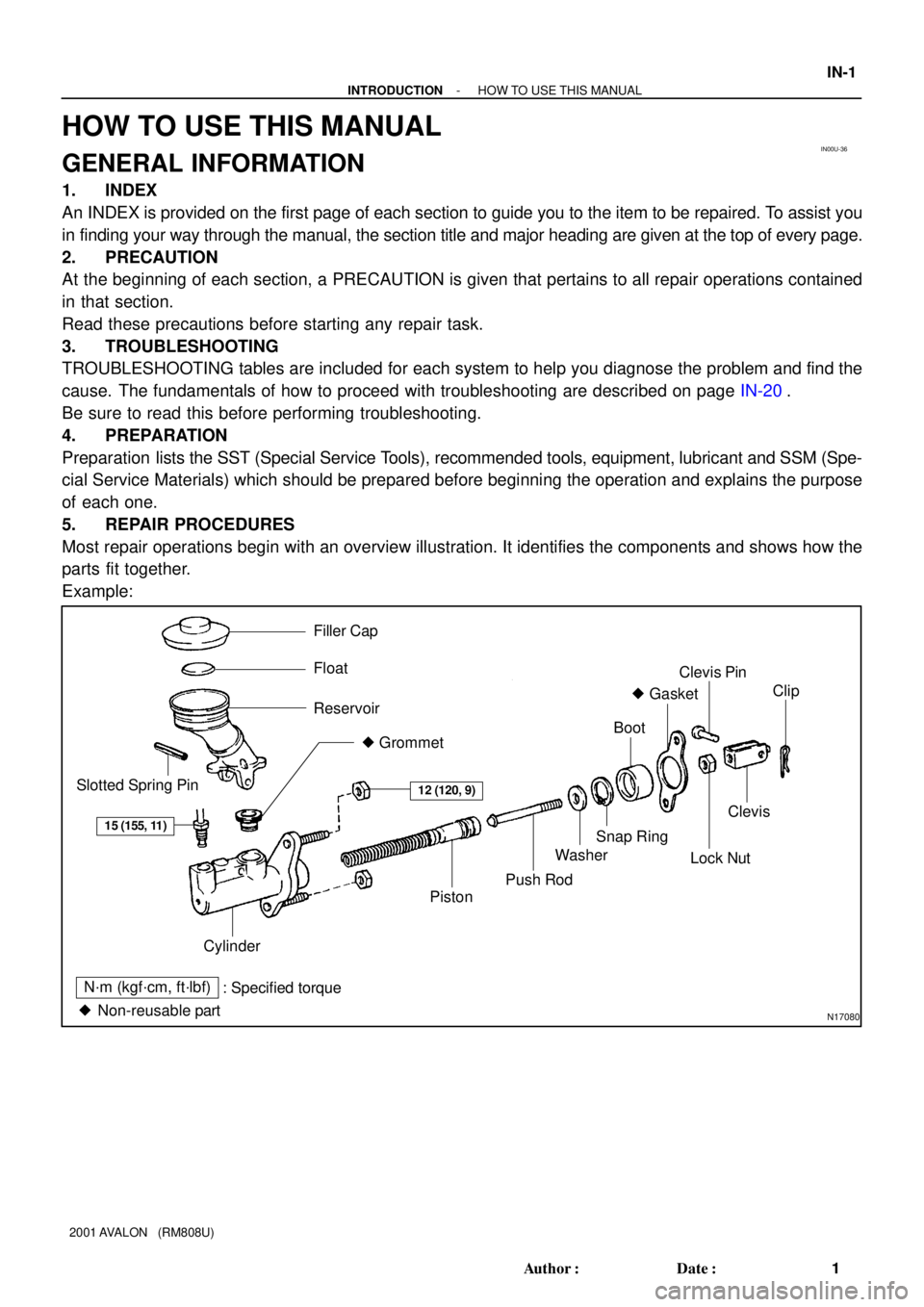
5. REPAIR PROCEDURES
Most repair operations begin with an overview illustration. It identifies the components and shows how the
parts fit together.
Example: