Page 1338 of 1897
A05283
Exhaust
A05202
Exhaust
7
A05203
Intake
Align
A05204
Intake
A05196
Intake
8
7
6
5
4
32
1
9
10
EM-62
- ENGINE MECHANICALCYLINDER HEAD
1046 Author�: Date�:
2001 AVALON (RM808U)
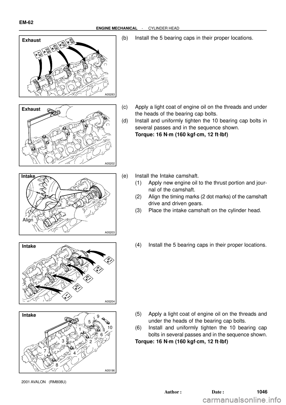
(b) Install the 5 bearing caps in their proper locations.
(c) Apply a light coat of engine oil on the threads and under
the heads of the bearing cap bolts.
(d) Install and uniformly tighten the 10 bearing cap bolts in
several passes and in the sequence shown.
Torque: 16 N´m (160 kgf´cm, 12 ft´lbf)
(e) Install the Intake camshaft.
(1) Apply new engine oil to the thrust portion and jour-
nal of the camshaft.
(2) Align the timing marks (2 dot marks) of the camshaft
drive and driven gears.
(3) Place the intake camshaft on the cylinder head.
(4) Install the 5 bearing caps in their proper locations.
(5) Apply a light coat of engine oil on the threads and
under the heads of the bearing cap bolts.
(6) Install and uniformly tighten the 10 bearing cap
bolts in several passes and in the sequence shown.
Torque: 16 N´m (160 kgf´cm, 12 ft´lbf)
Page 1340 of 1897
A05210
Exhaust
8
7
6
5
4
32
1
9
10
A05211
Intake
Align
A05214
Intake
A05213
Intake6
5
4
3
2
1
910
7
8
A05198
IntakeService Bolt
EM-64
- ENGINE MECHANICALCYLINDER HEAD
1048 Author�: Date�:
2001 AVALON (RM808U)
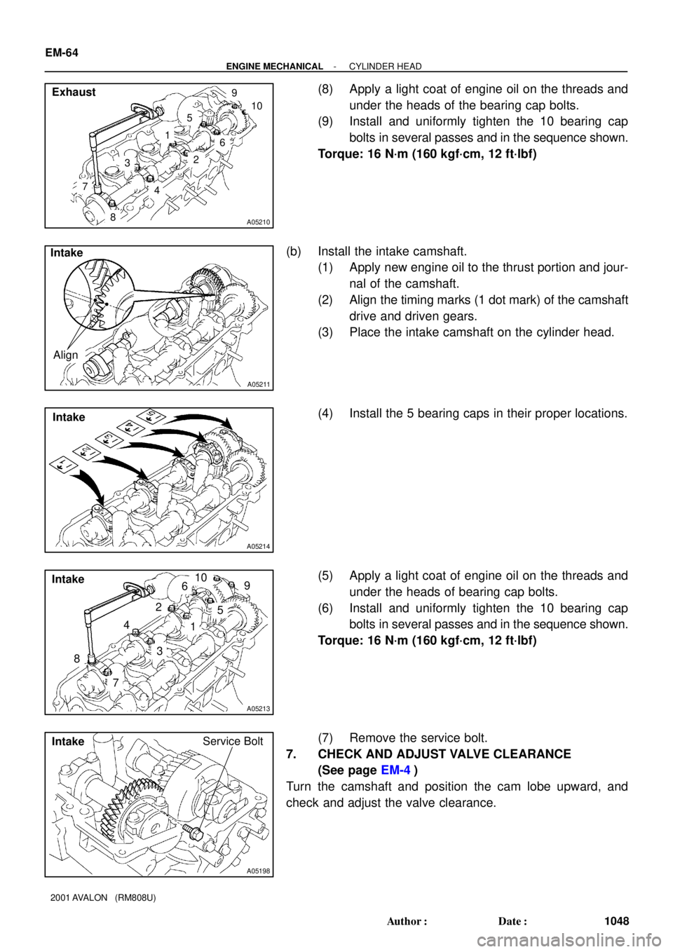
(8) Apply a light coat of engine oil on the threads and
under the heads of the bearing cap bolts.
(9) Install and uniformly tighten the 10 bearing cap
bolts in several passes and in the sequence shown.
Torque: 16 N´m (160 kgf´cm, 12 ft´lbf)
(b) Install the intake camshaft.
(1) Apply new engine oil to the thrust portion and jour-
nal of the camshaft.
(2) Align the timing marks (1 dot mark) of the camshaft
drive and driven gears.
(3) Place the intake camshaft on the cylinder head.
(4) Install the 5 bearing caps in their proper locations.
(5) Apply a light coat of engine oil on the threads and
under the heads of bearing cap bolts.
(6) Install and uniformly tighten the 10 bearing cap
bolts in several passes and in the sequence shown.
Torque: 16 N´m (160 kgf´cm, 12 ft´lbf)
(7) Remove the service bolt.
7. CHECK AND ADJUST VALVE CLEARANCE
(See page EM-4)
Turn the camshaft and position the cam lobe upward, and
check and adjust the valve clearance.
Page 1341 of 1897
A05215
Seal Packing
A05217
FrontSemi-Circular Plug
A05216
: Seal Packing
Front
RH Side
LH Side
- ENGINE MECHANICALCYLINDER HEAD
EM-65
1049 Author�: Date�:
2001 AVALON (RM808U)
8. INSTALL SEMI-CIRCULAR PLUGS
(a) Remove any old packing (FIPG) material.
(b) Apply seal packing to the semi-circular plug grooves.
Seal packing: Part No. 08826-00080 or equivalent
(c) Install the 2 semi-circular plugs to the cylinder heads.
9. INSTALL CYLINDER HEAD COVERS
(a) Apply seal packing to the cylinder heads as shown in the
illustration.
Seal packing: Part No. 08826-00080 or equivalent
(b) Install the gasket to the cylinder head cover.
(c) Install the cylinder head cover with the 9 bolts. Uniformly
tighten the bolts in several passes. Install the 2 cylinder
head covers.
Torque: 8 N´m (80 kgf´cm, 69 in.´lbf)
10. INSTALL PS PUMP BRACKET
Torque: 43 N´m (440 kgf´cm, 32 ft´lbf)
Page 1342 of 1897
A06661
Manifold
Stay
A07283
New O-Ring
A07281
Manifold
Stay
A05188Inlet PipeRear
Plate
EM-66
- ENGINE MECHANICALCYLINDER HEAD
1050 Author�: Date�:
2001 AVALON (RM808U)
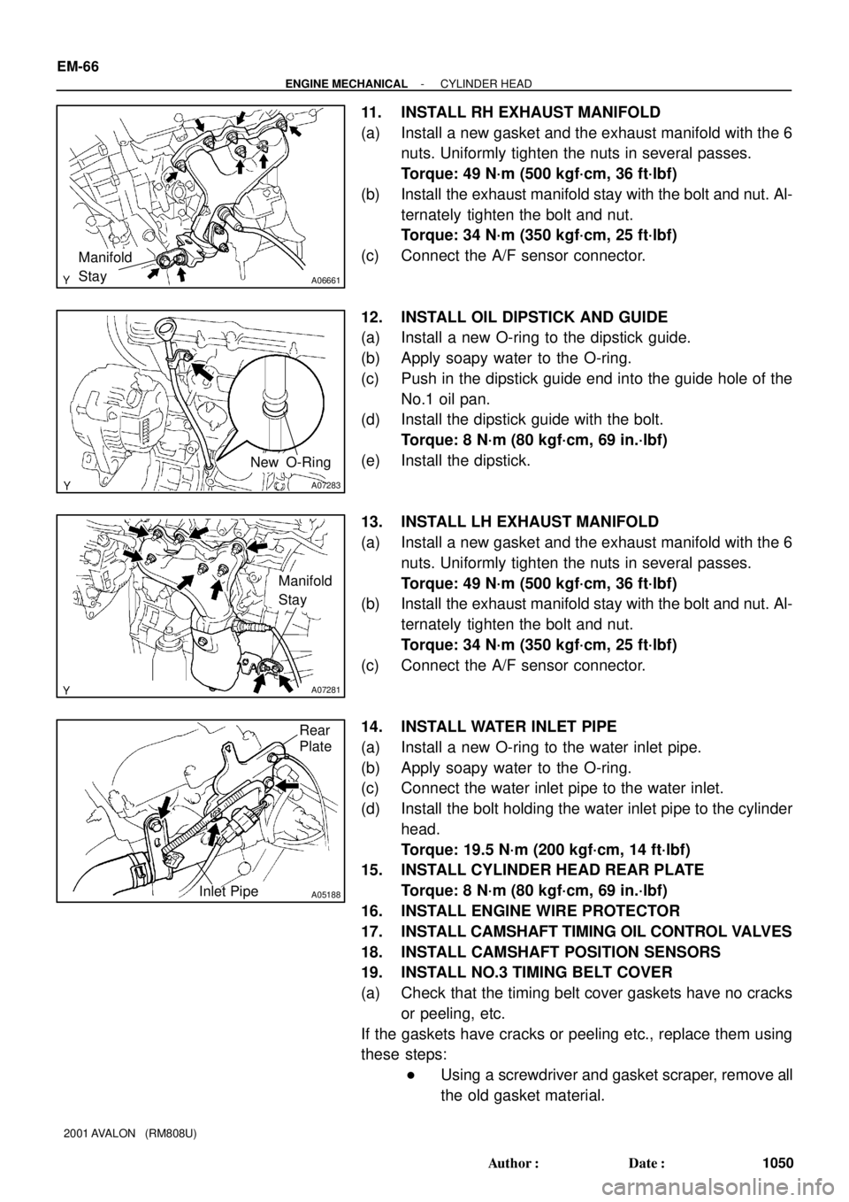
11. INSTALL RH EXHAUST MANIFOLD
(a) Install a new gasket and the exhaust manifold with the 6
nuts. Uniformly tighten the nuts in several passes.
Torque: 49 N´m (500 kgf´cm, 36 ft´lbf)
(b) Install the exhaust manifold stay with the bolt and nut. Al-
ternately tighten the bolt and nut.
Torque: 34 N´m (350 kgf´cm, 25 ft´lbf)
(c) Connect the A/F sensor connector.
12. INSTALL OIL DIPSTICK AND GUIDE
(a) Install a new O-ring to the dipstick guide.
(b) Apply soapy water to the O-ring.
(c) Push in the dipstick guide end into the guide hole of the
No.1 oil pan.
(d) Install the dipstick guide with the bolt.
Torque: 8 N´m (80 kgf´cm, 69 in.´lbf)
(e) Install the dipstick.
13. INSTALL LH EXHAUST MANIFOLD
(a) Install a new gasket and the exhaust manifold with the 6
nuts. Uniformly tighten the nuts in several passes.
Torque: 49 N´m (500 kgf´cm, 36 ft´lbf)
(b) Install the exhaust manifold stay with the bolt and nut. Al-
ternately tighten the bolt and nut.
Torque: 34 N´m (350 kgf´cm, 25 ft´lbf)
(c) Connect the A/F sensor connector.
14. INSTALL WATER INLET PIPE
(a) Install a new O-ring to the water inlet pipe.
(b) Apply soapy water to the O-ring.
(c) Connect the water inlet pipe to the water inlet.
(d) Install the bolt holding the water inlet pipe to the cylinder
head.
Torque: 19.5 N´m (200 kgf´cm, 14 ft´lbf)
15. INSTALL CYLINDER HEAD REAR PLATE
Torque: 8 N´m (80 kgf´cm, 69 in.´lbf)
16. INSTALL ENGINE WIRE PROTECTOR
17. INSTALL CAMSHAFT TIMING OIL CONTROL VALVES
18. INSTALL CAMSHAFT POSITION SENSORS
19. INSTALL NO.3 TIMING BELT COVER
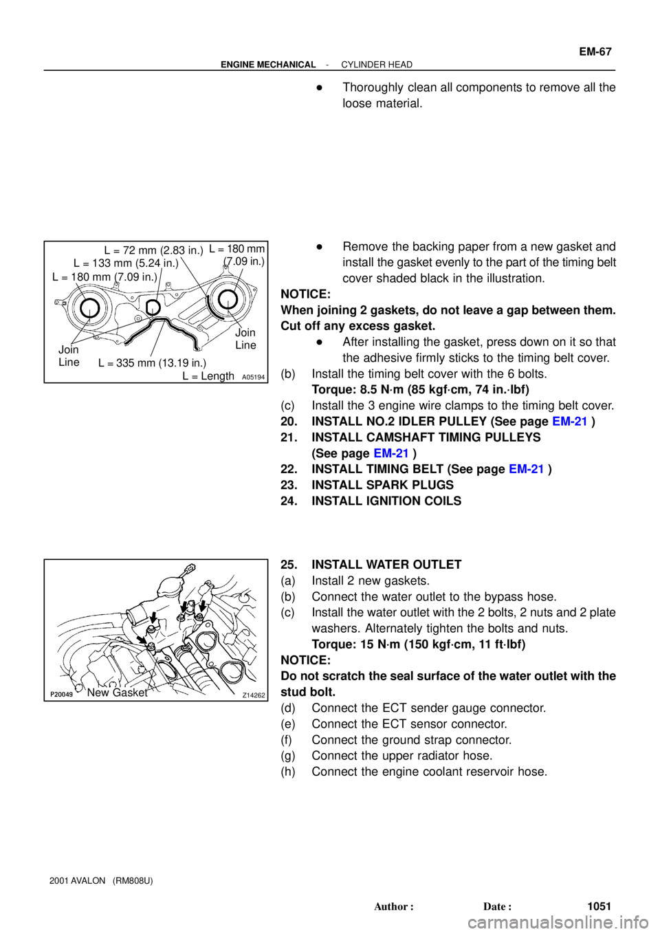
(a) Check that the timing belt cover gaskets have no cracks
or peeling, etc.
If the gaskets have cracks or peeling etc., replace them using
these steps:
�Using a screwdriver and gasket scraper, remove all
the old gasket material.
Page 1343 of 1897
A05194
L = 133 mm (5.24 in.)
L = 180 mm (7.09 in.)L = 72 mm (2.83 in.)
L = 335 mm (13.19 in.)L = 180 mm
(7.09 in.)
L = Length Join
LineJoin
Line
Z14262New Gasket
- ENGINE MECHANICALCYLINDER HEAD
EM-67
1051 Author�: Date�:
2001 AVALON (RM808U)
�Thoroughly clean all components to remove all the
loose material.
�Remove the backing paper from a new gasket and
install the gasket evenly to the part of the timing belt
cover shaded black in the illustration.
NOTICE:
When joining 2 gaskets, do not leave a gap between them.
Cut off any excess gasket.
�After installing the gasket, press down on it so that
the adhesive firmly sticks to the timing belt cover.
(b) Install the timing belt cover with the 6 bolts.
Torque: 8.5 N´m (85 kgf´cm, 74 in.´lbf)
(c) Install the 3 engine wire clamps to the timing belt cover.
20. INSTALL NO.2 IDLER PULLEY (See page EM-21)
21. INSTALL CAMSHAFT TIMING PULLEYS
(See page EM-21)
22. INSTALL TIMING BELT (See page EM-21)
23. INSTALL SPARK PLUGS
24. INSTALL IGNITION COILS
25. INSTALL WATER OUTLET
(a) Install 2 new gaskets.
(b) Connect the water outlet to the bypass hose.
(c) Install the water outlet with the 2 bolts, 2 nuts and 2 plate
washers. Alternately tighten the bolts and nuts.
Torque: 15 N´m (150 kgf´cm, 11 ft´lbf)
NOTICE:
Do not scratch the seal surface of the water outlet with the
stud bolt.
(d) Connect the ECT sender gauge connector.
(e) Connect the ECT sensor connector.
(f) Connect the ground strap connector.
(g) Connect the upper radiator hose.
(h) Connect the engine coolant reservoir hose.
Page 1344 of 1897
A07428
86
5 43 2
1
910
7
117
A09699
8 mm Hexagon Wrench
A09695
Throttle Body
Bracket
Engine
Hanger
EM-68
- ENGINE MECHANICALCYLINDER HEAD
1052 Author�: Date�:
2001 AVALON (RM808U)
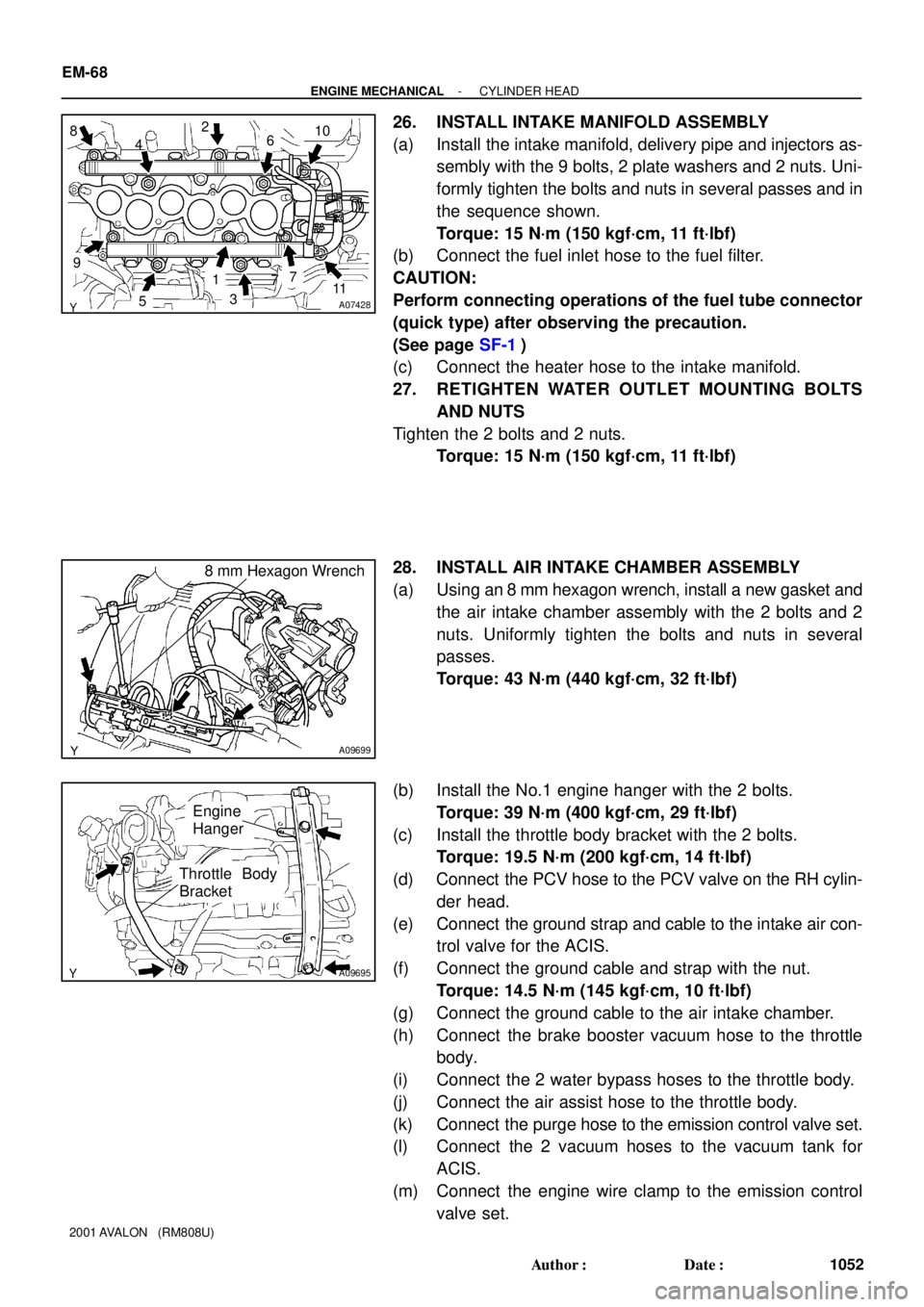
26. INSTALL INTAKE MANIFOLD ASSEMBLY
(a) Install the intake manifold, delivery pipe and injectors as-
sembly with the 9 bolts, 2 plate washers and 2 nuts. Uni-
formly tighten the bolts and nuts in several passes and in
the sequence shown.
Torque: 15 N´m (150 kgf´cm, 11 ft´lbf)
(b) Connect the fuel inlet hose to the fuel filter.
CAUTION:
Perform connecting operations of the fuel tube connector
(quick type) after observing the precaution.
(See page SF-1)
(c) Connect the heater hose to the intake manifold.
27. RETIGHTEN WATER OUTLET MOUNTING BOLTS
AND NUTS
Tighten the 2 bolts and 2 nuts.
Torque: 15 N´m (150 kgf´cm, 11 ft´lbf)
28. INSTALL AIR INTAKE CHAMBER ASSEMBLY
(a) Using an 8 mm hexagon wrench, install a new gasket and
the air intake chamber assembly with the 2 bolts and 2
nuts. Uniformly tighten the bolts and nuts in several
passes.
Torque: 43 N´m (440 kgf´cm, 32 ft´lbf)
(b) Install the No.1 engine hanger with the 2 bolts.
Torque: 39 N´m (400 kgf´cm, 29 ft´lbf)
(c) Install the throttle body bracket with the 2 bolts.
Torque: 19.5 N´m (200 kgf´cm, 14 ft´lbf)
(d) Connect the PCV hose to the PCV valve on the RH cylin-
der head.
(e) Connect the ground strap and cable to the intake air con-
trol valve for the ACIS.
(f) Connect the ground cable and strap with the nut.
Torque: 14.5 N´m (145 kgf´cm, 10 ft´lbf)
(g) Connect the ground cable to the air intake chamber.
(h) Connect the brake booster vacuum hose to the throttle
body.
(i) Connect the 2 water bypass hoses to the throttle body.
(j) Connect the air assist hose to the throttle body.
(k) Connect the purge hose to the emission control valve set.
(l) Connect the 2 vacuum hoses to the vacuum tank for
ACIS.
(m) Connect the engine wire clamp to the emission control
valve set.
Page 1346 of 1897

EM0ZI-02
P1151110 - 15 mm (0.39 - 0.59 in.)Adhesive
P12572
Protrusion
P12869
Flush
A05418
EM-56
- ENGINE MECHANICALCYLINDER HEAD
1040 Author�: Date�:
2001 AVALON (RM808U)
REASSEMBLY
HINT:
�Thoroughly clean all parts to be assembled.
�Before installing the parts, apply new engine oil to all slid-
ing and rotating surfaces.
�Replace all gaskets and oil seals with new ones.
1. INSTALL SPARK PLUG TUBES
HINT:
When using a new cylinder head, spark plug tubes must be
installed.
(a) Apply adhesive to the end of the spark plug tube.
Adhesive: Part No. 08833-00070, THREE BOND 1324
or equivalent
(b) Using a press, press in a new spark plug tube until there
is 42.4 - 43.4 mm (1.669 - 1.709 in.) protruding from the
camshaft bearing cap installation surface of the cylinder
head.
NOTICE:
Avoid pressing a new spark plug tube in too far by measur-
ing the amount of the protrusion while pressing.
2. INSTALL PCV PIPES
HINT:
When using a new cylinder head, PCV pipe must be installed.
Using a wooden block and hammer, tap in a new PCV pipe until
its top side is flush with the cylinder head edge.
NOTICE:
Be careful not to damage the cylinder head edge.
3. INSTALL OIL CONTROL VALVE FILTER
(a) Assemble the valve filter and plug.
(b) Install the plug with new gasket.
Torque: 45 N´m (460 kgf´cm, 33 ft´lbf)
Page 1347 of 1897
A05276
P12719
SST
Z19062
Intake ExhaustMark
ºNOKº or
ºFN , INº
Light Brown SurfaceGray Surface
P12668
(4)
(3)
(2)
(1)
A05224
SST
- ENGINE MECHANICALCYLINDER HEAD
EM-57
1041 Author�: Date�:
2001 AVALON (RM808U)
4. INSTALL CYLINDER HEAD REAR COVER
Install the rear cover and gasket with the 6 bolts.
Torque: 10 N´m (100 kgf´cm, 7.3 ft´lbf)
5. INSTALL VALVES
(a) Using SST, push in a new oil seal.
SST 09201-41020
HINT:
The intake valve oil seal is light brown and the exhaust valve oil
seal is gray.
NOTICE:
Pay much attention when assembling the oil seal for intake
and exhaust. Assembling the wrong one may cause a fail-
ure.
(b) Install the valve (1), spring seat (2), valve spring (3) and
spring retainer (4).
(c) Using SST, compress the valve spring and place the 2
keepers around the valve stem.
SST 09202-70020 (09202-00010)