Page 1432 of 1897

Task heading : what to do
SST 09350-30020 (09350-06120)
Set part No. Component part No.
Detailed text : how to do ta")
Illustration:
what to do and where
21. CHECK PISTON STROKE OF OVERDRIVE BRAKE
(a)
Task heading : what to do
SST 09350-30020 (09350-06120)
Set part No. Component part No.
Detailed text : how to do task
(b)
Piston stroke: 1.40 � 1.70 mm (0.0551 � 0.0669 in.)
Specification
Place SST and a dial indicator onto the overdrive brake pis-
ton as shown in the illustration.
Measure the stroke applying and releasing the compressed
air (392 � 785 kPa, 4 � 8 kgf/cm
2 or 57 � 114 psi) as shown
in the illustration. IN-2
- INTRODUCTIONHOW TO USE THIS MANUAL
2 Author�: Date�:
2001 AVALON (RM808U)
The procedures are presented in a step-by-step format:
�The illustration shows what to do and where to do it.
�The task heading tells what to do.
�The detailed text tells how to perform the task and gives other information such as specifications
and warnings.
Example:
This format provides the experienced technician with a FAST TRACK to the information needed. The upper
case task heading can be read at a glance when necessary, and the text below it provides detailed informa-
tion. Important specifications and warnings always stand out in bold type.
6. REFERENCES
References have been kept to a minimum. However, when they are required you are given the page to refer
to.
7. SPECIFICATIONS
Specifications are presented in bold type throughout the text where needed. You never have to leave the
procedure to look up your specifications. They are also found in Service Specifications section for quick ref-
erence.
8. CAUTIONS, NOTICES, HINTS:
�CAUTIONS are presented in bold type, and indicate there is a possibility of injury to you or other
people.
�NOTICES are also presented in bold type, and indicate the possibility of damage to the components
being repaired.
�HINTS are separated from the text but do not appear in bold. They provide additional information to
help you perform the repair efficiently.
9. SI UNIT
The UNITS given in this manual are primarily expressed according to the SI UNIT (International System of
Unit), and alternately expressed in the metric system and in the English System.
Example:
Torque: 30 N´m (310 kgf´cm, 22 ft´lbf)
Page 1435 of 1897
BE1367
Medium Current Fuse and High Current Fuse
Equal Amperage Rating
V00076
Abbreviation Part Name Symbol Illustration
FUSE
MEDIUM CURRENT FUSE
HIGH CURRENT FUSE
FUSIBLE LINK
CIRCUIT BREAKERFUSE
M-FUSE
H-FUSE
FL
CB
- INTRODUCTIONREPAIR INSTRUCTIONS
IN-5
5 Author�: Date�:
2001 AVALON (RM808U)
(3) Precoated parts are indicated in the component il-
lustrations by the º�º symbol.
(g) When necessary, use a sealer on gaskets to prevent
leaks.
(h) Carefully observe all specifications for bolt tightening
torques. Always use a torque wrench.
(i) Use of special service tools (SST) and special service ma-
terials (SSM) may be required, depending on the nature
of the repair. Be sure to use SST and SSM where speci-
fied and follow the proper work procedure. A list of SST
and SSM can be found in Preparation section in this
manual.
(j) When replacing fuses, be sure the new fuse has the cor-
rect amperage rating. DO NOT exceed the rating or use
one with a lower rating.
Page 1446 of 1897
 HO2S
Heated Oxygen SensorHeated Oxygen Sensor (HO2S)
IACIdle Air ControlIdle Speed Control (ISC)
IATIntake Air TemperatureIntake or")
- INTRODUCTIONTERMS
IN-41
41 Author�: Date�:
2001 AVALON (RM808U) HO2S
Heated Oxygen SensorHeated Oxygen Sensor (HO2S)
IACIdle Air ControlIdle Speed Control (ISC)
IATIntake Air TemperatureIntake or Inlet Air Temperature
ICMIgnition Control Module-
IFIIndirect Fuel InjectionIndirect Injection (IDL)
IFSInertia Fuel-Shutoff-
ISCIdle Speed Control-
KSKnock SensorKnock Sensor
MAFMass Air FlowAir Flow Meter
MAPManifold Absolute PressureManifold Pressure
Intake Vacuum
MCMixture Control
Electric Bleed Air Control Valve (EBCV)
Mixture Control Valve (MCV)
Electric Air Control Valve (EACV)
MDPManifold Differential Pressure-
MFIMultiport Fuel InjectionElectronic Fuel Injection (EFI)
MILMalfunction Indicator LampCheck Engine Lamp
MSTManifold Surface Temperature-
MVZManifold Vacuum Zone-
NVRAMNon-V olatile Random Access Memory-
O2SOxygen SensorOxygen Sensor, O2 Sensor (O2S)
OBDOn-Board DiagnosticOn-Board Diagnostic System (OBD)
OCOxidation Catalytic ConverterOxidation Catalyst Convert (OC), CCo
OPOpen LoopOpen Loop
PAIRPulsed Secondary Air InjectionAir Suction (AS)
PCMPowertrain Control Module-
PNPPark/Neutral Position-
PROMProgrammable Read Only Memory-
PSPPower Steering Pressure-
PTOXPeriodic Trap OxidizerDiesel Particulate Filter (DPF)
Diesel Particulate Trap (DPT)
RAMRandom Access MemoryRandom Access Memory (RAM)
RMRelay Module-
ROMRead Only MemoryRead Only Memory (ROM)
RPMEngine SpeedEngine Speed
SCSuperchargerSupercharger
SCBSupercharger BypassE-ABV
SFISequential Multiport Fuel InjectionElectronic Fuel Injection (EFI), Sequential Injection
SPLSmoke Puff Limiter-
SRIService Reminder Indicator-
SRTSystem Readiness Test-
STScan Tool-
TBThrottle BodyThrottle Body
TBIThrottle Body Fuel InjectionSingle Point Injection
Central Fuel Injection (Ci)
TCTurbochargerTurbocharger
TCCTorque Converter ClutchTorque Converter
Page 1449 of 1897
P12478
Adhesive
LU-2
- LUBRICATIONOIL AND FILTER
1227 Author�: Date�:
2001 AVALON (RM808U)
6. REMOVE OIL PRESSURE GAUGE AND REINSTALL
OIL PRESSURE SWITCH
(a) Remove the oil pressure gauge.
(b) Apply adhesive to 2 or 3 threads of the oil pressure switch.
Adhesive: Part No. 08833-00080, THREE BOND 1344,
LOCTITE 242 or equivalent
(c) Using SST, install the oil pressure switch.
SST 09816-30010
Torque: 13 N´m (130 kgf´cm, 9 ft´lbf)
7. START ENGINE AND CHECK FOR LEAKS
Page 1451 of 1897
LU-4
- LUBRICATIONOIL AND FILTER
1229 Author�: Date�:
2001 AVALON (RM808U)
3. REFILL WITH ENGINE OIL
(a) Clean and install the oil drain plug with a new gasket.
Torque: 45 N´m (460 kgf´cm, 33 ft´lbf)
(b) Fill with fresh engine oil.
Capacity:
Drain and refill w/ Oilfilter change
w/o Oilfilter change4.7 liters (5.0 US qts, 4.1 lmp. qts)
4.5 liters (4.8 US qts, 4.0 lmp. qts)
Dry fill5.2 liters (5.5 US qts, 4.6 lmp. qts)
(c) Install the oil filler cap.
4. START ENGINE AND CHECK FOR OIL LEAKS
5. RECHECK ENGINE OIL LEVEL
Page 1452 of 1897
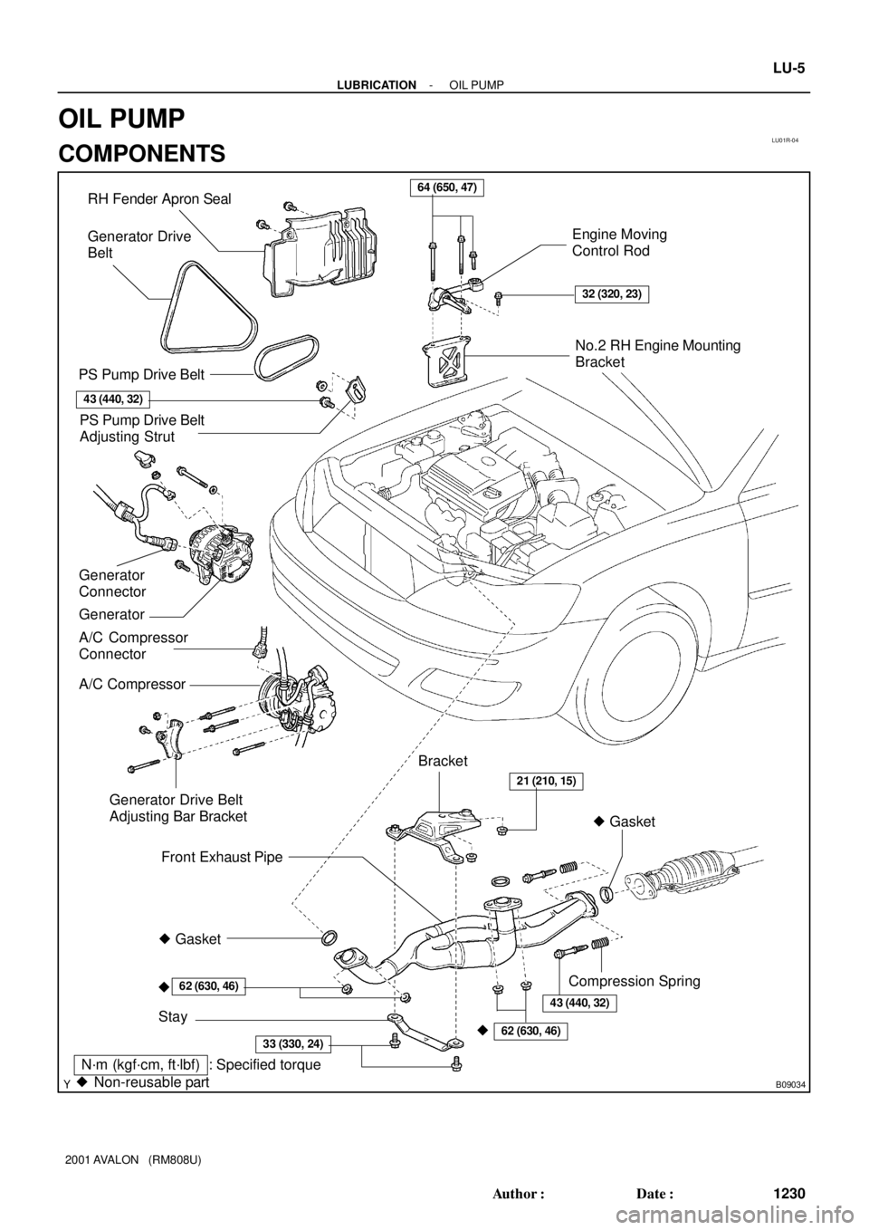
LU01R-04
B09034
� Gasket RH Fender Apron Seal
PS Pump Drive Belt
A/C Compressor
Connector
A/C CompressorEngine Moving
Control Rod
No.2 RH Engine Mounting
Bracket
Front Exhaust Pipe
Stay
�
PS Pump Drive Belt
Adjusting Strut
Generator Drive Belt
Adjusting Bar Bracket
� Gasket
�
62 (630, 46)
33 (330, 24)
21 (210, 15)
64 (650, 47)
32 (320, 23)
62 (630, 46)
N´m (kgf´cm, ft´lbf) : Specified torque
� Non-reusable partBracket Generator Drive
Belt
43 (440, 32)
Compression Spring
Generator Generator
Connector
43 (440, 32)
- LUBRICATIONOIL PUMP
LU-5
1230 Author�: Date�:
2001 AVALON (RM808U)
OIL PUMP
COMPONENTS
Page 1453 of 1897
B06519
B08672
No.2 Timing Belt CoverTiming Belt
Timing Belt Guide
No.2 Generator
Bracket RH Engine Mounting Bracket
Crankshaft
PulleyGasket
Engine Wire
Protector
RH Camshaft Timing Pulley
No.2 Idler Pulley
Crankshaft
Timing PulleyDust Boot
Timing Belt Plate Plate Washer
�
215 (2,200, 159)
43 (440, 32)
27 (280, 20)
Timing Belt TensionerN´m (kgf´cm, ft´lbf) : Specified torque
� Non-reusable part
28 (290, 21)
No.1 Timing Belt Cover
125 (1,300, 94)
*88 (900, 65)
LH Camshaft
Timing Pulley
No.1 Idler Pulley
34 (350, 25)
� Precoated part
* For use with SST
125 (1,300, 94)
LU-6
- LUBRICATIONOIL PUMP
1231 Author�: Date�:
2001 AVALON (RM808U)
Page 1454 of 1897
B08905
N´m (kgf´cm, ft´lbf): Specified torque
� Non-reusable partNo.3 Timing Belt Cover
Gasket
BushingCollar
A/C Compressor
Housing Bracket
Oil Pan Baffle Plate Crankshaft
Position Sensor
Connector Crankshaft
Position
Sensor
Oil PumpEngine Wire
Oil Strainer
No.2 Oil Pan
x 10x 6
x 9� O-Ring
No.1 Oil Pan
� Gasket
Drain Plug
8.5 (85, 74 in.´lbf)
8 (80, 69 in.´lbf)
8 (80, 69 in.´lbf)
10 mm Head 8 (80, 69 in.´lbf)
12 mm Head 19.5 (200, 14)
10 mm Head 8 (80, 69 in.´lbf)
12 mm Head 19.5 (200, 14)
14 mm Head 37.2 (380, 27)
8 (80, 69 in.´lbf)
45 (460, 33)
8 (80, 69 in.´lbf)
x 6
x 17
� Gasket
19.5 (200, 14)
No.1 Exhaust Pipe
Support Bracket
- LUBRICATIONOIL PUMP
LU-7
1232 Author�: Date�:
2001 AVALON (RM808U)