Page 3173 of 3833
REAR WINDOW DEFOGGER
GW-21
C
D
E
F
G
H
J
K
L
MA
B
GW
2. Attach probe circuit tester (in Volt range) to middle portion of
each filament.
3. If a filament is burned out, circuit tester registers 0 or battery
voltage.
4. To locate burned out point, move probe to left and right along fil-
ament.Test needle will swing abruptly when probe passes the
point.
FILAMENT REPAIR
Repair equipment
●Conductive silver composition (Dopant NO.4817 or equivalent)
●Ruler 30 cm(11.8in) long
●Drawing pen
●Heat gun
●Alcohol
●Cloth
Repairing procedure
1. Wipe broken heat wire and its surrounding area clean with a
cloth dampened alcohol.
2. Apply a small amount of conductive silver composition to tip of
drawing pen.
Shake silver composition container before use.
3. Place ruler on glass along broken line.Deposit conductive silver
composition on break with drawing pen.Slightly overlap existing
heat wire on both sides [preferably 5 mm(0.20in)] of the break.
SEL263
SEL265
PIIA0215E
Page 3201 of 3833
DOOR MIRROR
GW-49
C
D
E
F
G
H
J
K
L
MA
B
GW
DOOR MIRRORPFP:96301
Precautions to Handle Retractable Power Door MirrorsEIS004JO
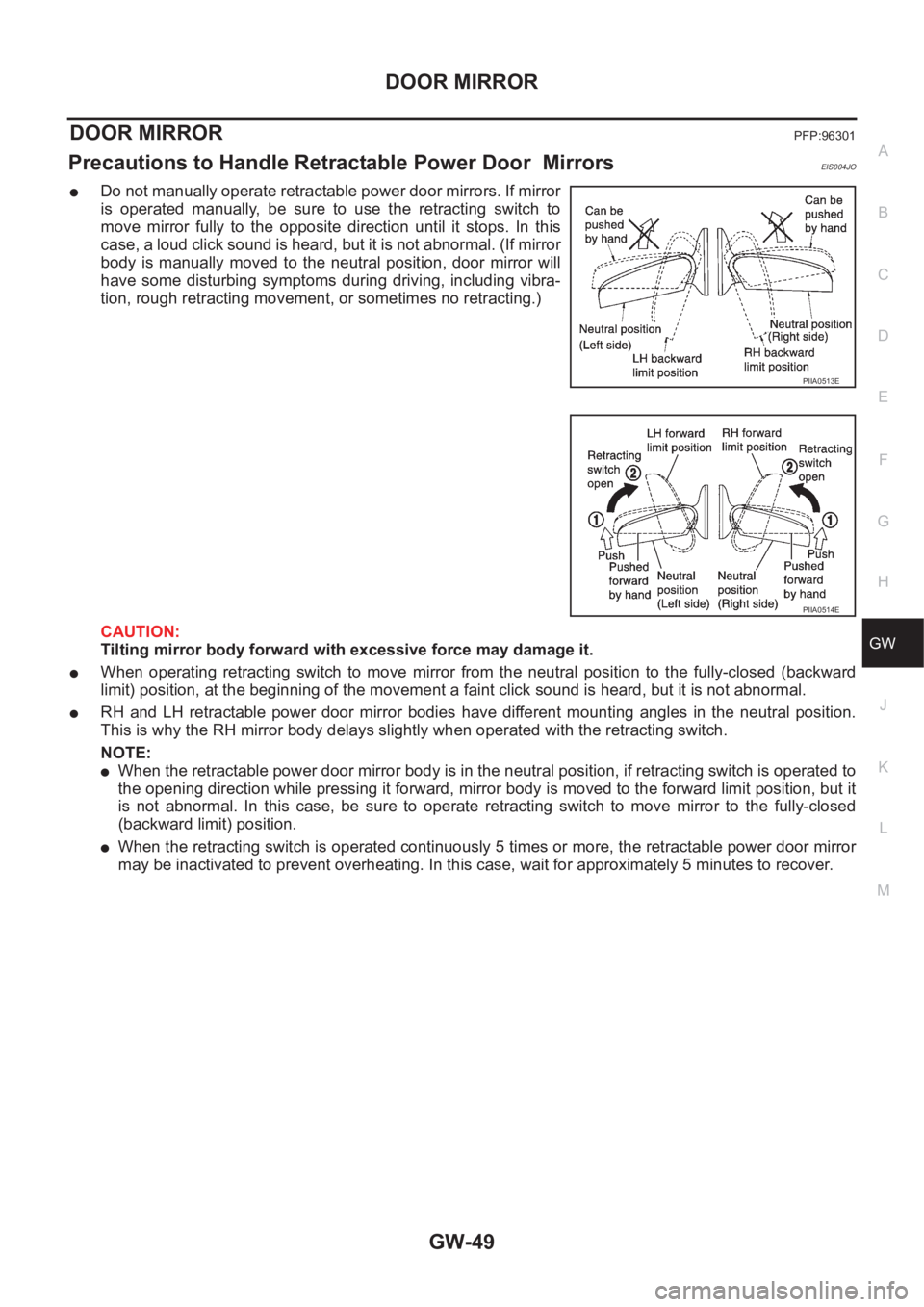
●Do not manually operate retractable power door mirrors. If mirror
is operated manually, be sure to use the retracting switch to
move mirror fully to the opposite direction until it stops. In this
case, a loud click sound is heard, but it is not abnormal. (If mirror
body is manually moved to the neutral position, door mirror will
have some disturbing symptoms during driving, including vibra-
tion, rough retracting movement, or sometimes no retracting.)
CAUTION:
Tilting mirror body forward with excessive force may damage it.
●When operating retracting switch to move mirror from the neutral position to the fully-closed (backward
limit) position, at the beginning of the movement a faint click sound is heard, but it is not abnormal.
●RH and LH retractable power door mirror bodies have different mounting angles in the neutral position.
This is why the RH mirror body delays slightly when operated with the retracting switch.
NOTE:
●When the retractable power door mirror body is in the neutral position, if retracting switch is operated to
the opening direction while pressing it forward, mirror body is moved to the forward limit position, but it
is not abnormal. In this case, be sure to operate retracting switch to move mirror to the fully-closed
(backward limit) position.
●When the retracting switch is operated continuously 5 times or more, the retractable power door mirror
may be inactivated to prevent overheating. In this case, wait for approximately 5 minutes to recover.
PIIA0513E
PIIA0514E
Page 3291 of 3833
PREPARATION
ATC-15
C
D
E
F
G
H
I
K
L
MA
B
AT C
HFC-134a (R-134a) Service Tools and EquipmentEJS00286
Never mix HFC-134a (R-134a) refrigerant and/or its specified lubricant with CFC-12 (R-12) refrigerant and/or
its lubricant.
Separate and non-interchangeable service equipment must be used for handling each type of refrigerant/lubri-
cant.
Refrigerant container fittings, service hose fittings and service equipment fittings (equipment which handles
refrigerant and/or lubricant) are different between CFC-12 (R-12) and HFC-134a (R-134a). This is to avoid
mixed use of the refrigerants/lubricant.
Adapters that convert one size fitting to another must never be used: refrigerant/lubricant contamination will
occur and compressor malfunction will result.
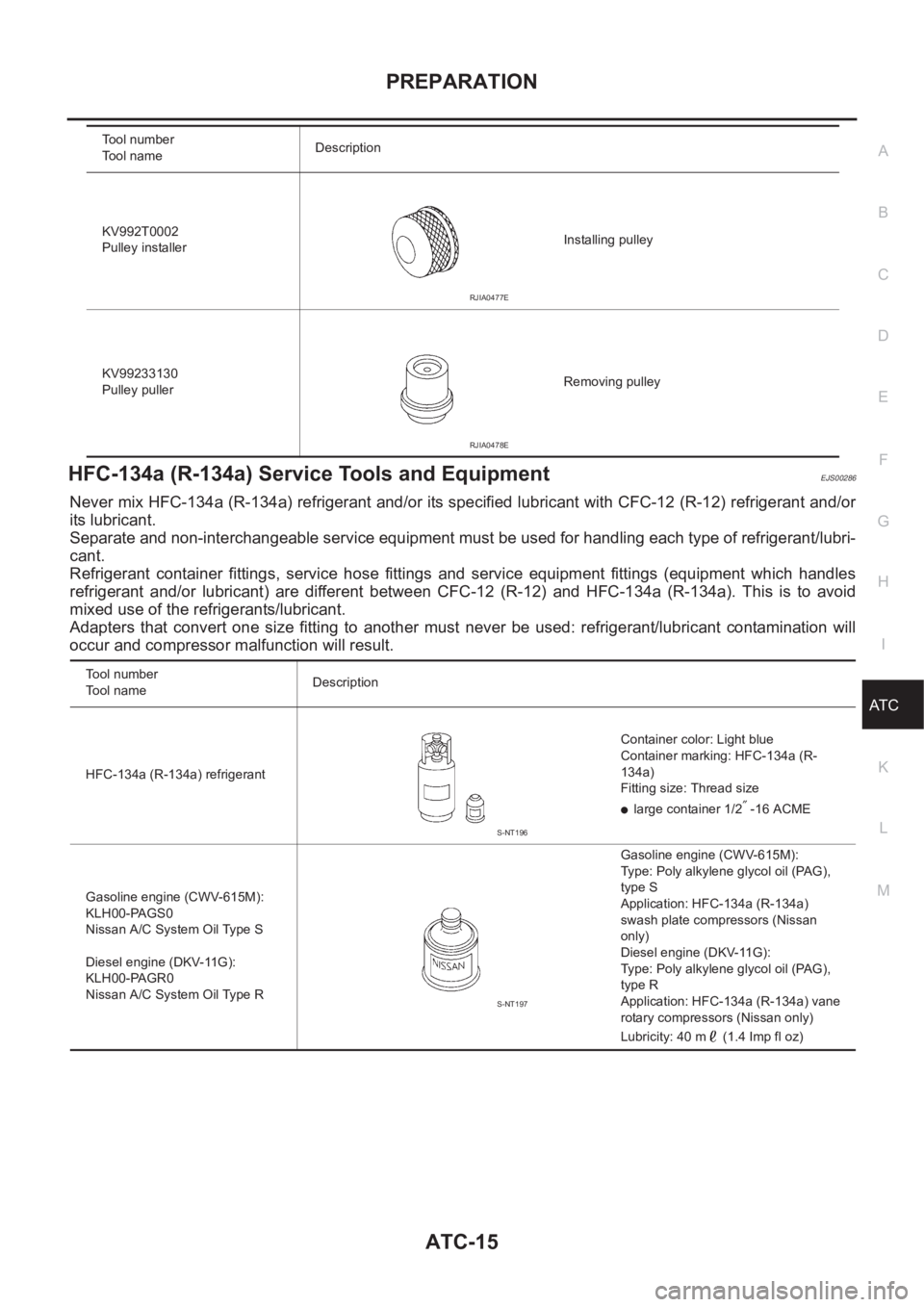
KV992T0002
Pulley installerInstalling pulley
KV99233130
Pulley pullerRemoving pulley Tool number
Tool nameDescription
RJIA0477E
RJIA0478E
Tool number
To o l n a m eDescription
HFC-134a (R-134a) refrigerantContainer color: Light blue
Container marking: HFC-134a (R-
134a)
Fitting size: Thread size
●large container 1/2″ -16 ACME
Gasoline engine (CWV-615M):
KLH00-PAGS0
Nissan A/C System Oil Type S
Diesel engine (DKV-11G):
KLH00-PAGR0
Nissan A/C System Oil Type RGasoline engine (CWV-615M):
Type: Poly alkylene glycol oil (PAG),
type S
Application: HFC-134a (R-134a)
swash plate compressors (Nissan
only)
Diesel engine (DKV-11G):
Type: Poly alkylene glycol oil (PAG),
type R
Application: HFC-134a (R-134a) vane
rotary compressors (Nissan only)
Lubricity: 40 m (1.4 Imp fl oz)
S-NT196
S-NT197
Page 3292 of 3833
ATC-16
PREPARATION
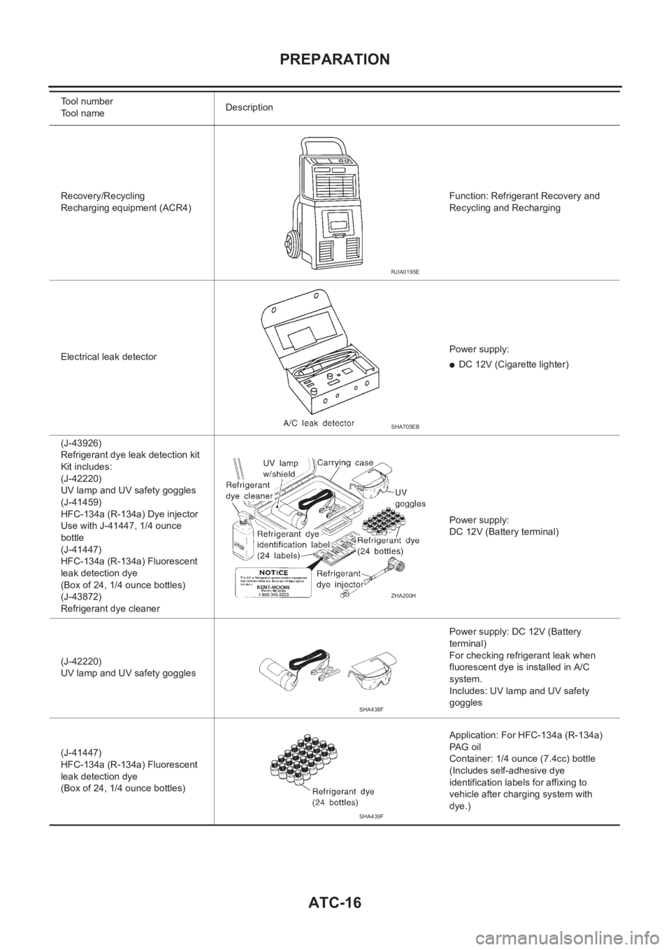
Recovery/Recycling
Recharging equipment (ACR4)Function: Refrigerant Recovery and
Recycling and Recharging
Electrical leak detectorPower supply:
●DC 12V (Cigarette lighter)
(J-43926)
Refrigerant dye leak detection kit
Kit includes:
(J-42220)
UV lamp and UV safety goggles
(J-41459)
HFC-134a (R-134a) Dye injector
Use with J-41447, 1/4 ounce
bottle
(J-41447)
HFC-134a (R-134a) Fluorescent
leak detection dye
(Box of 24, 1/4 ounce bottles)
(J-43872)
Refrigerant dye cleanerPower supply:
DC 12V (Battery terminal)
(J-42220)
UV lamp and UV safety gogglesPower supply: DC 12V (Battery
terminal)
For checking refrigerant leak when
fluorescent dye is installed in A/C
system.
Includes: UV lamp and UV safety
goggles
(J-41447)
HFC-134a (R-134a) Fluorescent
leak detection dye
(Box of 24, 1/4 ounce bottles)Application: For HFC-134a (R-134a)
PAG oil
Container: 1/4 ounce (7.4cc) bottle
(Includes self-adhesive dye
identification labels for affixing to
vehicle after charging system with
dye.) Tool number
Tool nameDescription
RJIA0195E
SHA705EB
ZHA200H
SHA438F
SHA439F
Page 3320 of 3833
ATC-44
TROUBLE DIAGNOSIS
Auto Amp. Terminals and Reference Value
EJS001GW
Measure voltage between each terminal and ground by following
AUTO AMP. INSPECTION TABLE.
PIN CONNECTOR TERMINAL LAYOUT
AUTO AMP. INSPECTION TABLE
RJIA0488E
RJIA0489E
TERMI-
NAL NO.ITEM CONDITIONVo l ta g e
(V)
1 Power supply for IGNIGN
ON-Approx. 12
2 Power supply for BATIGN
OFF-Approx. 12
3GroundIGN
ON-Approx. 0
4 Compressor ON signalIGN
ONCompressor: ON Approx. 0
Compressor: OFF Approx. 4.8
5Power supply for mode
door motor, air mix door
motor, intake door motorIGN
ON-Approx. 12
8 In-vehicle sensor - - -
9Ambient sensor - - -
10 Sunload sensor - - -
11 Illumination ground IGN
ONLight switch: ON Approx. 0
12Power supply for illumina-
tionIGN
ONLight switch: ON Approx. 12
15 LAN signalIGN
ON-Approx. 0
HAK0652D
Page 3327 of 3833
TROUBLE DIAGNOSIS
ATC-51
C
D
E
F
G
H
I
K
L
MA
B
AT C
13.CHECK MALFUNCTIONING SENSOR
Refer to the following chart for malfunctioning code No.
(If two or more sensors malfunction, corresponding code Nos. blink respectively two times.)
*1:Conduct self-diagnosis STEP 2 under sunshine.
When conducting indoors, aim a light (more than 60W) at sunload sensor, otherwise Code No.25 will indicate
despite that sunload sensor is functioning properly.
*2: ATC-100, "
Ambient Sensor Circuit" .
*3: ATC-102, "
In-vehicle Sensor Circuit" .
*4: ATC-108, "
Intake Sensor Circuit" .
*5: ATC-105, "
Sunload Sensor Circuit" .
*6: AT C - 6 4 , "
Air Mix Door Motor Circuit" .
>> INSPECTION END
Code No. Malfunctioning sensor (Including circuits) Reference page
21 / -21 Ambient sensor *2
22 / -22 In-vehicle sensor *3
24 / -24 Intake sensor *4
25 / -25 Sun-load sensor *5
26 / -26 Air mix door motor (LCU) PBR *6
RJIA0493E
Page 3331 of 3833
TROUBLE DIAGNOSIS
ATC-55
C
D
E
F
G
H
I
K
L
MA
B
AT C
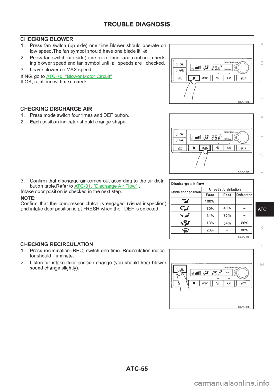
CHECKING BLOWER
1. Press fan switch (up side) one time.Blower should operate on
low speed.The fan symbol should have one blade lit .
2. Press fan switch (up side) one more time, and continue check-
ing blower speed and fan symbol until all speeds are checked.
3. Leave blower on MAX speed.
If NG, go to ATC-70, "
Blower Motor Circuit" .
If OK, continue with next check.
CHECKING DISCHARGE AIR
1. Press mode switch four times and DEF button.
2. Each position indicator should change shape.
3. Confirm that discharge air comes out according to the air distri-
bution table.Refer to AT C - 3 1 , "
Discharge Air Flow" .
Intake door position is checked in the next step.
NOTE:
Confirm that the compressor clutch is engaged (visual inspection)
and intake door position is at FRESH when the DEF is selected.
CHECKING RECIRCULATION
1. Press recirculation (REC) switch one time. Recirculation indica-
tor should illuminate.
2. Listen for intake door position change (you should hear blower
sound change slightly).
RJIA0497E
RJIA0498E
RJIA0492E
RJIA0499E
Page 3369 of 3833
TROUBLE DIAGNOSIS
ATC-93
C
D
E
F
G
H
I
K
L
MA
B
AT C
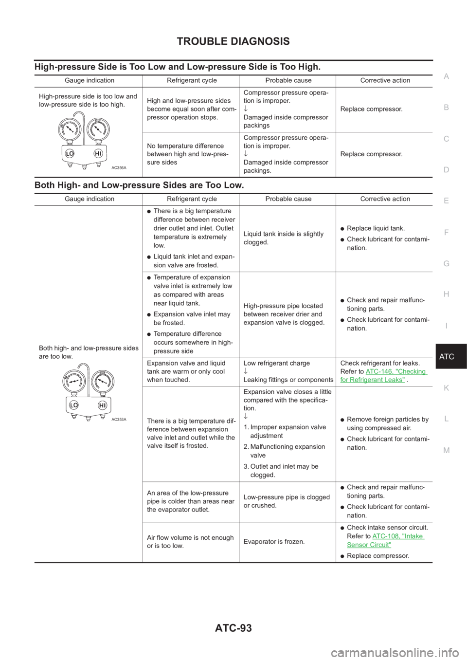
High-pressure Side is Too Low and Low-pressure Side is Too High.
Both High- and Low-pressure Sides are Too Low.
Gauge indication Refrigerant cycle Probable cause Corrective action
High-pressure side is too low and
low-pressure side is too high.High and low-pressure sides
become equal soon after com-
pressor operation stops.Compressor pressure opera-
tion is improper.
↓
Damaged inside compressor
packingsReplace compressor.
No temperature difference
between high and low-pres-
sure sidesCompressor pressure opera-
tion is improper.
↓
Damaged inside compressor
packings.Replace compressor.
AC356A
Gauge indication Refrigerant cycle Probable cause Corrective action
Both high- and low-pressure sides
are too low.
●There is a big temperature
difference between receiver
drier outlet and inlet. Outlet
temperature is extremely
low.
●Liquid tank inlet and expan-
sion valve are frosted.Liquid tank inside is slightly
clogged.
●Replace liquid tank.
●Check lubricant for contami-
nation.
●Temperature of expansion
valve inlet is extremely low
as compared with areas
near liquid tank.
●Expansion valve inlet may
be frosted.
●Temperature difference
occurs somewhere in high-
pressure sideHigh-pressure pipe located
between receiver drier and
expansion valve is clogged.
●Check and repair malfunc-
tioning parts.
●Check lubricant for contami-
nation.
Expansion valve and liquid
tank are warm or only cool
when touched.Low refrigerant charge
↓
Leaking fittings or componentsCheck refrigerant for leaks.
Refer to ATC-146, "
Checking
for Refrigerant Leaks" .
There is a big temperature dif-
ference between expansion
valve inlet and outlet while the
valve itself is frosted.Expansion valve closes a little
compared with the specifica-
tion.
↓
1. Improper expansion valve
adjustment
2. Malfunctioning expansion
valve
3. Outlet and inlet may be
clogged.
●Remove foreign particles by
using compressed air.
●Check lubricant for contami-
nation.
An area of the low-pressure
pipe is colder than areas near
the evaporator outlet.Low-pressure pipe is clogged
or crushed.
●Check and repair malfunc-
tioning parts.
●Check lubricant for contami-
nation.
Air flow volume is not enough
or is too low.Evaporator is frozen.
●Check intake sensor circuit.
Refer to AT C - 1 0 8 , "
Intake
Sensor Circuit"
●Replace compressor.
AC353A