Page 3523 of 3833
FRONT FOG LAMP
LT-33
C
D
E
F
G
H
I
J
L
MA
B
LT
FRONT FOG LAMP PFP:00011
System Description EKS003DF
DESCRIPTION
Power is supplied at all times to fog lamp relay terminal 3
●through 15A fuse (No. 42, located in the fuse and fusible link box).
With the lighting switch in the 2ND position and LOW (“B”) position, power is supplied
●through 10A fuse (No. 31, located in the fuse and fusible link box).
●to lighting switch terminal 11
●through terminal 12 of the lighting switch
●to fog lamp switch terminal 32
●through terminal 31 of the fog lamp switch
●to fog lamp relay terminal 2.
FOG LAMP OPERATION
The fog lamp switch is built into the combination switch. The lighting switch must be in the 1st or 2nd position
for fog lamp operation.
With the fog lamp switch in the ON position, ground is supplied
●to fog lamp relay terminal 1
●through the fog lamp switch and body grounds E24 and E50.
The fog lamp relay is energized and power is supplied
●from fog lamp relay terminal 5
●to terminal 1 of each fog lamp.
Ground is supplied to terminal 2 of each fog lamp through body grounds E24 and E50.
With power and ground supplied, the fog lamps illuminate.
Page 3533 of 3833
REAR COMBINATION LAMP
LT-43
C
D
E
F
G
H
I
J
L
MA
B
LT
Bulb ReplacementEKS00164
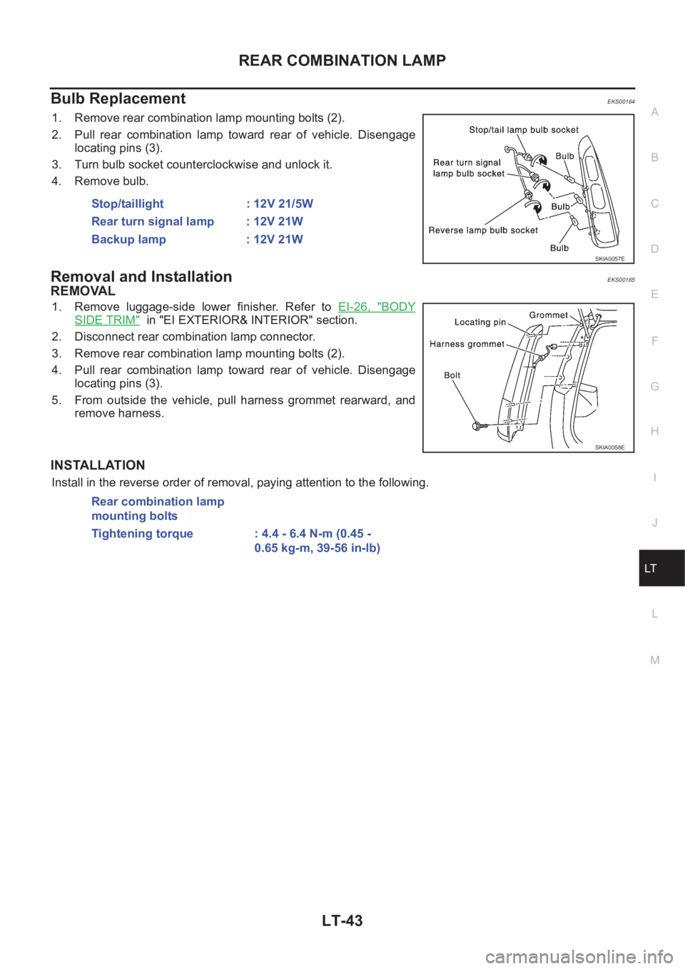
1. Remove rear combination lamp mounting bolts (2).
2. Pull rear combination lamp toward rear of vehicle. Disengage
locating pins (3).
3. Turn bulb socket counterclockwise and unlock it.
4. Remove bulb.
Removal and InstallationEKS00165
REMOVAL
1. Remove luggage-side lower finisher. Refer to EI-26, "BODY
SIDE TRIM" in "EI EXTERIOR& INTERIOR" section.
2. Disconnect rear combination lamp connector.
3. Remove rear combination lamp mounting bolts (2).
4. Pull rear combination lamp toward rear of vehicle. Disengage
locating pins (3).
5. From outside the vehicle, pull harness grommet rearward, and
remove harness.
INSTALLATION
Install in the reverse order of removal, paying attention to the following. Stop/taillight : 12V 21/5W
Rear turn signal lamp : 12V 21W
Backup lamp : 12V 21W
SKIA0057E
SKIA0058E
Rear combination lamp
mounting bolts
Tightening torque : 4.4 - 6.4 N-m (0.45 -
0.65 kg-m, 39-56 in-lb)
Page 3534 of 3833
LT-44
COMBINATION SWITCH
COMBINATION SWITCH
PFP:25567
Removal and InstallationEKS001V6
Refer to SRS-33, "SPIRAL CABLE" in "SUPPLEMENTAL RESTRAINT SYSTEM (SRS)" section for details.
Switch Circuit InspectionEKS001V7
Refer to LT- 2 4 , "Switch Circuit Inspection" in "LIGHTING AND TURN SIGNAL SWITCH" section, and WW-7,
"Terminal and Reference Values for Combination Switch" , WW-15, "Terminal and Reference Values for Com-
bination Switch" in“ WW Wiper/Washer Horn” section for details.
Page 3535 of 3833
![NISSAN X-TRAIL 2001 Service Repair Manual ILLUMINATION
LT-45
C
D
E
F
G
H
I
J
L
MA
B
LT
ILLUMINATIONPFP:27545
System Description EKS003C7
Power is supplied at all times
●through 10A fuse [No. 31, located in the fuse and fusible link box]
● NISSAN X-TRAIL 2001 Service Repair Manual ILLUMINATION
LT-45
C
D
E
F
G
H
I
J
L
MA
B
LT
ILLUMINATIONPFP:27545
System Description EKS003C7
Power is supplied at all times
●through 10A fuse [No. 31, located in the fuse and fusible link box]
●](/manual-img/5/57405/w960_57405-3534.png)
ILLUMINATION
LT-45
C
D
E
F
G
H
I
J
L
MA
B
LT
ILLUMINATIONPFP:27545
System Description EKS003C7
Power is supplied at all times
●through 10A fuse [No. 31, located in the fuse and fusible link box]
●to lighting switch terminal 11.
The lighting switch must be in the 1ST or 2ND position for illumination.
The following chart shows the power and ground connector terminals for the components included in the illu-
mination system.
Component Connector No. Power terminal Ground terminal
Headlamp washier switch M23 3 4
Headlamp aiming switch M24 3 4
Door mirror remote control
switchM26 10 1
ESP off switch M25 3 4
Hazard switch M51 7 8
4WD mode switch M39 4 3
Rear window defogger switch M50 5 6
A/C auto amp. M52 12 11
Combination meter
(LHD models)M46 56 66
Combination meter
(RHD models)M46 45 56
Audio M42 2 1
CD auto changer M82 34 35
Heater control panel M55 2 6
A/T device M58 3 4
Cigarette lighter M56 3 2
Heated seat switch LH
(LHD models)B131 5 6
Heated seat switch RH
(LHD models)B132 5 6
Heated seat switch LH
(RHD models)B35 5 6
Heated seat switch RH
(RHD models)B34 5 6
Page 3560 of 3833
DI-2
Engine Models ........................................................ 35
Inspection/Vehicle speed signal ............................. 35
Inspection/Fuel Level Sensor Unit .......................... 37
FUEL LEVEL SENSOR UNIT .............................. 37
LOW-FUEL WARNING LAMP ............................. 37
The Fuel Gauge Pointer Fluctuates·Indicator
Wrong Value·or Varies. ........................................... 38
The Fuel Gauge Does Not Move to Full-position. ... 39
The Fuel Gauge Does Not Work. ........................... 39
Low Fuel Warning Lamp Illuminate or Not Illuminate ... 40
Electrical Components Inspection .......................... 41
FUEL LEVEL SENSOR UNIT CHECK / GASO-
LINE ENGINE MODELS ...................................... 41
FUEL LEVEL SENSOR UNIT CHECK / DIESEL
ENGINE MODELS ............................................... 41
THERMAL TRANSMITTER CHECK ................... 42
Removal and Installation for Combination Meter .... 42
Disassembly and Assembly for Combination Meter ... 42
WARNING LAMPS .................................................... 43
Schematic ............................................................... 43
Wiring Diagram — WARN —/ LHD Models ............ 44Wiring Diagram — WARN — / RHD Models ........... 50
Electrical Components Inspection ........................... 56
FUEL WARNING LAMP OPERATION CHECK ... 56
OIL PRESSURE SWITCH CHECK ...................... 56
DIODE CHECK .................................................... 56
A/T INDICATOR ......................................................... 57
Wiring Diagram — AT/IND — ................................. 57
WARNING CHIME .................................................. ... 58
System Description ................................................. 58
POWER SUPPLY AND GROUND CIRCUIT ....... 58
IGNITION KEY WARNING CHIME ...................... 58
LIGHT WARNING CHIME ................................... 58
SEAT BELT WARNING CHIME ........................... 58
Wiring Diagram — CHIME — ................................. 59
Symptom Chart ....................................................... 61
Power Supply and Ground Circuit Check ............... 62
Lighting Switch Input Signal Check ......................... 63
Key Switch Insert Signal Check .............................. 65
Door Unlock Sensor Check ..................................... 66
Front Door Switch (driver side) Check .................... 68
CLOCK ...................................................................... 70
Wiring Diagram — CLOCK — ................................. 70
Page 3616 of 3833
DI-58
WARNING CHIME
WARNING CHIME
PFP:24814
System DescriptionEKS002XF
POWER SUPPLY AND GROUND CIRCUIT
Power is supplied at all times
●to combination switch terminal 11 and
●to daytime light control unit terminal 1 (with daytime light system)
●through 10A fuse (No.31, located in fuse and fusible link box), and
●to key switch terminal 1 and
●to time control unit terminal 1
●through 10A fuse [No.28, located in the fuse block (J/B)].
With ignition switch in ON or START position, power is supplied
●to time control unit terminal 17
●through 10A fuse [No.5, located in the fuse block (J/B)].
Ground is supplied
●to time control unit terminal 16
●through body grounds M27 and M70.
IGNITION KEY WARNING CHIME
With ignition switch in OFF or ACC position, and the driver's door open and driver’s door locked, the warning
chime will sound. Power is supplied
●to time control unit terminal 18
●through key switch terminal 2 and
Ground is supplied
●to time control unit terminal 28
●through front door lock actuator (driver side) terminal 5
Front door lock actuator (driver side) terminal 2 is grounded through body grounds M27 and M70, and
Ground is supplied
●to time control unit terminal 30
●through front door switch (driver side) terminal 2.
Front door switch (driver side) terminal 3 is grounded through body grounds B8 and B18.
LIGHT WARNING CHIME
With ignition switch OFF position, driver's door open, and lighting switch in 1ST or 2ND position, warning
chime will sound. Power is supplied
●from the lighting switch terminal 12 or daytime light control unit terminal 11 (with daytime light system)
●to time control unit terminal 19.
Ground is supplied
●to time control unit terminal 30
●through front door switch (driver side) terminal 2.
Front door switch (driver side) terminal 3 is grounded through body grounds B8 and B18.
SEAT BELT WARNING CHIME
When the vehicle speed exceeds 25 km/h (16MPH) with driver side or passenger side seat belt unfastened
(seat belt switch ON), warning chime will sound. Refer to SB-6, "
SEAT BELT WARNING SYSTEM" .
Page 3619 of 3833
WARNING CHIME
DI-61
C
D
E
F
G
H
I
J
L
MA
B
DI
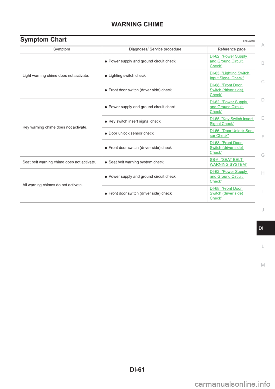
Symptom ChartEKS002XQ
Symptom Diagnoses/ Service procedure Reference page
Light warning chime does not activate.
●Power supply and ground circuit checkDI-62, "
Power Supply
and Ground Circuit
Check"
●Lighting switch checkDI-63, "Lighting Switch
Input Signal Check"
●Front door switch (driver side) checkDI-68, "
Front Door
Switch (driver side)
Check"
Key warning chime does not activate.
●Power supply and ground circuit checkDI-62, "
Power Supply
and Ground Circuit
Check"
●Key switch insert signal checkDI-65, "Key Switch Insert
Signal Check"
●Door unlock sensor checkDI-66, "Door Unlock Sen-
sor Check"
●Front door switch (driver side) checkDI-68, "
Front Door
Switch (driver side)
Check"
Seat belt warning chime does not activate.●Seat belt warning system checkSB-6, "SEAT BELT
WARNING SYSTEM"
All warning chimes do not activate.
●Power supply and ground circuit checkDI-62, "
Power Supply
and Ground Circuit
Check"
●Front door switch (driver side) checkDI-68, "
Front Door
Switch (driver side)
Check"
Page 3621 of 3833
WARNING CHIME
DI-63
C
D
E
F
G
H
I
J
L
MA
B
DI
Lighting Switch Input Signal Check EKS002XU
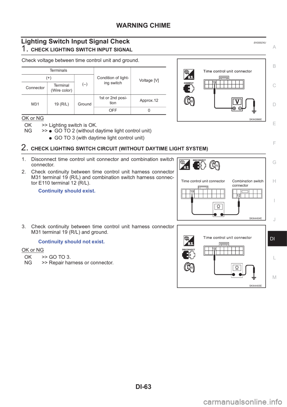
1.CHECK LIGHTING SWITCH INPUT SIGNAL
Check voltage between time control unit and ground.
OK or NG
OK >> Lighting switch is OK.
NG >>
●GO TO 2 (without daytime light control unit)
●GO TO 3 (with daytime light control unit)
2.CHECK LIGHTING SWITCH CIRCUIT (WITHOUT DAYTIME LIGHT SYSTEM)
1. Disconnect time control unit connector and combination switch
connector.
2. Check continuity between time control unit harness connector
M31 terminal 19 (R/L) and combination switch harness connec-
tor E110 terminal 12 (R/L).
3. Check continuity between time control unit harness connector
M31 terminal 19 (R/L) and ground.
OK or NG
OK >> GO TO 3.
NG >> Repair harness or connector.
Te r m i n a l s
Condition of light-
ing switchVoltage [V] (+)
(–)
ConnectorTerminal
(Wire color)
M31 19 (R/L) Ground1st or 2nd posi-
tionApprox.12
OFF 0
SKIA0996E
Continuity should exist.
SKIA4404E
Continuity should not exist.
SKIA4405E