2001 NISSAN X-TRAIL light
[x] Cancel search: lightPage 3381 of 3833
TROUBLE DIAGNOSIS
ATC-105
C
D
E
F
G
H
I
K
L
MA
B
AT C
Sunload Sensor CircuitEJS001HD
COMPONENT DESCRIPTION
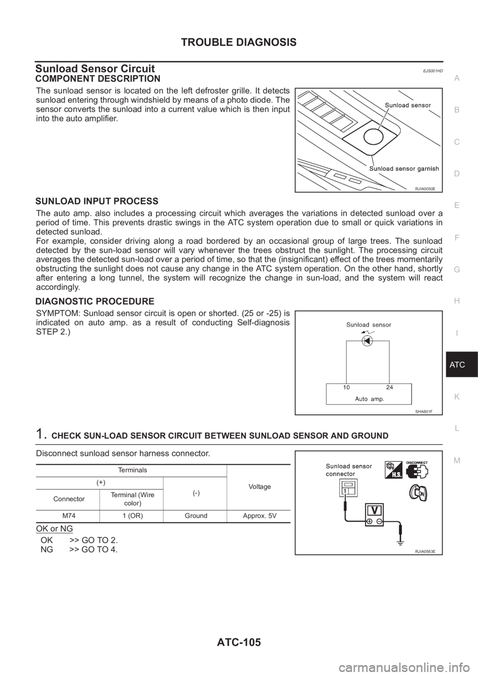
The sunload sensor is located on the left defroster grille. It detects
sunload entering through windshield by means of a photo diode. The
sensor converts the sunload into a current value which is then input
into the auto amplifier.
SUNLOAD INPUT PROCESS
The auto amp. also includes a processing circuit which averages the variations in detected sunload over a
period of time. This prevents drastic swings in the ATC system operation due to small or quick variations in
detected sunload.
For example, consider driving along a road bordered by an occasional group of large trees. The sunload
detected by the sun-load sensor will vary whenever the trees obstruct the sunlight. The processing circuit
averages the detected sun-load over a period of time, so that the (insignificant) effect of the trees momentarily
obstructing the sunlight does not cause any change in the ATC system operation. On the other hand, shortly
after entering a long tunnel, the system will recognize the change in sun-load, and the system will react
accordingly.
DIAGNOSTIC PROCEDURE
SYMPTOM: Sunload sensor circuit is open or shorted. (25 or -25) is
indicated on auto amp. as a result of conducting Self-diagnosis
STEP 2.)
1.CHECK SUN-LOAD SENSOR CIRCUIT BETWEEN SUNLOAD SENSOR AND GROUND
Disconnect sunload sensor harness connector.
OK or NG
OK >> GO TO 2.
NG >> GO TO 4.
RJIA0050E
SHA601F
Te r m i n a l s
Voltage (+)
(-)
ConnectorTe r m i n a l ( W i r e
color)
M74 1 (OR) Ground Approx. 5V
RJIA0563E
Page 3397 of 3833
VENTILATION AIR FILTER
ATC-121
C
D
E
F
G
H
I
K
L
MA
B
AT C
VENTILATION AIR FILTER PFP:27277
Removal and InstallationEJS000UP
FUNCTION
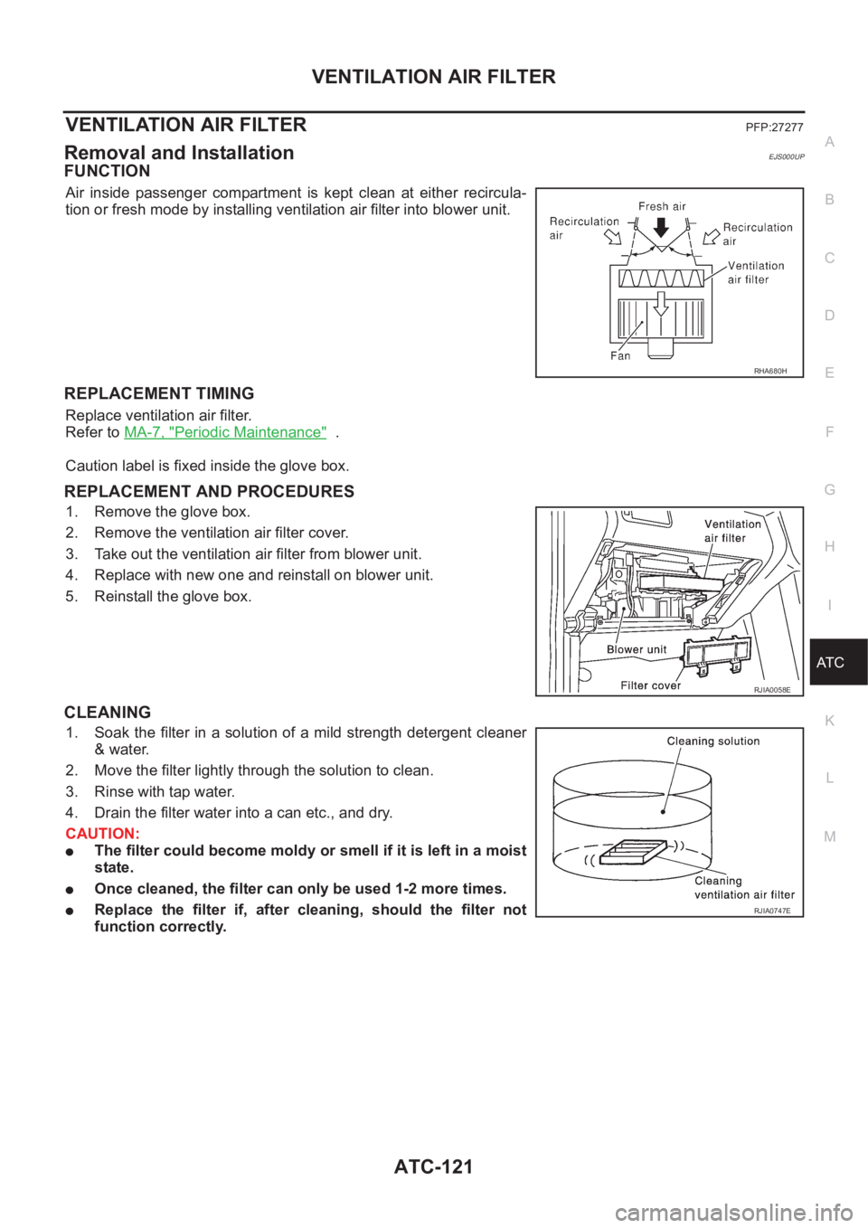
Air inside passenger compartment is kept clean at either recircula-
tion or fresh mode by installing ventilation air filter into blower unit.
REPLACEMENT TIMING
Replace ventilation air filter.
Refer to MA-7, "
Periodic Maintenance" .
Caution label is fixed inside the glove box.
REPLACEMENT AND PROCEDURES
1. Remove the glove box.
2. Remove the ventilation air filter cover.
3. Take out the ventilation air filter from blower unit.
4. Replace with new one and reinstall on blower unit.
5. Reinstall the glove box.
CLEANING
1. Soak the filter in a solution of a mild strength detergent cleaner
& water.
2. Move the filter lightly through the solution to clean.
3. Rinse with tap water.
4. Drain the filter water into a can etc., and dry.
CAUTION:
●The filter could become moldy or smell if it is left in a moist
state.
●Once cleaned, the filter can only be used 1-2 more times.
●Replace the filter if, after cleaning, should the filter not
function correctly.
RHA680H
RJIA0058E
RJIA0747E
Page 3423 of 3833
REFRIGERANT LINES
ATC-147
C
D
E
F
G
H
I
K
L
MA
B
AT C
Checking System for Leaks Using the Fluorescent Leak DetectorEJS000VK
1. Check A/C system for leaks using the UV lamp and safety goggles (J-42220) in a low sunlight area (area
without windows preferable). Illuminate all components, fittings and lines. The dye will appear as a bright
green/yellow area at the point of leakage. Fluorescent dye observed at the evaporator drain opening indi-
cates an evaporator core assembly (tubes, core or expansion valve) leak.
2. If the suspected area is difficult to see, use an adjustable mirror or wipe the area with a clean shop rag or
cloth, with the UV lamp for dye residue.
3. After the leak is repaired, remove any residual dye using dye cleaner (J-43872) to prevent future misdiag-
nosis.
4. Perform a system performance check and verify the leak repair with an approved electronic refrigerant
leak detector.
NOTE:
Other gases in the work area or substances on the A/C components, for example, anti-freeze, windshield
washer fluid, solvents and lubricants, may falsely trigger the leak detector. Make sure the surfaces to be
checked are clean.
Clean with a dry cloth or blow off with shop air.
Do not allow the sensor tip of the detector to contact with any substance. This can also cause false readings
and may damage the detector.
Dye InjectionEJS000VL
(This procedure is only necessary when recharging the system or when the compressor has seized and was
replaced.)
1. Check A/C system static (at rest) pressure. Pressure must be at least 345 kPa (50 psi).
2. Pour one bottle (1/4 ounce / 7.4 cc) of the A/C refrigerant dye into the injector tool (J-41459).
3. Connect the injector tool to the A/C LOW PRESSURE side service fitting.
4. Start engine and switch A/C ON.
5. When the A/C operating (compressor running), inject one bottle (1/4 ounce / 7.4 cc) of fluorescent dye
through the low-pressure service valve using dye injector tool J-41459 (refer to the manufacture's operat-
ing instructions).
6. With the engine still running, disconnect the injector tool from the service fitting.
CAUTION:
Be careful the A/C system or replacing a component, pour the dye directly into the open system con-
nection and proceed with the service procedures.
7. Operate the A/C system for a minimum of 20 minutes to mix the dye with the system oil. Depending on the
leak size, operating conditions and location of the leak, it may take from minutes to days for the dye to
penetrate a leak and become visible.
Electronic Refrigerant Leak DetectorEJS000VM
PRECAUTIONS FOR HANDLING LEAK DETECTOR
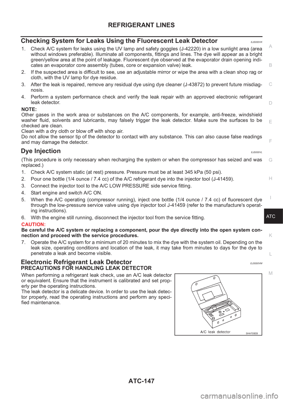
When performing a refrigerant leak check, use an A/C leak detector
or equivalent. Ensure that the instrument is calibrated and set prop-
erly per the operating instructions.
The leak detector is a delicate device. In order to use the leak detec-
tor properly, read the operating instructions and perform any speci-
fied maintenance.
SHA705EB
Page 3433 of 3833
TROUBLE DIAGNOSIS
MTC-7
C
D
E
F
G
H
I
K
L
MA
B
MTC
Operational CheckEJS001FE
The purpose of the operational check is to confirm that the system operates properly.
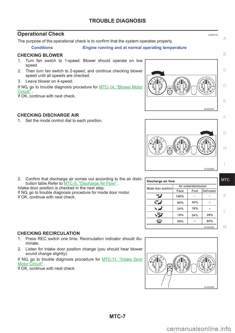
CHECKING BLOWER
1. Turn fan switch to 1-speed. Blower should operate on low
speed.
2. Then turn fan switch to 2-speed, and continue checking blower
speed until all speeds are checked.
3. Leave blower on 4-speed.
If NG, go to trouble diagnosis procedure for MTC-14, "
Blower Motor
Circuit" .
If OK, continue with next check.
CHECKING DISCHARGE AIR
1. Set the mode control dial to each position.
2. Confirm that discharge air comes out according to the air distri-
bution table.Refer to MTC-5, "
Discharge Air Flow" .
Intake door position is checked in the next step.
If NG, go to trouble diagnosis procedure for mode door motor.
If OK, continue with next check.
CHECKING RECIRCULATION
1. Press REC switch one time. Recirculation indicator should illu-
minate.
2. Listen for intake door position change (you should hear blower
sound change slightly).
If NG, go to trouble diagnosis procedure for MTC-11, "
Intake Door
Motor Circuit" .
If OK, continue with next check.Conditions :Engine running and at normal operating temperature
RJIA0587E
RJIA0588E
RJIA0492E
RJIA0589E
Page 3486 of 3833
SC-30
STARTING SYSTEM
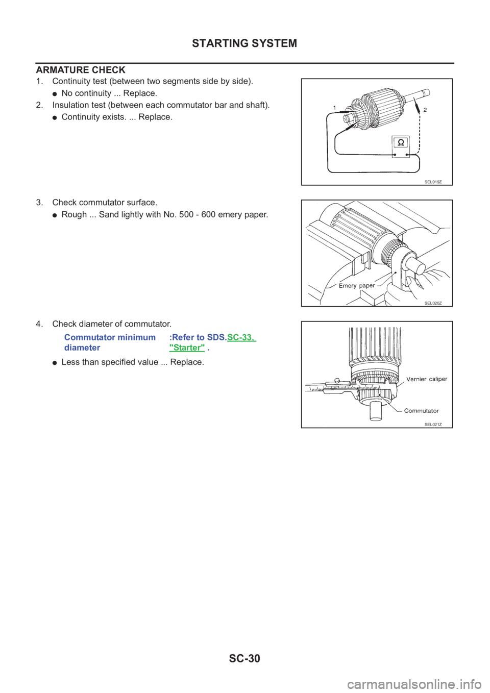
ARMATURE CHECK
1. Continuity test (between two segments side by side).
●No continuity ... Replace.
2. Insulation test (between each commutator bar and shaft).
●Continuity exists. ... Replace.
3. Check commutator surface.
●Rough ... Sand lightly with No. 500 - 600 emery paper.
4. Check diameter of commutator.
●Less than specified value ... Replace.
SEL019Z
SEL020Z
Commutator minimum
diameter:Refer to SDS.SC-33,
"Starter" .
SEL021Z
Page 3491 of 3833
LT-1
LIGHTING SYSTEM
K ELECTRICAL
CONTENTS
C
D
E
F
G
H
I
J
L
M
SECTION
A
B
LT
LIGHTING SYSTEM
PRECAUTION ............................................................ 3
Precautions for Supplemental Restraint System
(SRS) “AIR BAG” and “SEAT BELT PRE-TEN-
SIONER” .................................................................. 3
Precaution ................................................................ 3
Wiring Diagrams and Trouble Diagnosis .................. 3
HEADLAMP ................................................................ 4
System Description .................................................. 4
DESCRIPTION ...................................................... 4
LOW BEAM OPERATION ..................................... 4
HIGH BEAM OPERATION/FLASH-TO-PASS
OPERATION ......................................................... 4
Wiring Diagram — H/LAMP — ................................. 5
Trouble Diagnoses ................................................... 6
Aiming Adjustment ................................................... 6
LOW BEAM ........................................................... 7
Bulb Replacement .................................................... 8
HEAD LAMP ......................................................... 8
CLEARANCE LAMP ............................................. 8
Removal and Installation .......................................... 8
REMOVAL ............................................................. 8
INSTALLATION ..................................................... 8
HEADLAMP - DAYTIME LIGHT SYSTEM - ............... 9
System Description .................................................. 9
DESCRIPTION ...................................................... 9
HEADLAMP OPERATION (DAYTIME LIGHT
CANCEL OPERATION) ........................................ 9
DAYTIME LIGHT OPERATION ............................. 9
Schematic .............................................................. 10
Wiring Diagram -DTRL- ........................................... 11
Trouble Diagnoses ................................................. 14
DAYTIME LIGHT CONTROL UNIT INSPECTION
TABLE ................................................................. 14
Bulb Replacement .................................................. 14
Aiming Adjustment ................................................. 14
HEADLAMP AIMING CONTROL ............................. 15
Wiring Diagram -H/AIM- ......................................... 15
Removal and Installation ........................................ 16
Switch Circuit Inspection ........................................ 16
TURN SIGNAL AND HAZARD WARNING LAMPS ... 17System Description ................................................. 17
TURN SIGNAL OPERATION .............................. 17
HAZARD LAMP OPERATION ............................. 17
Wiring Diagram — TURN — ................................... 19
Trouble Diagnoses ................................................. 21
Electrical Components Inspection .......................... 21
COMBINATION FLASHER UNIT CHECK ........
... 21
Bulb Replacement .................................................. 22
FRONT TURN SIGNAL LAMP ............................ 22
SIDE TURN SIGNAL LAMP ................................ 22
REAR TURN SIGNAL LAMP .............................. 22
Removal and Installation for Front Turn Signal Lamp ... 22
REMOVAL ........................................................... 22
INSTALLATION ................................................... 22
Removal and Installation for Side Turn Signal Lamp ... 23
Removal and Installation for Rear Turn Signal Lamp ... 23
LIGHTING AND TURN SIGNAL SWITCH ................ 24
Removal and Installation ........................................ 24
Switch Circuit Inspection ........................................ 24
HAZARD SWITCH .................................................... 25
Removal and Installation ........................................ 25
REMOVAL ........................................................... 25
INSTALLATION ................................................... 25
STOP LAMP .............................................................. 26
Wiring Diagram — STOP/L — ................................ 26
Bulb Replacement .................................................. 27
STOP LAMP ........................................................ 27
HIGH-MOUNTED STOP LAMP ........................... 27
Removal and Installation ........................................ 27
STOP LAMP ........................................................ 27
HIGH-MOUNTED STOP LAMP ........................... 27
BACK-UP LAMP ....................................................... 28
Wiring Diagram — BACK/L — ................................ 28
Bulb Replacement .................................................. 29
Removal and Installation ........................................ 29
PARKING, LICENSE PLATE AND TAIL LAMPS ..... 30
Wiring Diagram — TAIL/L — .................................. 30
Bulb Replacement .................................................. 32
PARKING AND TAIL LAMPS .............................. 32
Page 3494 of 3833
LT-4
HEADLAMP
HEADLAMP
PFP:26010
System Description EKS003CD
DESCRIPTION
The headlamps are controlled by the lighting switch which is built into the combination switch.
Power is supplied at all times
●to lighting switch terminal 8
●through 15A fuse (No. 40, located in the fuse and fusible link box), and
●to lighting switch terminal 5
●through 15A fuse (No. 41, located in the fuse and fusible link box).
LOW BEAM OPERATION
When the lighting switch is turned to the 2ND position and placed in LOW (“B”) position, power is supplied
●from lighting switch terminal 10
●to terminal 3 of the headlamp LH, and
●from lighting switch terminal 7
●to terminal 3 of the headlamp RH.
Terminal 2 of each headlamp supplies ground through body grounds E24 and E50.
With power and ground supplied, the low beams will illuminate.
HIGH BEAM OPERATION/FLASH-TO-PASS OPERATION
When the lighting switch is turned to the 2ND position and placed in HIGH (“A”) position or PASS (“C”) posi-
tion, power is supplied
●from lighting switch terminal 6
●to terminal 1 of headlamp RH, and
●from lighting switch terminal 9
●to terminal 1 of headlamp LH, and
●to combination meter terminal 61 (LHD models) or 50 (RHD models) for the HIGH BEAM indicator.
Ground is supplied to terminal 60 (LHD models) or 49 (RHD models) of the combination meter through body
grounds M27 and M70.
Ground is supplied to terminal 2 of each headlamp through body grounds E24 and E50.
With power and ground supplied, the high beams and the HIGH BEAM indicator illuminate.
SMA for models with roof mounted driving lamp
Page 3496 of 3833
LT-6
HEADLAMP
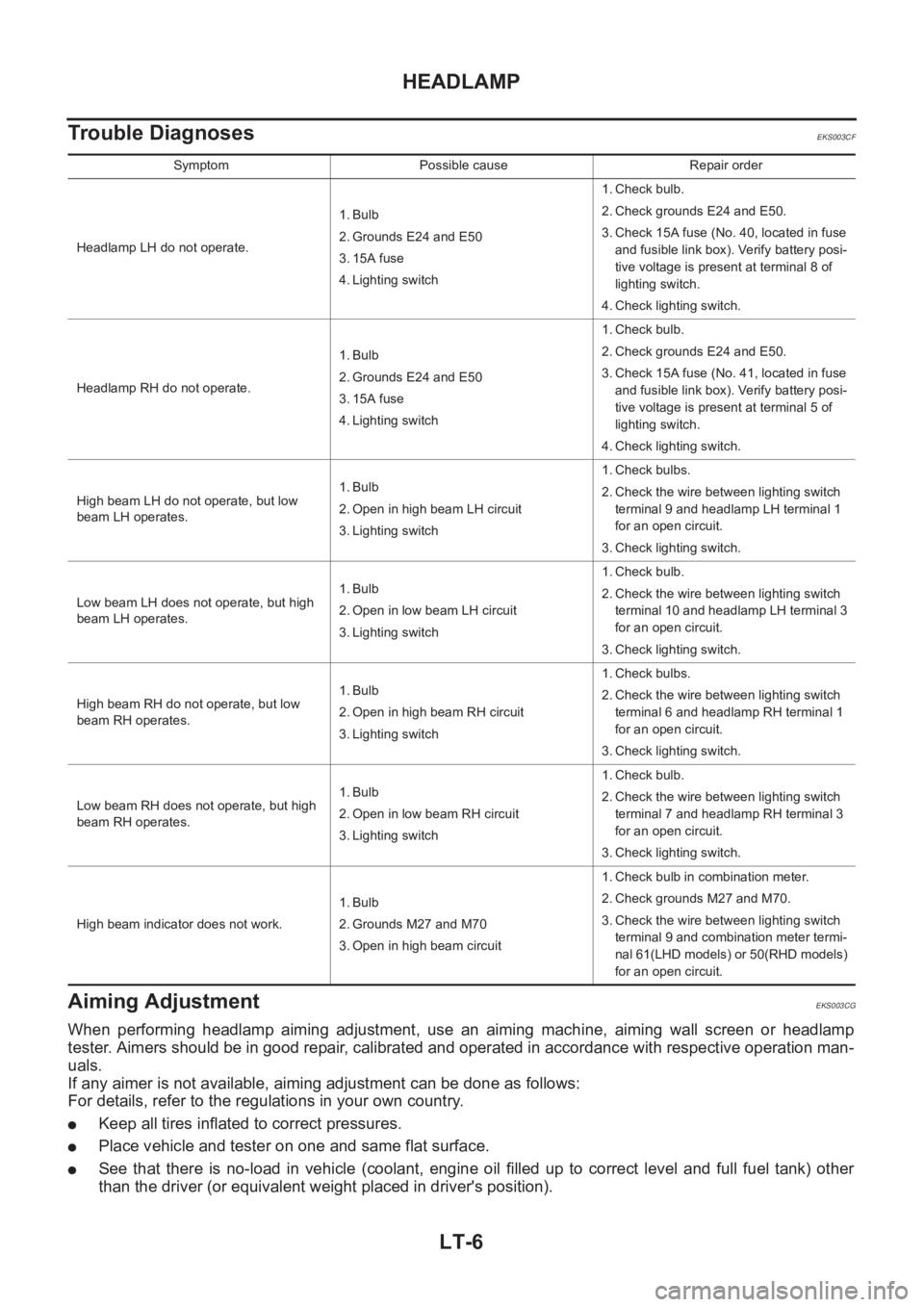
Trouble Diagnoses
EKS003CF
Aiming Adjustment EKS003CG
When performing headlamp aiming adjustment, use an aiming machine, aiming wall screen or headlamp
tester. Aimers should be in good repair, calibrated and operated in accordance with respective operation man-
uals.
If any aimer is not available, aiming adjustment can be done as follows:
For details, refer to the regulations in your own country.
●Keep all tires inflated to correct pressures.
●Place vehicle and tester on one and same flat surface.
●See that there is no-load in vehicle (coolant, engine oil filled up to correct level and full fuel tank) other
than the driver (or equivalent weight placed in driver's position).
Symptom Possible cause Repair order
Headlamp LH do not operate.1. Bulb
2. Grounds E24 and E50
3. 15A fuse
4. Lighting switch1. Check bulb.
2. Check grounds E24 and E50.
3. Check 15A fuse (No. 40, located in fuse
and fusible link box). Verify battery posi-
tive voltage is present at terminal 8 of
lighting switch.
4. Check lighting switch.
Headlamp RH do not operate.1. Bulb
2. Grounds E24 and E50
3. 15A fuse
4. Lighting switch1. Check bulb.
2. Check grounds E24 and E50.
3. Check 15A fuse (No. 41, located in fuse
and fusible link box). Verify battery posi-
tive voltage is present at terminal 5 of
lighting switch.
4. Check lighting switch.
High beam LH do not operate, but low
beam LH operates.1. Bulb
2. Open in high beam LH circuit
3. Lighting switch1. Check bulbs.
2. Check the wire between lighting switch
terminal 9 and headlamp LH terminal 1
for an open circuit.
3. Check lighting switch.
Low beam LH does not operate, but high
beam LH operates.1. Bulb
2. Open in low beam LH circuit
3. Lighting switch1. Check bulb.
2. Check the wire between lighting switch
terminal 10 and headlamp LH terminal 3
for an open circuit.
3. Check lighting switch.
High beam RH do not operate, but low
beam RH operates.1. Bulb
2. Open in high beam RH circuit
3. Lighting switch1. Check bulbs.
2. Check the wire between lighting switch
terminal 6 and headlamp RH terminal 1
for an open circuit.
3. Check lighting switch.
Low beam RH does not operate, but high
beam RH operates.1. Bulb
2. Open in low beam RH circuit
3. Lighting switch1. Check bulb.
2. Check the wire between lighting switch
terminal 7 and headlamp RH terminal 3
for an open circuit.
3. Check lighting switch.
High beam indicator does not work.1. Bulb
2. Grounds M27 and M70
3. Open in high beam circuit1. Check bulb in combination meter.
2. Check grounds M27 and M70.
3. Check the wire between lighting switch
terminal 9 and combination meter termi-
nal 61(LHD models) or 50(RHD models)
for an open circuit.