2001 NISSAN X-TRAIL light
[x] Cancel search: lightPage 3025 of 3833
TROUBLE DIAGNOSIS
SRS-23
C
D
E
F
G
I
J
K
L
MA
B
SRS
Trouble Diagnoses Without CONSULT-IIEHS000OA
DIAGNOSTIC PROCEDURE 4
CAUTION:
SRS will not enter diagnosis mode if no malfunction is detected in user mode.
1. Turn ignition switch “ON”.
2. After “AIR BAG” warning lamp lights for 7seconds, turn ignition switch “OFF” within 1seconds.
3. Wait more than 3 seconds.
4. Repeat the steps 1 to 3 two times.
5. Turn ignition switch ON”.
6. Compare the number of flashes to Air Bag Warning Lamp Flash Code.
7. Turn the ignition switch OFF, and disconnect both battery cables.
8. Repair the system as outlined by the “REPAIR ORDER” in “Warning Lamp Flash Code Chart” that corre-
sponds to flash code.
9. After the repairing of malfunction, connect both battery cables, and turn the ignition switch ON.
10. Check that no malfunction is detected.
Page 3036 of 3833
SRS-34
SPIRAL CABLE
6. Remove the spiral cable fixing screws, and while pushing the upper plastic tab, remove the spiral cable.
CAUTION:
●Do not attempt to disassemble spiral cable.
●Do not apply lubricant to the spiral cable.
7. Remove the wiper washer switch and lighting switch from the spiral cable.
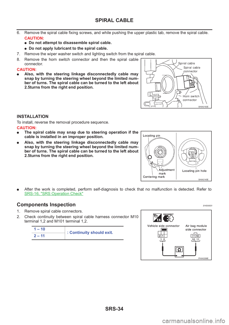
8. Remove the horn switch connector and then the spiral cable
connector.
CAUTION:
●Also, with the steering linkage disconnectedly cable may
snap by turning the steering wheel beyond the limited num-
ber of turns. The spiral cable can be turned to the left about
2.5turns from the right end position.
INSTALLATION
To install, reverse the removal procedure sequence.
CAUTION:
●The spiral cable may snap due to steering operation if the
cable is installed in an improper position.
●Also, with the steering linkage disconnectedly cable may
snap by turning the steering wheel beyond the limited num-
ber of turns. The spiral cable can be turned to the left about
2.5turns from the right end position.
●After the work is completed, perform self-diagnosis to check that no malfunction is detected. Refer to
SRS-16, "
SRS Operation Check"
Components InspectionEHS000DI
1. Remove spiral cable connectors.
2. Check continuity between spiral cable harness connector M10
terminal 1,2 and M101 terminal 1,2.
SHIA0193E
SHIA0145E
1 – 10
: Continuity should exit.
2 – 11
PHIA0298E
Page 3043 of 3833
DISPOSAL OF AIR BAG MODULE AND SEAT BELT PRE-TENSIONER
SRS-41
C
D
E
F
G
I
J
K
L
MA
B
SRS
DISPOSAL OF AIR BAG MODULE AND SEAT BELT PRE-TENSIONERPFP:00014
Caution for Air Bag Module and Seat Belt Pre-tensioner EHS000DE
●Before disposing of air bag module and seat belt pre-tensioner, or vehicles equipped with such systems,
deploy the systems. If such systems have already been deployed due to an accident, dispose of them as
indicated in SRS-46, "
DISPOSING OF AIR BAG MODULE AND SEAT BELT PRE-TENSIONER"
●When deploying the air bag module and seat belt pre-tensioner, always use the Special Service Tool;
Deployment tool (KV99106400).
●When deploying the air bag module and seat belt pre-tensioner, stand at least 5 m (16 ft) away from the
deployment component.
●When deploying air bag module and seat belt pre-tensioner, a fairly loud noise is made, followed by
smoke being released. The smoke is not poisonous, however, be careful not to inhale smoke since it irri-
tates the throat and can cause choking.
●Always activate one air bag module at a time.
●Due to heat, leave air bag module unattended for more than 30 minutes after deployment. Also leave seat
belt pre-tensioner unattended for more than 10 minutes after deployment.
●Be sure to wear gloves when handling a deployed air bag module and seat belt pre-tensioner.
●Never apply water to the deployed air bag module and seat belt pre-tensioner.
●Wash your hands clean after finishing work.
●Place the vehicle outdoors with an open space of at least 6 m (20 ft) on all sides when deploying air bag
module and seat belt pre-tensioner while mounted in vehicle.
●Use a voltmeter to make sure the vehicle battery is fully charged.
●Do not dispose of the air bag module and seat belt pre-tensioner un-deployed.
CHECKING DEPLOYMENT TOOL
Connecting To Battery
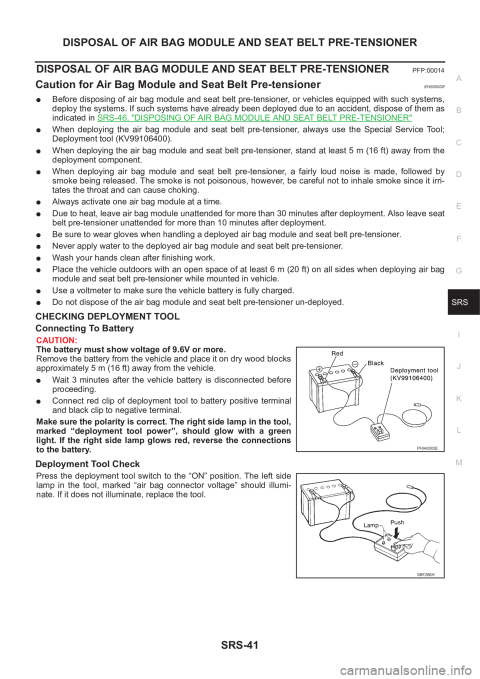
CAUTION:
The battery must show voltage of 9.6V or more.
Remove the battery from the vehicle and place it on dry wood blocks
approximately 5 m (16 ft) away from the vehicle.
●Wait 3 minutes after the vehicle battery is disconnected before
proceeding.
●Connect red clip of deployment tool to battery positive terminal
and black clip to negative terminal.
Make sure the polarity is correct. The right side lamp in the tool,
marked “deployment tool power”, should glow with a green
light. If the right side lamp glows red, reverse the connections
to the battery.
Deployment Tool Check
Press the deployment tool switch to the “ON” position. The left side
lamp in the tool, marked “air bag connector voltage” should illumi-
nate. If it does not illuminate, replace the tool.
PHIA0003E
SBF266H
Page 3057 of 3833
HOOD
BL-5
C
D
E
F
G
H
J
K
L
MA
B
BL
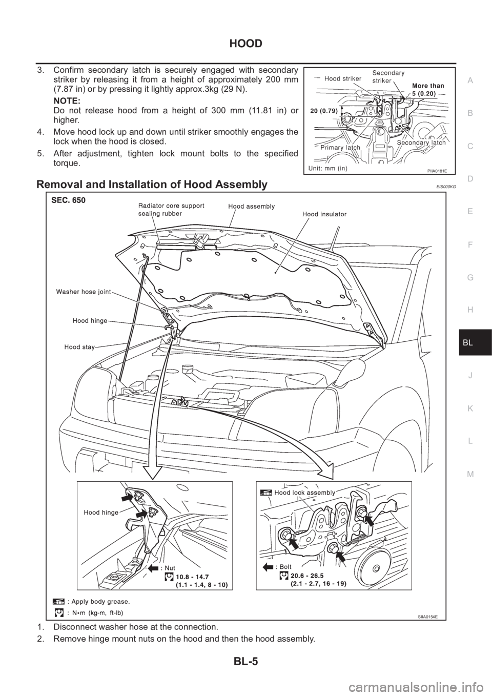
3. Confirm secondary latch is securely engaged with secondary
striker by releasing it from a height of approximately 200 mm
(7.87 in) or by pressing it lightly approx.3kg (29 N).
NOTE:
Do not release hood from a height of 300 mm (11.81 in) or
higher.
4. Move hood lock up and down until striker smoothly engages the
lock when the hood is closed.
5. After adjustment, tighten lock mount bolts to the specified
torque.
Removal and Installation of Hood AssemblyEIS000KG
1. Disconnect washer hose at the connection.
2. Remove hinge mount nuts on the hood and then the hood assembly.
PIIA0181E
SIIA0154E
Page 3133 of 3833
NATS (NISSAN ANTI-THEFT SYSTEM)
BL-81
C
D
E
F
G
H
J
K
L
MA
B
BL
System DescriptionEIS001RR
NATS (Nissan Anti-Theft System) has the following immobilizer functions:
●Since only NATS ignition keys, whose ID nos. have been registered into the ECM and IMMU of NATS,
allow the engine to run, operation of a stolen vehicle without a NATS registered key is prevented by
NATS.
That is to say, NATS will immobilize the engine if someone tries to start it without the registered key of
NATS.
●This version of NATS has dongle unit to improve its anti-theft performance (RHD models). Dongle unit has
its own ID which is registered into NATS IMMU. So if dongle unit is replaced, initialization must be carried
out.
●When malfunction of dongle unit is detected:
The security indicator lamp illuminates for about 15 minutes after ignition switch is turned to ON.
–When dongle unit has a malfunction and the indicator lamp is illuminated, engine can not be started. How-
ever engine can be started only one time when security indicator lamp turns off in about 15 minutes after
ignition switch is turned to ON.
●All of the originally supplied ignition key IDs have been NATS registered.
If requested by the vehicle owner, a maximum of five key IDs can be registered into the NATS compo-
nents.
●The security indicator blinks when the ignition switch is in “OFF” or “ACC” position. Therefore, NATS
warns outsiders that the vehicle is equipped with the anti-theft system.
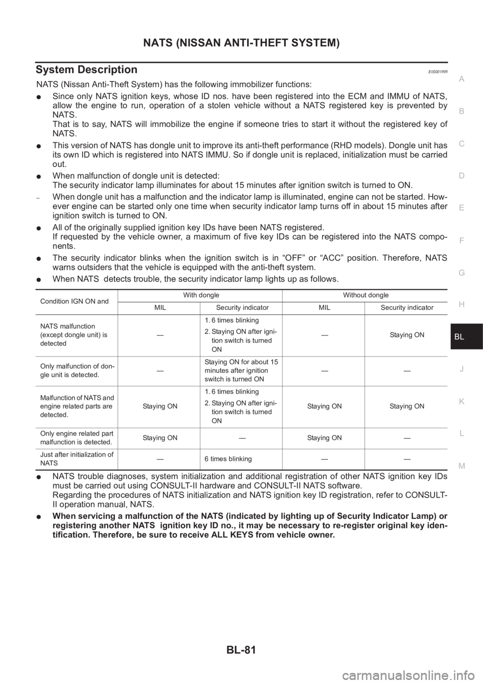
●When NATS detects trouble, the security indicator lamp lights up as follows.
●NATS trouble diagnoses, system initialization and additional registration of other NATS ignition key IDs
must be carried out using CONSULT-II hardware and CONSULT-II NATS software.
Regarding the procedures of NATS initialization and NATS ignition key ID registration, refer to CONSULT-
II operation manual, NATS.
●When servicing a malfunction of the NATS (indicated by lighting up of Security Indicator Lamp) or
registering another NATS ignition key ID no., it may be necessary to re-register original key iden-
tification. Therefore, be sure to receive ALL KEYS from vehicle owner.
Condition IGN ON andWith dongle Without dongle
MIL Security indicator MIL Security indicator
NATS malfunction
(except dongle unit) is
detected—1. 6 times blinking
2. Staying ON after igni-
tion switch is turned
ON— Staying ON
Only malfunction of don-
gle unit is detected.—Staying ON for about 15
minutes after ignition
switch is turned ON——
Malfunction of NATS and
engine related parts are
detected.Staying ON1. 6 times blinking
2. Staying ON after igni-
tion switch is turned
ONStaying ON Staying ON
Only engine related part
malfunction is detected.Staying ON — Staying ON —
Just after initialization of
NATS— 6 times blinking — —
Page 3141 of 3833
NATS (NISSAN ANTI-THEFT SYSTEM)
BL-89
C
D
E
F
G
H
J
K
L
MA
B
BL
Trouble DiagnosesEIS001RX
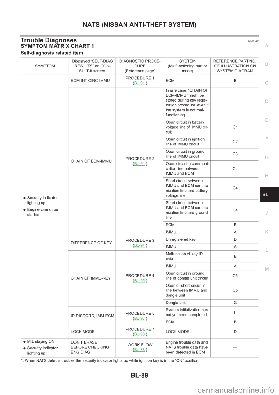
SYMPTOM MATRIX CHART 1
Self-diagnosis related item
*: When NATS detects trouble, the security indicator lights up while ignition key is in the “ON” position. SYMPTOMDisplayed “SELF-DIAG
RESULTS” on CON-
SULT-II screen.DIAGNOSTIC PROCE-
DURE
(Reference page)SYSTEM
(Malfunctioning part or
mode)REFERENCE PART NO.
OF ILLUSTRATION ON
SYSTEM DIAGRAM
●Security indicator
lighting up*
●Engine cannot be
startedECM INT CIRC-IMMUPROCEDURE 1
(BL-91
)ECM B
CHAIN OF ECM-IMMUPROCEDURE 2
(BL-91
)In rare case, “CHAIN OF
ECM-IMMU” might be
stored during key regis-
tration procedure, even if
the system is not mal-
functioning.—
Open circuit in battery
voltage line of IMMU cir-
cuitC1
Open circuit in ignition
line of IMMU circuitC2
Open circuit in ground
line of IMMU circuitC3
Open circuit in communi-
cation line between
IMMU and ECMC4
Short circuit between
IMMU and ECM commu-
nication line and battery
voltage lineC4
Short circuit between
IMMU and ECM commu-
nication line and ground
lineC4
ECM B
IMMU A
DIFFERENCE OF KEYPROCEDURE 3
(BL-94
)Unregistered key D
IMMU A
CHAIN OF IMMU-KEYPROCEDURE 4
(BL-95
)Malfunction of key ID
chipE
IMMU A
Open circuit in ground
line of dongle unit circuitC6
Open or short circuit in
line between IMMU and
dongle unitC5
Dongle unit G
ID DISCORD, IMM-ECMPROCEDURE 5
(BL-96
)System initialization has
not yet been completed.F
ECM B
LOCK MODEPROCEDURE 7
(BL-98
)LOCK MODE D
●MIL staying ON
●Security indicator
lighting up*DON'T ERASE
BEFORE CHECKING
ENG DIAGWORK FLOW
(BL-88 )Engine trouble data and
NATS trouble data have
been detected in ECM—
Page 3142 of 3833
BL-90
NATS (NISSAN ANTI-THEFT SYSTEM)
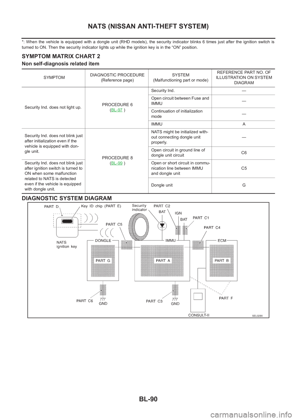
*: When the vehicle is equipped with a dongle unit (RHD models), the security indicator blinks 6 times just after the ignition switch is
turned to ON. Then the security indicator lights up while the ignition key is in the “ON” position.
SYMPTOM MATRIX CHART 2
Non self-diagnosis related item
DIAGNOSTIC SYSTEM DIAGRAM
SYMPTOMDIAGNOSTIC PROCEDURE
(Reference page)SYSTEM
(Malfunctioning part or mode)REFERENCE PART NO. OF
ILLUSTRATION ON SYSTEM
DIAGRAM
Security Ind. does not light up.PROCEDURE 6
(BL-97
)Security Ind. —
Open circuit between Fuse and
IMMU—
Continuation of initialization
mode—
IMMU A
Security Ind. does not blink just
after initialization even if the
vehicle is equipped with don-
gle unit.
PROCEDURE 8
(BL-99
)NATS might be initialized with-
out connecting dongle unit
properly.—
Open circuit in ground line of
dongle unit circuitC6
Security Ind. does not blink just
after ignition switch is turned to
ON when some malfunction
related to NATS is detected
even if the vehicle is equipped
with dongle unit.Open or short circuit in commu-
nication line between IMMU
and dongle unitC5
Dongle unit G
SEL028X
Page 3149 of 3833
NATS (NISSAN ANTI-THEFT SYSTEM)
BL-97
C
D
E
F
G
H
J
K
L
MA
B
BL
Diagnostic Procedure 6EIS001TC
“SECURITY INDICATOR LAMP DOES NOT LIGHT UP”
1.CHECK FUSE
Check 10A fuse [No. 28, located in the fuse block (J/B)].
Is 10A fuse OK?
Ye s > > G O T O 2
No >> Replace fuse.
2.CHECK SECURITY INDICATOR LAMP
1. Install 10A fuse.
2. Perform initialization with CONSULT-II.
For initialization, refer to “CONSULT-II Operation Manual NATS”.
3. Turn ignition switch OFF.
4. Start engine and turn ignition switch OFF.
5. Check the security indicator lamp lighting.
Security indicator lamp should be light up.
OK or NG
OK >> INSPECTION END
NG >> GO TO 3
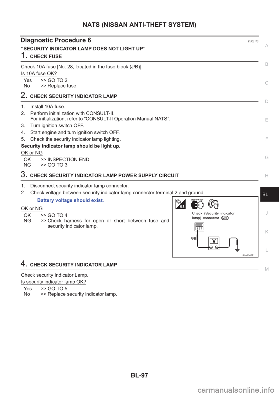
3.CHECK SECURITY INDICATOR LAMP POWER SUPPLY CIRCUIT
1. Disconnect security indicator lamp connector.
2. Check voltage between security indicator lamp connector terminal 2 and ground.
OK or NG
OK >> GO TO 4
NG >> Check harness for open or short between fuse and
security indicator lamp.
4.CHECK SECURITY INDICATOR LAMP
Check security Indicator Lamp.
Is security indicator lamp OK?
Ye s > > G O T O 5
No >> Replace security indicator lamp.Battery voltage should exist.
SIIA1243E