2001 NISSAN X-TRAIL light
[x] Cancel search: lightPage 2637 of 3833
TRANSFER ASSEMBLY
TF-27
C
E
F
G
H
I
J
K
L
MA
B
TF
Adapter case
1. Select the adjusting shim on the gear ring bearing.
●TF-23, "SELECTIONG ADJUSTING SHIMS".
2. Install the oil gutter.
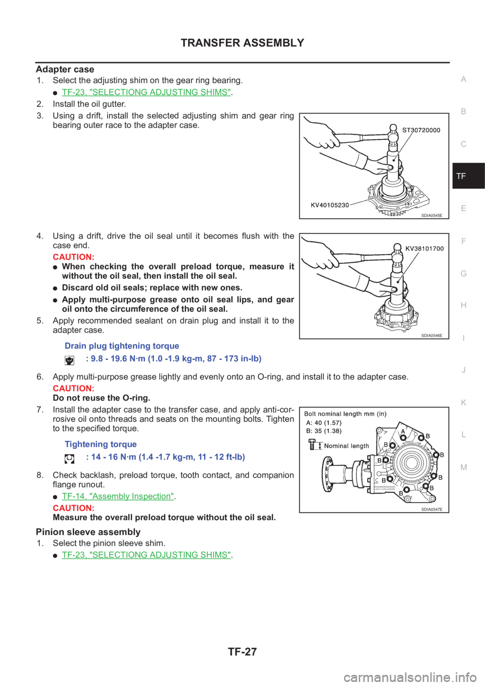
3. Using a drift, install the selected adjusting shim and gear ring
bearing outer race to the adapter case.
4. Using a drift, drive the oil seal until it becomes flush with the
case end.
CAUTION:
●When checking the overall preload torque, measure it
without the oil seal, then install the oil seal.
●Discard old oil seals; replace with new ones.
●Apply multi-purpose grease onto oil seal lips, and gear
oil onto the circumference of the oil seal.
5. Apply recommended sealant on drain plug and install it to the
adapter case.
6. Apply multi-purpose grease lightly and evenly onto an O-ring, and install it to the adapter case.
CAUTION:
Do not reuse the O-ring.
7. Install the adapter case to the transfer case, and apply anti-cor-
rosive oil onto threads and seats on the mounting bolts. Tighten
to the specified torque.
8. Check backlash, preload torque, tooth contact, and companion
flange runout.
●TF-14, "Assembly Inspection".
CAUTION:
Measure the overall preload torque without the oil seal.
Pinion sleeve assembly
1. Select the pinion sleeve shim.
●TF-23, "SELECTIONG ADJUSTING SHIMS".
SDIA0545E
Drain plug tightening torque
: 9.8 - 19.6 N·m (1.0 -1.9 kg-m, 87 - 173 in-lb)
Tightening torque
: 14 - 16 N·m (1.4 -1.7 kg-m, 11 - 12 ft-lb)
SDIA0546E
SDIA0547E
Page 2639 of 3833
TRANSFER ASSEMBLY
TF-29
C
E
F
G
H
I
J
K
L
MA
B
TF
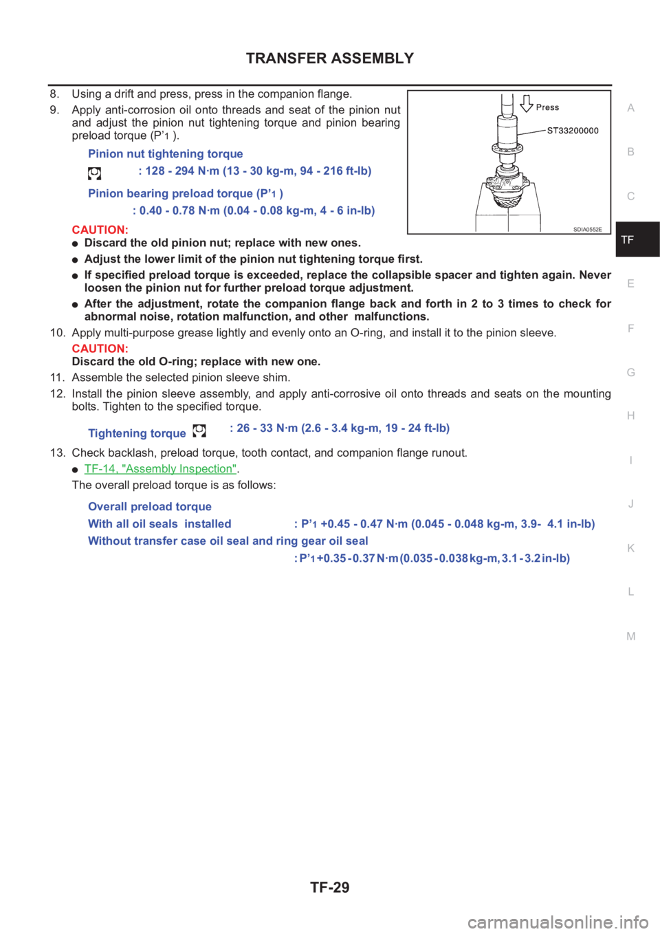
8. Using a drift and press, press in the companion flange.
9. Apply anti-corrosion oil onto threads and seat of the pinion nut
and adjust the pinion nut tightening torque and pinion bearing
preload torque (P’
1 ).
CAUTION:
●Discard the old pinion nut; replace with new ones.
●Adjust the lower limit of the pinion nut tightening torque first.
●If specified preload torque is exceeded, replace the collapsible spacer and tighten again. Never
loosen the pinion nut for further preload torque adjustment.
●After the adjustment, rotate the companion flange back and forth in 2 to 3 times to check for
abnormal noise, rotation malfunction, and other malfunctions.
10. Apply multi-purpose grease lightly and evenly onto an O-ring, and install it to the pinion sleeve.
CAUTION:
Discard the old O-ring; replace with new one.
11. Assemble the selected pinion sleeve shim.
12. Install the pinion sleeve assembly, and apply anti-corrosive oil onto threads and seats on the mounting
bolts. Tighten to the specified torque.
13. Check backlash, preload torque, tooth contact, and companion flange runout.
●TF-14, "Assembly Inspection".
The overall preload torque is as follows:Pinion nut tightening torque
: 128 - 294 N·m (13 - 30 kg-m, 94 - 216 ft-lb)
Pinion bearing preload torque (P’
1 )
: 0.40 - 0.78 N·m (0.04 - 0.08 kg-m, 4 - 6 in-lb)
Tightening torque : 26 - 33 N·m (2.6 - 3.4 kg-m, 19 - 24 ft-lb)
Overall preload torque
With all oil seals installed : P’
1 +0.45 - 0.47 N·m (0.045 - 0.048 kg-m, 3.9- 4.1 in-lb)
Without transfer case oil seal and ring gear oil seal
: P’
1 + 0 . 3 5 - 0 . 3 7 N · m ( 0 . 0 3 5 - 0 . 0 3 8 k g - m , 3 . 1 - 3 . 2 i n - l b )
SDIA0552E
Page 2652 of 3833
TF-42
TROUBLE DIAGNOSIS
NOTE:
1. Light tight-corner braking symptom may occur depending on driving conditions in AUTO mode. This is not
malfunction.
2. Heavy tight-corner braking symptom occurs when vehicle is driven in the following conditions: LOCK
mode, steering wheel is turned fully to either sides, and accelerator pedal was depressed.
3. When the difference of revolution speed between the front and the rear wheels is large, the 4WD mode
does not change to other mode.this is not a malfunction.
4WD control unit input/output signal standardEDS000H9
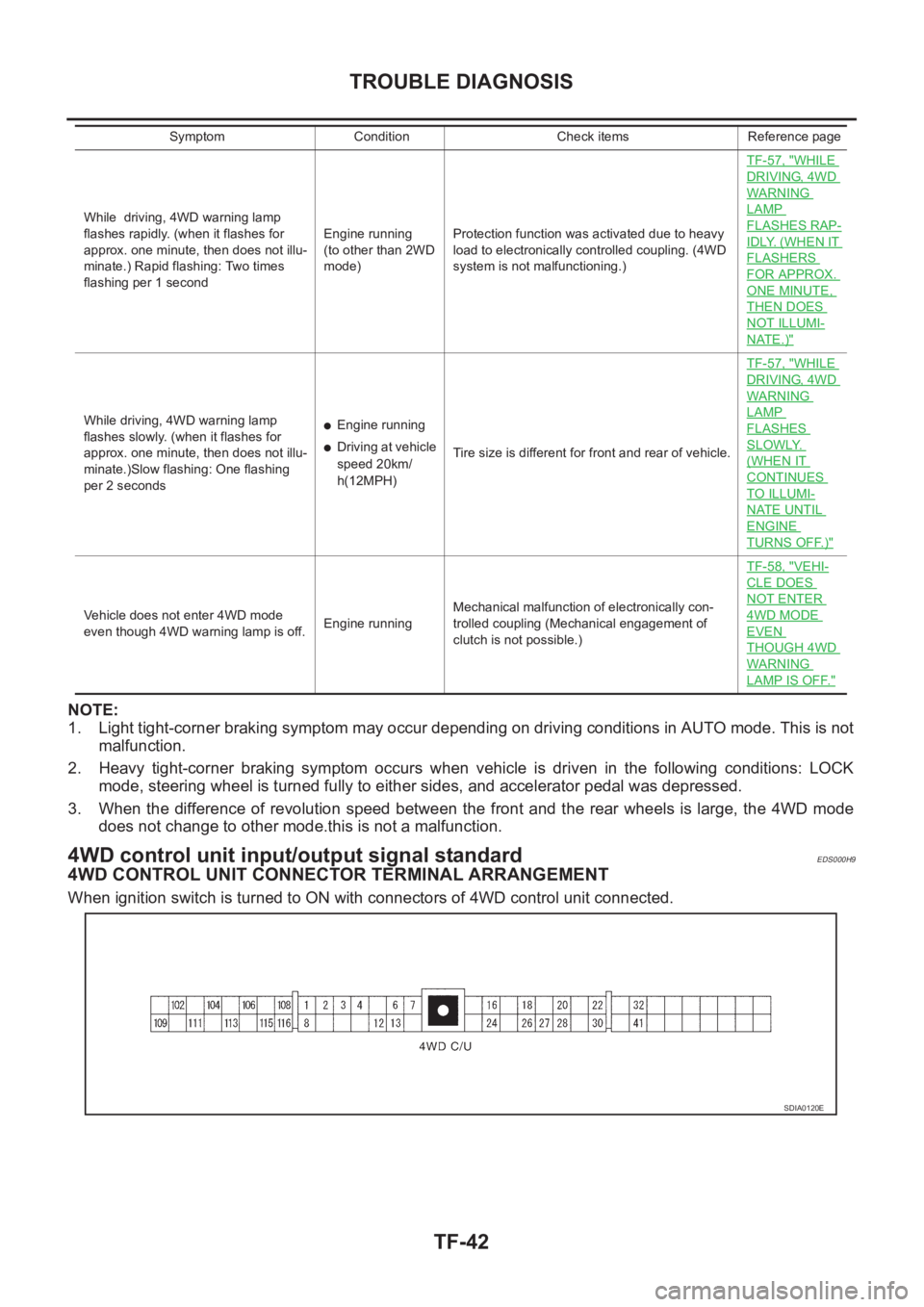
4WD CONTROL UNIT CONNECTOR TERMINAL ARRANGEMENT
When ignition switch is turned to ON with connectors of 4WD control unit connected.
While driving, 4WD warning lamp
flashes rapidly. (when it flashes for
approx. one minute, then does not illu-
minate.) Rapid flashing: Two times
flashing per 1 secondEngine running
(to other than 2WD
mode)Protection function was activated due to heavy
load to electronically controlled coupling. (4WD
system is not malfunctioning.)TF-57, "
WHILE
DRIVING, 4WD
WARNING
LAMP
FLASHES RAP-
IDLY. (WHEN IT
FLASHERS
FOR APPROX.
ONE MINUTE,
THEN DOES
NOT ILLUMI-
NATE.)"
While driving, 4WD warning lamp
flashes slowly. (when it flashes for
approx. one minute, then does not illu-
minate.)Slow flashing: One flashing
per 2 seconds●Engine running
●Driving at vehicle
speed 20km/
h(12MPH)Tire size is different for front and rear of vehicle.TF-57, "
WHILE
DRIVING, 4WD
WARNING
LAMP
FLASHES
SLOWLY.
(WHEN IT
CONTINUES
TO ILLUMI-
NATE UNTIL
ENGINE
TURNS OFF.)"
Vehicle does not enter 4WD mode
even though 4WD warning lamp is off.Engine runningMechanical malfunction of electronically con-
trolled coupling (Mechanical engagement of
clutch is not possible.)TF-58, "
VEHI-
CLE DOES
NOT ENTER
4WD MODE
EVEN
THOUGH 4WD
WARNING
LAMP IS OFF."
Symptom Condition Check items Reference page
SDIA0120E
Page 2659 of 3833
TROUBLE DIAGNOSIS
TF-49
C
E
F
G
H
I
J
K
L
MA
B
TF
4WD solenoid valve
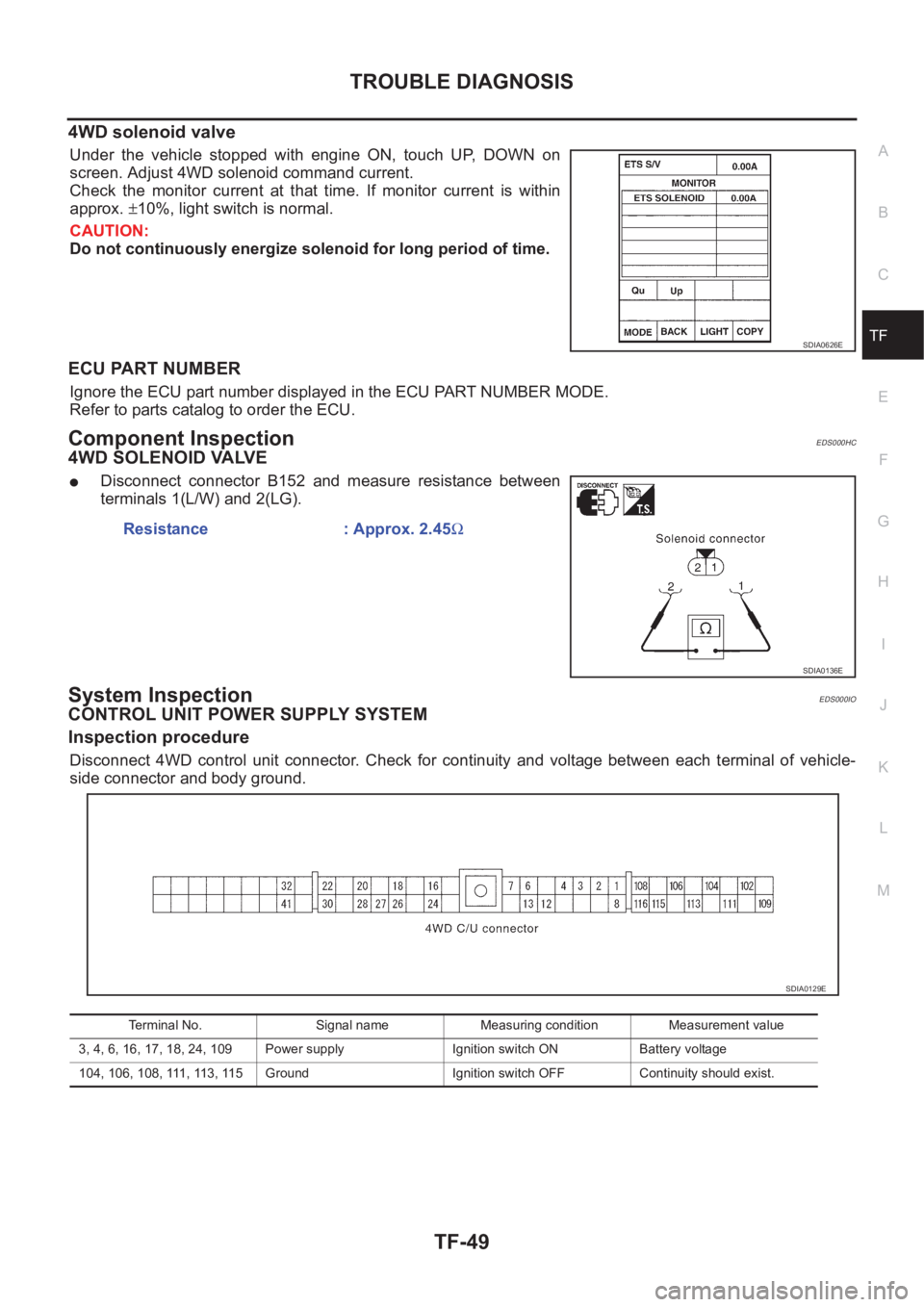
Under the vehicle stopped with engine ON, touch UP, DOWN on
screen. Adjust 4WD solenoid command current.
Check the monitor current at that time. If monitor current is within
approx. ±10%, light switch is normal.
CAUTION:
Do not continuously energize solenoid for long period of time.
ECU PART NUMBER
Ignore the ECU part number displayed in the ECU PART NUMBER MODE.
Refer to parts catalog to order the ECU.
Component InspectionEDS000HC
4WD SOLENOID VALVE
●Disconnect connector B152 and measure resistance between
terminals 1(L/W) and 2(LG).
System InspectionEDS000IO
CONTROL UNIT POWER SUPPLY SYSTEM
Inspection procedure
Disconnect 4WD control unit connector. Check for continuity and voltage between each terminal of vehicle-
side connector and body ground.
SDIA0626E
Resistance : Approx. 2.45Ω
SDIA0136E
Terminal No. Signal name Measuring condition Measurement value
3, 4, 6, 16, 17, 18, 24, 109 Power supply Ignition switch ON Battery voltage
104, 106, 108, 111, 113, 115 Ground Ignition switch OFF Continuity should exist.
SDIA0129E
Page 2667 of 3833
TROUBLE DIAGNOSIS
TF-57
C
E
F
G
H
I
J
K
L
MA
B
TF
3.INSPECTION USING 4WD MODE CHANGE-OVER SWITCH
●On data monitor screen of the CONSULT-II, check 4WD mode switch.
●Check if the display changes from ## to 2WD mode when the 2WD switch is pressed.
●Check if the display changes from ## to AUTO mode when the AUTO switch is pressed.
●Check if the display changes from ## to LOCK mode when the LOCK switch is pressed.
OK or NG
OK >> No malfunction detected.
NG >>
●Not in AUTO mode. (In 2WD or LOCK mode)
Countermeasure: Slightly depress the accelerator pedal and check that the operation mode
changes to LOCK mode.
●Check circuit between 4WD mode switch harness connector M39 terminal No.1 (BR) and
4WD control unit harness connector E122 terminal No. 27 (BR).
(AUTO mode is not available because a malfunction is present in the 2WD mode harness.)
NOTICE:
Mechanism of 4WD mode change-over.
●2WD mode: Operation changes to 2WD mode when 4WD control unit harness connector E122
terminal No. 27 (BR) is shorted to ground.
●AUTO mode: Operation changes to AUTO mode when 4WD control unit harness connector
E122 terminals No. 27 (BR) and No. 26 (L) is shorted to ground.
●LOCK mode: Operation changes to LOCK mode when 4WD control unit harness connector
E122 terminal No. 26 (L) is shorted to ground.
4WD MODES CANNOT BE SWITCHED AFTER ENGINE IS STARTED
1.INSPECTION USING 4WD MODE CHANGE-OVER SWITCH
●Drive modes cannot be switched after the engine is started.
●On data monitor screen of the CONSULT-II, check 4WD mode switch.
●Check if the display changes from ## to 2WD mode when the 2WD switch is pressed.
●Check if the display changes from ## to AUTO mode when the AUTO switch is pressed.
●Check if the display changes from ## to LOCK mode when the LOCK switch is pressed.
OK or NG
OK >> No malfunction detected.
NG >>
●CONSULT-II display does not change from ## when the 2WD switch is pressed. Check harness
of the 2WD switch.
●CONSULT-II display does not change from ## when the AUTO switch is pressed. Check har-
ness of the 2WD switch and LOCK switch.
●CONSULT-II display does not change from ## when the LOCK switch is pressed. Check har-
ness of the LOCK switch.
●Perform 4WD mode change-over switch inspection.
WHILE DRIVING, 4WD WARNING LAMP FLASHES RAPIDLY. (WHEN IT FLASHERS FOR
APPROX. ONE MINUTE, THEN DOES NOT ILLUMINATE.)
●While driving, 4WD warning lamp flashes rapidly. (when it flashes for approx. one minute, then does not
illuminate.)
Rapid flashing: 2 times/second
This phenomenon protects drivetrain parts when a heavy load is applied to the electronically controlled
coupling and multiple disc clutch temperature increases. It is not a malfunction.
When the difference of diameters by or with the front and rear wheel with AUTO mode the shift switch
occasionally changes to LOCK mode automatically. This is not a malfunction.
When the difference of revolution speed between the front and rear wheel with AUTO mode, the shift
switch occasionally changes to LOCK mode automatically. This is not a malfunction.
WHILE DRIVING, 4WD WARNING LAMP FLASHES SLOWLY. (WHEN IT CONTINUES TO ILLU-
MINATE UNTIL ENGINE TURNS OFF.)
1. Check using the data monitor function of the CONSULT-II.
Page 2714 of 3833
FSU-8
COIL SPRING AND SHOCK ABSORBER
COIL SPRING AND SHOCK ABSORBER
PFP:54302
Removal and InstallationEES00074
REMOVAL
1. Remove tires. Remove brake caliper and hung it aside.
CAUTION:
Avoid depressing brake pedal with brake caliper removed.
2. Remove electrical wires of ABS wheel speed sensor from strut.
3. Remove brake hose lock plate.
4. Remove mounting bolts and nuts securing steering knuckle to strut.
5. Remove mounting nuts on upper mounting plate and remove upper mounting plate and strut from vehicle.
INSTALLATION
●Refer to FSU-5, "Components" in “Front Suspension Assembly” for tightening torque. Tighten in the
reverse order of removal.
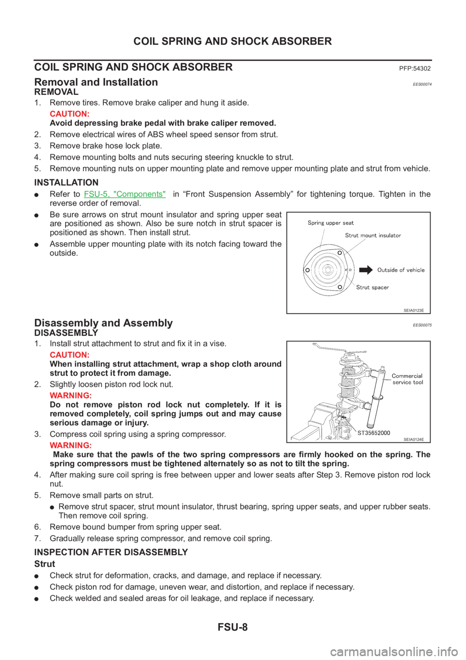
●Be sure arrows on strut mount insulator and spring upper seat
are positioned as shown. Also be sure notch in strut spacer is
positioned as shown. Then install strut.
●Assemble upper mounting plate with its notch facing toward the
outside.
Disassembly and AssemblyEES00075
DISASSEMBLY
1. Install strut attachment to strut and fix it in a vise.
CAUTION:
When installing strut attachment, wrap a shop cloth around
strut to protect it from damage.
2. Slightly loosen piston rod lock nut.
WARNING:
Do not remove piston rod lock nut completely. If it is
removed completely, coil spring jumps out and may cause
serious damage or injury.
3. Compress coil spring using a spring compressor.
WARNING:
Make sure that the pawls of the two spring compressors are firmly hooked on the spring. The
spring compressors must be tightened alternately so as not to tilt the spring.
4. After making sure coil spring is free between upper and lower seats after Step 3. Remove piston rod lock
nut.
5. Remove small parts on strut.
●Remove strut spacer, strut mount insulator, thrust bearing, spring upper seats, and upper rubber seats.
Then remove coil spring.
6. Remove bound bumper from spring upper seat.
7. Gradually release spring compressor, and remove coil spring.
INSPECTION AFTER DISASSEMBLY
Strut
●Check strut for deformation, cracks, and damage, and replace if necessary.
●Check piston rod for damage, uneven wear, and distortion, and replace if necessary.
●Check welded and sealed areas for oil leakage, and replace if necessary.
SEIA0123E
SEIA0124E
Page 2716 of 3833
FSU-10
TRANSVERSE LINK
TRANSVERSE LINK
PFP:54500
Removal and InstallationEES00076
REMOVAL
1. Remove steering knuckle from transverse link. Refer toFAX-7, "REMOVAL" .
2. Remove mounting nuts and washers on lower portion of stabilizer connecting rod.
3. Slightly loosen transverse link mounting bolts.
4. Remove transverse link mounting bolts and nuts, and remove transverse link from suspension member.
INSPECTION AFTER REMOVAL
Visual Inspection
Check transverse link and bushing for deformation, cracks, and other damage. Replace the entire transverse
link assembly if cracks, deformation or any other damage is found.
Ball Joint Inspection
CAUTION:
Before measurement, move the ball joint at least ten times by hand to check for smooth movement.
Swing Torque Inspection
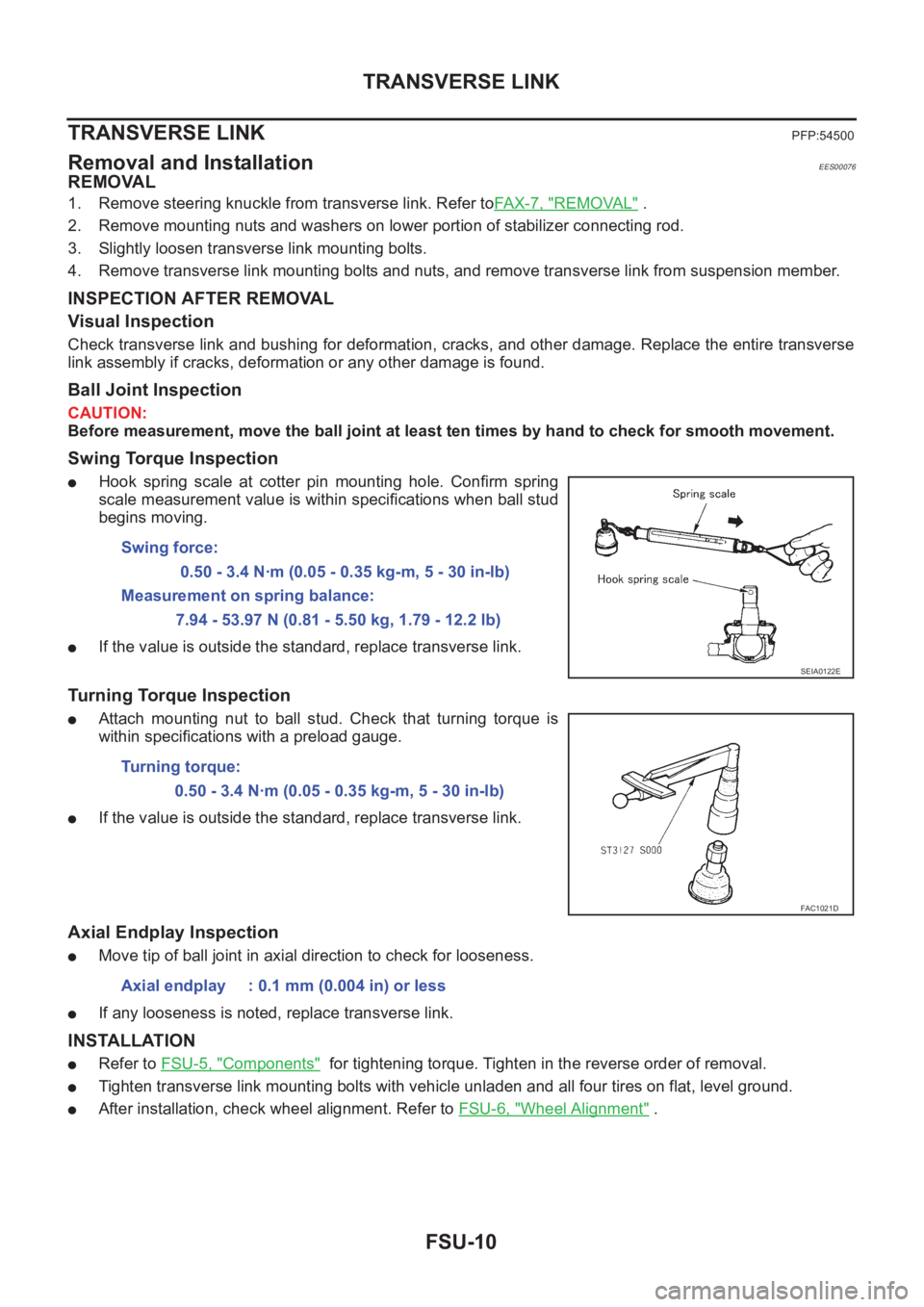
●Hook spring scale at cotter pin mounting hole. Confirm spring
scale measurement value is within specifications when ball stud
begins moving.
●If the value is outside the standard, replace transverse link.
Turning Torque Inspection
●Attach mounting nut to ball stud. Check that turning torque is
within specifications with a preload gauge.
●If the value is outside the standard, replace transverse link.
Axial Endplay Inspection
●Move tip of ball joint in axial direction to check for looseness.
●If any looseness is noted, replace transverse link.
INSTALLATION
●Refer to FSU-5, "Components" for tightening torque. Tighten in the reverse order of removal.
●Tighten transverse link mounting bolts with vehicle unladen and all four tires on flat, level ground.
●After installation, check wheel alignment. Refer to FSU-6, "Wheel Alignment" . Swing force:
0.50 - 3.4 N·m (0.05 - 0.35 kg-m, 5 - 30 in-lb)
Measurement on spring balance:
7.94 - 53.97 N (0.81 - 5.50 kg, 1.79 - 12.2 lb)
SEIA0122E
Turning torque:
0.50 - 3.4 N·m (0.05 - 0.35 kg-m, 5 - 30 in-lb)
FAC1021D
Axial endplay : 0.1 mm (0.004 in) or less
Page 2728 of 3833
RSU-8
COIL SPRING AND STRUT
COIL SPRING AND STRUT
PFP:55302
Removal and InstallationEES0007H
REMOVAL
1. Remove tires.
2. Remove brake hose lock plate and remove brake hose from strut.
3. Remove mounting nuts and washers on upper portion of stabilizer connecting rod.
4. Remove strut-to-axle housing mounting bolts and nuts.
5. Remove luggage side lower finisher in luggage compartment. Remove mounting nuts on strut spacer.
Then remove strut from vehicle.
INSTALLATION
●Refer to RSU-5, "Components" for tightening torque. Install in the reverse order of removal.
Disassembly and AssemblyEES0007I
DISASSEMBLY
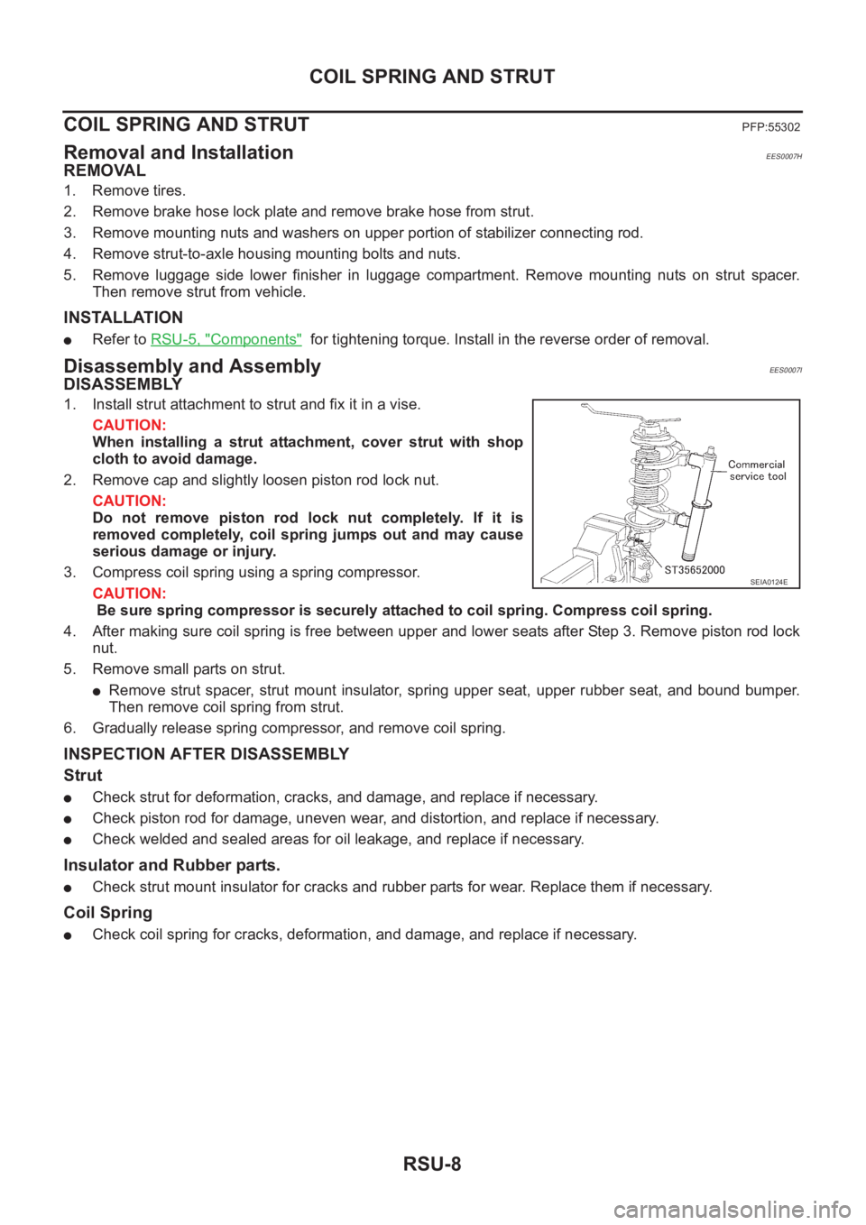
1. Install strut attachment to strut and fix it in a vise.
CAUTION:
When installing a strut attachment, cover strut with shop
cloth to avoid damage.
2. Remove cap and slightly loosen piston rod lock nut.
CAUTION:
Do not remove piston rod lock nut completely. If it is
removed completely, coil spring jumps out and may cause
serious damage or injury.
3. Compress coil spring using a spring compressor.
CAUTION:
Be sure spring compressor is securely attached to coil spring. Compress coil spring.
4. After making sure coil spring is free between upper and lower seats after Step 3. Remove piston rod lock
nut.
5. Remove small parts on strut.
●Remove strut spacer, strut mount insulator, spring upper seat, upper rubber seat, and bound bumper.
Then remove coil spring from strut.
6. Gradually release spring compressor, and remove coil spring.
INSPECTION AFTER DISASSEMBLY
Strut
●Check strut for deformation, cracks, and damage, and replace if necessary.
●Check piston rod for damage, uneven wear, and distortion, and replace if necessary.
●Check welded and sealed areas for oil leakage, and replace if necessary.
Insulator and Rubber parts.
●Check strut mount insulator for cracks and rubber parts for wear. Replace them if necessary.
Coil Spring
●Check coil spring for cracks, deformation, and damage, and replace if necessary.
SEIA0124E