2001 NISSAN X-TRAIL valve lash
[x] Cancel search: valve lashPage 48 of 3833

GI-46
TERMINOLOGY
Exhaust gas recirculation control-BPT
valveEGRC-BPT valve BPT valve
Exhaust gas recirculation control-solenoid
valveEGRC-solenoid valve EGR control solenoid valve
Exhaust gas recirculation temperature sen-
sor
EGRT sensor Exhaust gas temperature sensor
EGR temperature sensor
Flash electrically erasable programmable
read only memoryFEEPROM ***
Flash erasable programmable read only
memoryFEPROM ***
Flexible fuel sensor FFS ***
Flexible fuel system FF system ***
Fuel pressure regulator *** Pressure regulator
Fuel pressure regulator control solenoid
valve*** PRVR control solenoid valve
Fuel trim FT ***
Heated Oxygen sensor HO2S Exhaust gas sensor
Idle air control system IAC system Idle speed control
Idle air control valve-air regulator IACV-air regulator Air regulator
Idle air control valve-auxiliary air control
valveIACV-AAC valve Auxiliary air control (AAC) valve
Idle air control valve-FICD solenoid valve IACV-FICD solenoid valve FICD solenoid valve
Idle air control valve-idle up control sole-
noid valveIACV-idle up control solenoid valve Idle up control solenoid valve
Idle speed control-FI pot ISC-FI pot FI pot
Idle speed control system ISC system ***
Ignition control IC ***
Ignition control module ICM ***
Indirect fuel injection system IFI system ***
Intake air IA Air
Intake air temperature sensor IAT sensor Air temperature sensor
Knock *** Detonation
Knock sensor KS Detonation sensor
Malfunction indicator lamp MIL Check engine light
Manifold absolute pressure MAP ***
Manifold absolute pressure sensor MAPS ***
Manifold differential pressure MDP ***
Manifold differential pressure sensor MDPS ***
Manifold surface temperature MST ***
Manifold surface temperature sensor MSTS ***
Manifold vacuum zone MVZ ***
Manifold vacuum zone sensor MVZS ***
Mass air flow sensor MAFS Air flow meter
Mixture control solenoid valve MC solenoid valve Air-fuel ratio control solenoid valve
Multiport fuel injection System MFI system Fuel injection controlNEW TERMNEW ACRONYM /
ABBREVIATIONOLD TERM
Page 97 of 3833
![NISSAN X-TRAIL 2001 Service Repair Manual CAMSHAFT
EM-47
[QR]
C
D
E
F
G
H
I
J
K
L
MA
EM
4. Remove Intake valve timing control cover.
a. Loosen bolts in reverse order shown in the figure.
b. Disconnect intake valve timing control solenoid NISSAN X-TRAIL 2001 Service Repair Manual CAMSHAFT
EM-47
[QR]
C
D
E
F
G
H
I
J
K
L
MA
EM
4. Remove Intake valve timing control cover.
a. Loosen bolts in reverse order shown in the figure.
b. Disconnect intake valve timing control solenoid](/manual-img/5/57405/w960_57405-96.png)
CAMSHAFT
EM-47
[QR]
C
D
E
F
G
H
I
J
K
L
MA
EM
4. Remove Intake valve timing control cover.
a. Loosen bolts in reverse order shown in the figure.
b. Disconnect intake valve timing control solenoid valve harness
connector, and remove intake valve timing control solenoid
valve.
c. Remove the cover using Tool (Seal cutter).
5. Set No. 1 cylinder at TDC on its compression stroke with the fol-
lowing procedure.
a. Open splash cover on RH undercover.
b. Rotate crankshaft pulley clockwise, and align mating marks for
TDC with timing indicator on front cover.
c. At the same time, make sure that the mating marks on camshaft
sprockets are located as shown in the figure.
●If not, rotate crankshaft pulley one more turn to line up the
mating marks to the positions in the figure.
6. Pull chain guide between camshaft sprockets out through front
cover.
7. Remove camshaft sprockets with the following procedure.
a. Line up the mating marks on camshaft sprockets, and paint an
indelible mating mark on timing chain link plate.
b. Push in tensioner plunger. Insert a stopper pin into hole on ten-
sioner body to fix chain tensioner and remove it.
●Use wire of 0.5 mm (0.02 in) in diameter as a stopper pin.
KBIA0085E
KBIA0190E
KBIA0115E
KBIA0048E
Page 103 of 3833
![NISSAN X-TRAIL 2001 Service Repair Manual CAMSHAFT
EM-53
[QR]
C
D
E
F
G
H
I
J
K
L
MA
EM
Valve Lifter Hole Diameter
Using inside micrometer, measure diameter of valve lifter hole of cyl-
inder head.
Calculation of Valve Lifter Clearance
(Valve NISSAN X-TRAIL 2001 Service Repair Manual CAMSHAFT
EM-53
[QR]
C
D
E
F
G
H
I
J
K
L
MA
EM
Valve Lifter Hole Diameter
Using inside micrometer, measure diameter of valve lifter hole of cyl-
inder head.
Calculation of Valve Lifter Clearance
(Valve](/manual-img/5/57405/w960_57405-102.png)
CAMSHAFT
EM-53
[QR]
C
D
E
F
G
H
I
J
K
L
MA
EM
Valve Lifter Hole Diameter
Using inside micrometer, measure diameter of valve lifter hole of cyl-
inder head.
Calculation of Valve Lifter Clearance
(Valve lifter clearance) = (hole diameter of valve lifter) – (outer diam-
eter of valve lifter).
●When out of specified range, referring to each specification of
outer and inner diameter, replace either or both valve lifter and
cylinder head.
Va l v e C l e a r a n c eEBS00LS3
INSPECTION
Perform inspection as follows after removal, installation or replacement of camshaft or valve-related parts, or if
there is unusual engine conditions due to changes in valve clearance over time (starting, idling, and/or noise).
1. Warm up engine. Then stop it.
2. Remove splash cover on RH undercover.
3. Remove rocker cover. Refer to EM-35, "
ROCKER COVER" .
4. Turn crankshaft pulley in normal direction (clockwise when
viewed from front) to align TDC identification notch (without
paint mark) with timing indicator.
5. At this time, check that the both intake and exhaust cam noses
of No. 1 cylinder face outside.
●If they do not face outside, turn crankshaft pulley once more.
6. By referring to the figure, measure valve clearances at locations
marked X as shown in the table below (locations indicated with
black arrow in figure) with a feeler gauge.
●No. 1 cylinder compression TDC.Standard: 34.000 - 34.021 mm (1.3386 - 1.3394 in)
Standard: 0.020 - 0.056 mm (0.0008 - 0.0022 in)
PBIC0043E
KBIA0190E
KBIA0400J
Measuring position No.1 CYL. No.2 CYL. No.3 CYL. No.4 CYL.
No.1 cylinder at
TDCINT X X
EXH X X
SBIA0261E
Page 106 of 3833
![NISSAN X-TRAIL 2001 Service Repair Manual EM-56
[QR]
OIL SEAL
OIL SEAL
PFP:12279
Removal and Installation of Valve Oil SealEBS00KNM
REMOVAL
1. Remove camshaft. Refer to EM-46, "CAMSHAFT" .
2. Remove valve lifter. Refer to EM-46, " NISSAN X-TRAIL 2001 Service Repair Manual EM-56
[QR]
OIL SEAL
OIL SEAL
PFP:12279
Removal and Installation of Valve Oil SealEBS00KNM
REMOVAL
1. Remove camshaft. Refer to EM-46, "CAMSHAFT" .
2. Remove valve lifter. Refer to EM-46, "](/manual-img/5/57405/w960_57405-105.png)
EM-56
[QR]
OIL SEAL
OIL SEAL
PFP:12279
Removal and Installation of Valve Oil SealEBS00KNM
REMOVAL
1. Remove camshaft. Refer to EM-46, "CAMSHAFT" .
2. Remove valve lifter. Refer to EM-46, "
CAMSHAFT" .
3. Rotate crankshaft, and set piston whose oil seal is to be
removed to top dead center. This prevents valve from dropping
inside cylinder.
CAUTION:
When rotating crankshaft, be careful to avoid scarring the
front cover with the timing chain.
4. Remove valve collet, valve spring retainer and valve spring with
SST. Refer to EM-59, "
CYLINDER HEAD" .
5. Remove valve oil seal with SST.
INSTALLATION
1. Apply new engine oil to valve oil seal joint surface and seal lip.
2. Press in valve oil seal to the position shown in the figure with
SST.
3. Install followings in the reverse order of removal.
Removal and Installation of Front Oil SealEBS00KNN
REMOVAL
1. Remove the parts listed below.
●Under cover (with splash cover).
●Drive belts. Refer to EM-12, "DRIVE BELTS" .
●Crank pulley. Refer to EM-37, "TIMING CHAIN" .
2. Remove front oil seal.
CAUTION:
Be careful not to damage front cover and crankshaft.
PBIC0277E
SEM093F
SBIA0270E
Page 2611 of 3833

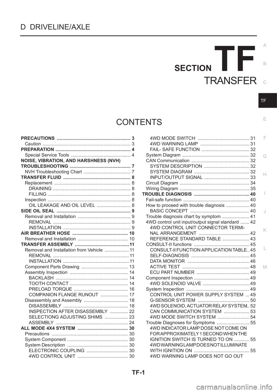
TF-1
TRANSFER
D DRIVELINE/AXLE
CONTENTS
C
E
F
G
H
I
J
K
L
M
SECTION
A
B
TF
TRANSFER
PRECAUTIONS .......................................................... 3
Caution ..................................................................... 3
PREPARATION ........................................................... 4
Special Service Tools ............................................... 4
NOISE, VIBRATION, AND HARSHNESS (NVH)
TROUBLESHOOTING ................................................ 7
NVH Troubleshooting Chart ..................................... 7
TRANSFER FLUID ..................................................... 8
Replacement ............................................................ 8
DRAINING ............................................................. 8
FILLING ................................................................. 8
Inspection ................................................................. 8
OIL LEAKAGE AND OIL LEVEL ........................... 8
SIDE OIL SEAL .......................................................... 9
Removal and Installation .......................................... 9
REMOVAL ............................................................. 9
INSTALLATION ..................................................... 9
AIR BREATHER HOSE ............................................ 10
Removal and Installation ........................................ 10
TRANSFER ASSEMBLY ...........................................11
Removal and Installation from Vehicle .................... 11
REMOVAL ............................................................ 11
INSTALLATION .................................................... 11
Component Parts Drawing ..................................... 13
Assembly Inspection .............................................. 14
BACKLASH ......................................................... 14
TOOTH CONTACT .............................................. 14
PRELOAD TORQUE ........................................... 16
COMPANION FLANGE RUNOUT ...................... 17
Disassembly and Assembly ................................... 18
DISASSEMBLY ................................................... 18
INSPECTION AFTER DISASSEMBLY ............... 22
SELECTIONG ADJUSTING SHIMS ................... 23
ASSEMBLY ......................................................... 24
ALL MODE 4X4 SYSTEM ........................................ 30
Precautions ............................................................ 30
System Component ................................................ 30
System Description ................................................ 30
ELECTRONIC COUPLING ................................. 30
4WD CONTROL UNIT ........................................ 304WD MODE SWITCH ......................................... 31
4WD WARNING LAMP ....................................... 31
FAIL- SAFE FUNCTION ...................................... 32
System Diagram ..................................................... 32
CAN Communication ...........................................
... 32
SYSTEM DESCRIPTION .................................... 32
SYSTEM DIAGRAM ............................................ 32
INPUT/OUTPUT SIGNAL .................................... 33
Circuit Diagram ....................................................... 34
Wiring Diagram ....................................................... 35
TROUBLE DIAGNOSIS ............................................ 40
Fail-safe function .................................................... 40
How to proceed with trouble diagnosis ................... 40
BASIC CONCEPT ............................................... 40
Trouble diagnosis chart by symptom ...................... 41
4WD control unit input/output signal standard ........ 42
4WD CONTROL UNIT CONNECTOR TERMI-
NAL ARRANGEMENT ........................................ 42
REFERENCE STANDARD TABLE ...................... 43
CONSULT-II functions ............................................ 45
CONSULT-II FUNCTION APPLICATION TABLE ... 45
SELF-DIAGNOSIS .............................................. 45
DATA MONITOR ................................................. 46
ACTIVE TEST ..................................................... 48
ECU PART NUMBER .......................................... 49
Component Inspection ............................................ 49
4WD SOLENOID VALVE ..................................... 49
System Inspection .................................................. 49
CONTROL UNIT POWER SUPPLY SYSTEM .... 49
G-SENSOR SYSTEM ......................................... 50
4WD SOLENOID, ACTUATOR RELAY SYSTEM ... 52
CAN COMMUNICATION SYSTEM ..................... 53
4WD MODE SWITCH SYSTEM .......................... 54
Trouble Diagnoses for Symptoms .......................... 55
4WD INDICATOR LAMP DOSE NOT COME ON
FOR APPROXIMATELY 1 SECOND WHEN THE
IGNITION SWITCH IS TURNED TO ON ............. 55
4WD WARNING LAMP DOES NOT ILLUMINATE
WITH IGNITION ON ............................................ 55
4WD WARNING LAMP DOES NOT GO OUT
Page 2668 of 3833

TF-58
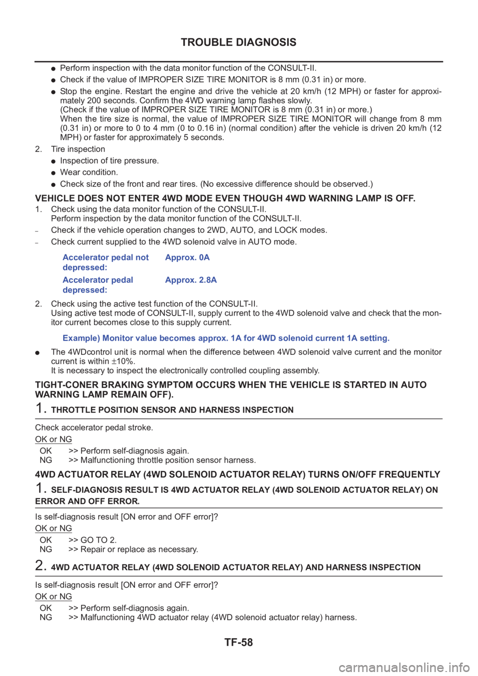
TROUBLE DIAGNOSIS
●Perform inspection with the data monitor function of the CONSULT- I I .
●Check if the value of IMPROPER SIZE TIRE MONITOR is 8 mm (0.31 in) or more.
●Stop the engine. Restart the engine and drive the vehicle at 20 km/h (12 MPH) or faster for approxi-
mately 200 seconds. Confirm the 4WD warning lamp flashes slowly.
(Check if the value of IMPROPER SIZE TIRE MONITOR is 8 mm (0.31 in) or more.)
When the tire size is normal, the value of IMPROPER SIZE TIRE MONITOR will change from 8 mm
(0.31 in) or more to 0 to 4 mm (0 to 0.16 in) (normal condition) after the vehicle is driven 20 km/h (12
MPH) or faster for approximately 5 seconds.
2. Tire inspection
●Inspection of tire pressure.
●Wear condition.
●Check size of the front and rear tires. (No excessive difference should be observed.)
VEHICLE DOES NOT ENTER 4WD MODE EVEN THOUGH 4WD WARNING LAMP IS OFF.
1. Check using the data monitor function of the CONSULT-II.
Perform inspection by the data monitor function of the CONSULT-II.
–Check if the vehicle operation changes to 2WD, AUTO, and LOCK modes.
–Check current supplied to the 4WD solenoid valve in AUTO mode.
2. Check using the active test function of the CONSULT-II.
Using active test mode of CONSULT-II, supply current to the 4WD solenoid valve and check that the mon-
itor current becomes close to this supply current.
●The 4WDcontrol unit is normal when the difference between 4WD solenoid valve current and the monitor
current is within ±10%.
It is necessary to inspect the electronically controlled coupling assembly.
TIGHT-CONER BRAKING SYMPTOM OCCURS WHEN THE VEHICLE IS STARTED IN AUTO
WARNING LAMP REMAIN OFF).
1. THROTTLE POSITION SENSOR AND HARNESS INSPECTION
Check accelerator pedal stroke.
OK or NG
OK >> Perform self-diagnosis again.
NG >> Malfunctioning throttle position sensor harness.
4WD ACTUATOR RELAY (4WD SOLENOID ACTUATOR RELAY) TURNS ON/OFF FREQUENTLY
1. SELF-DIAGNOSIS RESULT IS 4WD ACTUATOR RELAY (4WD SOLENOID ACTUATOR RELAY) ON
ERROR AND OFF ERROR.
Is self-diagnosis result [ON error and OFF error]?
OK or NG
OK >> GO TO 2.
NG >> Repair or replace as necessary.
2. 4WD ACTUATOR RELAY (4WD SOLENOID ACTUATOR RELAY) AND HARNESS INSPECTION
Is self-diagnosis result [ON error and OFF error]?
OK or NG
OK >> Perform self-diagnosis again.
NG >> Malfunctioning 4WD actuator relay (4WD solenoid actuator relay) harness. Accelerator pedal not
depressed:Approx. 0A
Accelerator pedal
depressed:Approx. 2.8A
Example) Monitor value becomes approx. 1A for 4WD solenoid current 1A setting.
Page 2785 of 3833

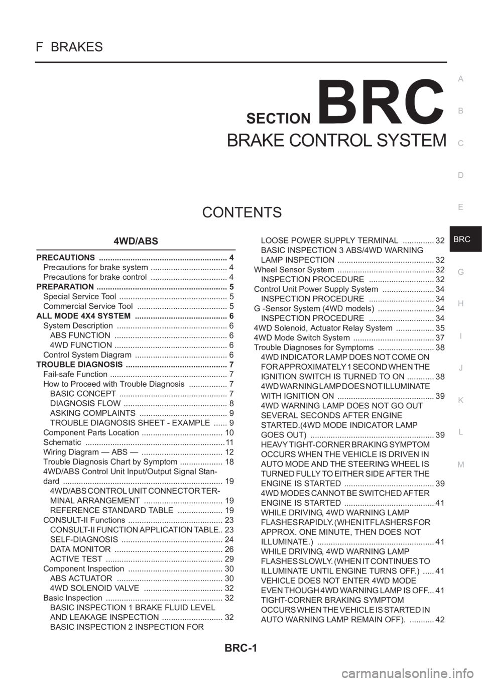
BRC-1
BRAKE CONTROL SYSTEM
F BRAKES
CONTENTS
C
D
E
G
H
I
J
K
L
M
SECTION
A
B
BRC
BRAKE CONTROL SYSTEM
4WD/ABS
PRECAUTIONS .......................................................... 4
Precautions for brake system ................................... 4
Precautions for brake control ................................... 4
PREPARATION ........................................................... 5
Special Service Tool ................................................. 5
Commercial Service Tool ......................................... 5
ALL MODE 4X4 SYSTEM .......................................... 6
System Description .................................................. 6
ABS FUNCTION ................................................... 6
4WD FUNCTION ................................................... 6
Control System Diagram .......................................... 6
TROUBLE DIAGNOSIS .............................................. 7
Fail-safe Function ..................................................... 7
How to Proceed with Trouble Diagnosis .................. 7
BASIC CONCEPT ................................................. 7
DIAGNOSIS FLOW ............................................... 8
ASKING COMPLAINTS ........................................ 9
TROUBLE DIAGNOSIS SHEET - EXAMPLE ....... 9
Component Parts Location ..................................... 10
Schematic ............................................................... 11
Wiring Diagram — ABS — ..................................... 12
Trouble Diagnosis Chart by Symptom .................... 18
4WD/ABS Control Unit Input/Output Signal Stan-
dard ........................................................................ 19
4WD/ABS CONTROL UNIT CONNECTOR TER-
MINAL ARRANGEMENT .................................... 19
REFERENCE STANDARD TABLE ..................... 19
CONSULT-II Functions ........................................... 23
CONSULT-II FUNCTION APPLICATION TABLE ... 23
SELF-DIAGNOSIS .............................................. 24
DATA MONITOR ................................................. 26
ACTIVE TEST ..................................................... 29
Component Inspection ........................................... 30
ABS ACTUATOR ................................................ 30
4WD SOLENOID VALVE .................................... 32
Basic Inspection ..................................................... 32
BASIC INSPECTION 1 BRAKE FLUID LEVEL
AND LEAKAGE INSPECTION ............................ 32
BASIC INSPECTION 2 INSPECTION FOR LOOSE POWER SUPPLY TERMINAL ............... 32
BASIC INSPECTION 3 ABS/4WD WARNING
LAMP INSPECTION ............................................ 32
Wheel Sensor System ............................................ 32
INSPECTION PROCEDURE .............................. 32
Control Unit Power Supply System ........................ 34
INSPECTION PROCEDURE .............................. 34
G -Sensor System (4WD models) .......................... 34
INSPECTION PROCEDURE .............................. 34
4WD Solenoid, Actuator Relay System .................. 35
4WD Mode Switch System ..................................... 37
Trouble Diagnoses for Symptoms .......................
... 38
4WD INDICATOR LAMP DOES NOT COME ON
FOR APPROXIMATELY 1 SECOND WHEN THE
IGNITION SWITCH IS TURNED TO ON ............. 38
4WD WARNING LAMP DOES NOT ILLUMINATE
WITH IGNITION ON ............................................ 39
4WD WARNING LAMP DOES NOT GO OUT
SEVERAL SECONDS AFTER ENGINE
STARTED.(4WD MODE INDICATOR LAMP
GOES OUT) ........................................................ 39
HEAVY TIGHT-CORNER BRAKING SYMPTOM
OCCURS WHEN THE VEHICLE IS DRIVEN IN
AUTO MODE AND THE STEERING WHEEL IS
TURNED FULLY TO EITHER SIDE AFTER THE
ENGINE IS STARTED ......................................... 39
4WD MODES CANNOT BE SWITCHED AFTER
ENGINE IS STARTED ......................................... 41
WHILE DRIVING, 4WD WARNING LAMP
FLASHES RAPIDLY. (WHEN IT FLASHERS FOR
APPROX. ONE MINUTE, THEN DOES NOT
ILLUMINATE.) ..................................................... 41
WHILE DRIVING, 4WD WARNING LAMP
FLASHES SLOWLY. (WHEN IT CONTINUES TO
ILLUMINATE UNTIL ENGINE TURNS OFF.) ...... 41
VEHICLE DOES NOT ENTER 4WD MODE
EVEN THOUGH 4WD WARNING LAMP IS OFF. ... 41
TIGHT-CORNER BRAKING SYMPTOM
OCCURS WHEN THE VEHICLE IS STARTED IN
AUTO WARNING LAMP REMAIN OFF). ............ 42
Page 2790 of 3833
![NISSAN X-TRAIL 2001 Service Repair Manual BRC-6
[4WD/ABS]
ALL MODE 4X4 SYSTEM
ALL MODE 4X4 SYSTEM
PFP:47850
System DescriptionEFS001CJ
ABS FUNCTION
●During ABS operation, brake pedal lightly vibrates and its mechanical noise may be heard. T NISSAN X-TRAIL 2001 Service Repair Manual BRC-6
[4WD/ABS]
ALL MODE 4X4 SYSTEM
ALL MODE 4X4 SYSTEM
PFP:47850
System DescriptionEFS001CJ
ABS FUNCTION
●During ABS operation, brake pedal lightly vibrates and its mechanical noise may be heard. T](/manual-img/5/57405/w960_57405-2789.png)
BRC-6
[4WD/ABS]
ALL MODE 4X4 SYSTEM
ALL MODE 4X4 SYSTEM
PFP:47850
System DescriptionEFS001CJ
ABS FUNCTION
●During ABS operation, brake pedal lightly vibrates and its mechanical noise may be heard. This is a nor-
mal condition.
●When starting engine, or just after starting vehicle, brake pedal may vibrate. Also motor operating noise
may be heard from engine compartment. This is a normal status of operation check.
● When vehicle drives on rough, gravel, or snowy (fresh deep snow) road, the following conditions occur.
Stopping distance may be longer than that of vehicles without ABS.
4WD FUNCTION
● Electronically controlled 4WD is controlled by the same control module as that for ABS (4WD/ABS control
unit). 4WD/ABS control unit controls both electronically-controlled 4WD and ABS, based on input signals
from several sensors.
●If electrical system-related malfunction occurred in 4WD/ABS system, control unit illuminates the following
lamps: 4WD warning lamp and/or ABS warning lamp on meter control unit assembly. This notifies driver of
malfunction. At the same time, control unit indicates malfunctioning part detected by self-diagnosis with
flashing pattern of LED. Indication on electronic system diagnosis tester (CONSULT) corresponds to this
flashing pattern as shown below.
Control System DiagramEFS001CK
Self-diagnostic test mode Remarks
Result of self-diagnosis Conformable to 4WD/ABS
Data monitor Conformable to 4WD/ABS
Active testChecks ABS solenoid valve ON/OFF, ABS motor ON/OFF, 4WD sole-
noid
Control unit part No. 4WD/ABS control unit
SFIA0350E