2001 NISSAN X-TRAIL light
[x] Cancel search: lightPage 1964 of 3833
CL-6
CLUTCH PEDAL
FREE PLAT INSPECTION
●Press the clutch pedal by hand until certain resistance can be
felt. Using a scale, check that the free play is within the specified
range.
CLEARANCE CHECK
1. Start the engine and let it idle.
2. Apply parking brake.
3. Depress the brake pedal.
4. Fully depress clutch pedal and shift to 1st gear.
5. Release clutch pedal gradually. Stop releasing the pedal at the
point where the clutch is about to be engaged. Using a scale,
check the clearance between the clutch pedal and floor panel to
see if it is within the specified range.
NOTE:
Pedal height at clutch disengagement varies slightly from the clutch engagement point. Despite this, pedal
height at clutch engagement is commonly used for both cases in order to simplify the inspection.
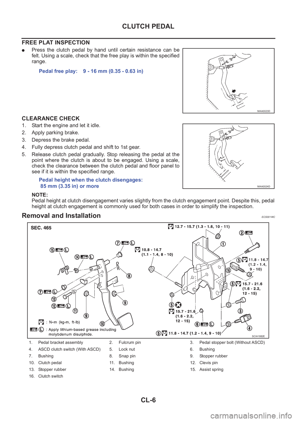
Removal and InstallationECS001WC
Pedal free play: 9 - 16 mm (0.35 - 0.63 in)
MAA0023D
Pedal height when the clutch disengages:
85 mm (3.35 in) or more
MAA0024D
1. Pedal bracket assembly 2. Fulcrum pin 3. Pedal stopper bolt (Without ASCD)
4. ASCD clutch switch (With ASCD) 5. Lock nut 6. Bushing
7. Bushing 8. Snap pin 9. Stopper rubber
10. Clutch pedal 11. Bushing 12. Clevis pin
13. Stopper rubber 14. Bushing 15. Assist spring
16. Clutch switch
SCIA1882E
Page 2023 of 3833
TRANSAXLE ASSEMBLY
MT-47
D
E
F
G
H
I
J
K
L
MA
B
MT
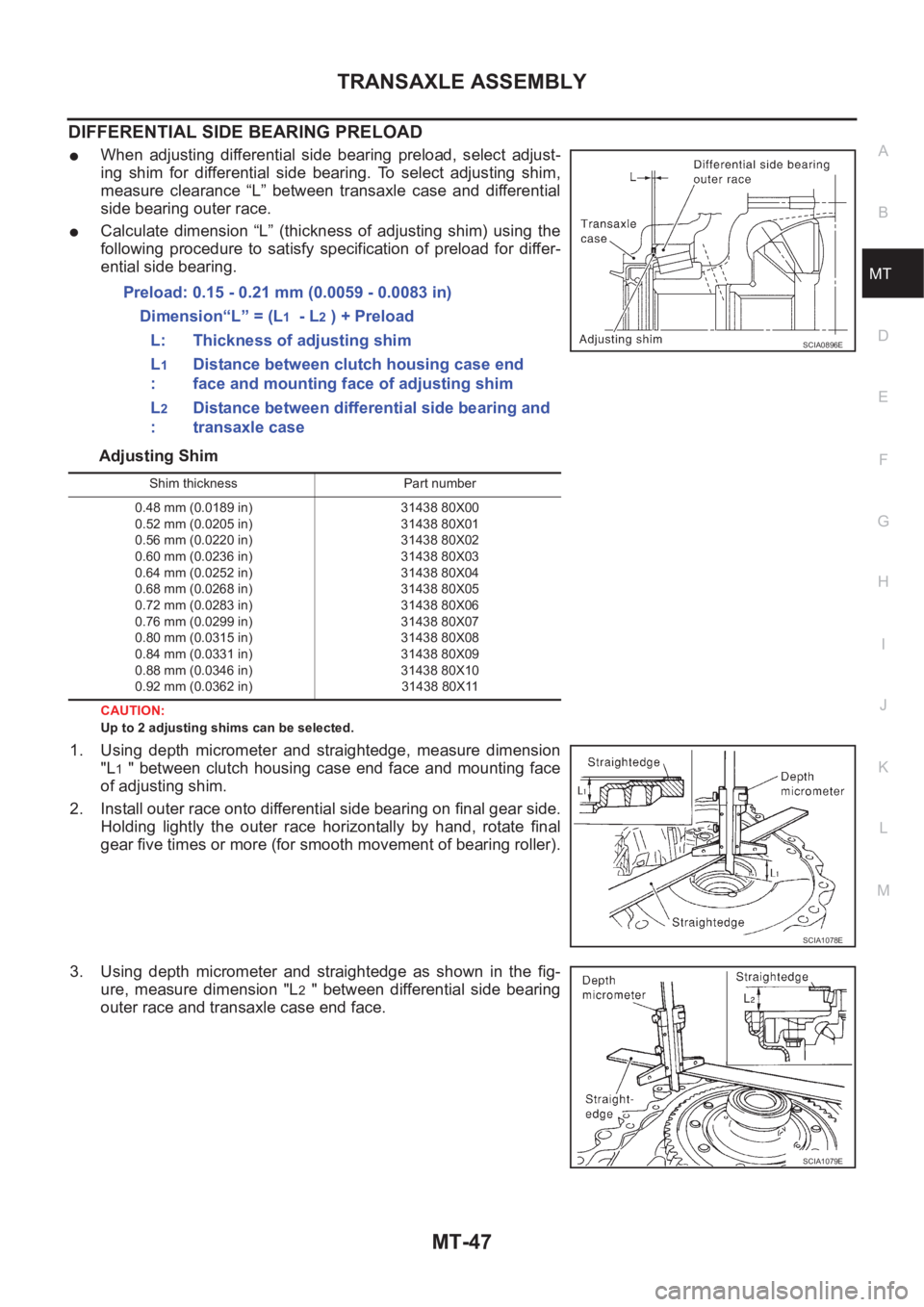
DIFFERENTIAL SIDE BEARING PRELOAD
●When adjusting differential side bearing preload, select adjust-
ing shim for differential side bearing. To select adjusting shim,
measure clearance “L” between transaxle case and differential
side bearing outer race.
●Calculate dimension “L” (thickness of adjusting shim) using the
following procedure to satisfy specification of preload for differ-
ential side bearing.
Adjusting Shim
CAUTION:
Up to 2 adjusting shims can be selected.
1. Using depth micrometer and straightedge, measure dimension
"L
1 " between clutch housing case end face and mounting face
of adjusting shim.
2. Install outer race onto differential side bearing on final gear side.
Holding lightly the outer race horizontally by hand, rotate final
gear five times or more (for smooth movement of bearing roller).
3. Using depth micrometer and straightedge as shown in the fig-
ure, measure dimension "L
2 " between differential side bearing
outer race and transaxle case end face.Preload: 0.15 - 0.21 mm (0.0059 - 0.0083 in)
Dimension“L” = (L
1 - L2 ) + Preload
L: Thickness of adjusting shim
L
1
:Distance between clutch housing case end
face and mounting face of adjusting shim
L
2
:Distance between differential side bearing and
transaxle case
SCIA0896E
Shim thickness Part number
0.48 mm (0.0189 in)
0.52 mm (0.0205 in)
0.56 mm (0.0220 in)
0.60 mm (0.0236 in)
0.64 mm (0.0252 in)
0.68 mm (0.0268 in)
0.72 mm (0.0283 in)
0.76 mm (0.0299 in)
0.80 mm (0.0315 in)
0.84 mm (0.0331 in)
0.88 mm (0.0346 in)
0.92 mm (0.0362 in)31438 80X00
31438 80X01
31438 80X02
31438 80X03
31438 80X04
31438 80X05
31438 80X06
31438 80X07
31438 80X08
31438 80X09
31438 80X10
31438 80X11
SCIA1078E
SCIA1079E
Page 2027 of 3833
TRANSAXLE ASSEMBLY
MT-51
D
E
F
G
H
I
J
K
L
MA
B
MT
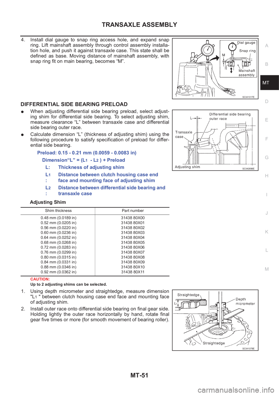
4. Install dial gauge to snap ring access hole, and expand snap
ring. Lift mainshaft assembly through control assembly installa-
tion hole, and push it against transaxle case. This state shall be
defined as base. Moving distance of mainshaft assembly, with
snap ring fit on main bearing, becomes “M”.
DIFFERENTIAL SIDE BEARING PRELOAD
●When adjusting differential side bearing preload, select adjust-
ing shim for differential side bearing. To select adjusting shim,
measure clearance “L” between transaxle case and differential
side bearing outer race.
●Calculate dimension “L” (thickness of adjusting shim) using the
following procedure to satisfy specification of preload for differ-
ential side bearing.
Adjusting Shim
CAUTION:
Up to 2 adjusting shims can be selected.
1. Using depth micrometer and straightedge, measure dimension
"L
1 " between clutch housing case end face and mounting face
of adjusting shim.
2. Install outer race onto differential side bearing on final gear side.
Holding lightly the outer race horizontally by hand, rotate final
gear five times or more (for smooth movement of bearing roller).
SCIA1017E
Preload: 0.15 - 0.21 mm (0.0059 - 0.0083 in)
Dimension“L” = (L
1 - L2 ) + Preload
L: Thickness of adjusting shim
L
1
:Distance between clutch housing case end
face and mounting face of adjusting shim
L
2
:Distance between differential side bearing and
transaxle case
SCIA0896E
Shim thickness Part number
0.48 mm (0.0189 in)
0.52 mm (0.0205 in)
0.56 mm (0.0220 in)
0.60 mm (0.0236 in)
0.64 mm (0.0252 in)
0.68 mm (0.0268 in)
0.72 mm (0.0283 in)
0.76 mm (0.0299 in)
0.80 mm (0.0315 in)
0.84 mm (0.0331 in)
0.88 mm (0.0346 in)
0.92 mm (0.0362 in)31438 80X00
31438 80X01
31438 80X02
31438 80X03
31438 80X04
31438 80X05
31438 80X06
31438 80X07
31438 80X08
31438 80X09
31438 80X10
31438 80X11
SCIA1078E
Page 2080 of 3833
AT-2
DTC P0732 A/T 2ND GEAR FUNCTION ................137
Description ............................................................137
Wiring Diagram — AT — 2ND ..............................140
Diagnostic Procedure ...........................................141
Component Inspection ..........................................142
DTC P0733 A/T 3RD GEAR FUNCTION ................143
Description ............................................................143
Wiring Diagram — AT — 3RD ..............................146
Diagnostic Procedure ...........................................147
Component Inspection ..........................................148
DTC P0734 A/T 4TH GEAR FUNCTION ................149
Description ............................................................149
Wiring Diagram — AT — 4TH ...............................152
Diagnostic Procedure ...........................................153
Component Inspection ..........................................156
DTC P0740 TORQUE CONVERTER CLUTCH
SOLENOID VALVE .................................................158
Description ............................................................158
Wiring Diagram — AT — TCV ..............................160
Diagnostic Procedure ...........................................161
Component Inspection ..........................................162
DTC P0745 LINE PRESSURE SOLENOID VALVE .163
Description ............................................................163
Wiring Diagram — AT — LPSV ............................165
Diagnostic Procedure ...........................................166
Component Inspection ..........................................168
DTC P0750 SHIFT SOLENOID VALVE A ...............170
Description ............................................................170
Wiring Diagram — AT — SSV/A ...........................172
Diagnostic Procedure ...........................................173
Component Inspection ..........................................174
DTC P0755 SHIFT SOLENOID VALVE B ...............175
Description ............................................................175
Wiring Diagram — AT — SSV/B ...........................177
Diagnostic Procedure ...........................................178
Component Inspection ..........................................179
DTC P1705 ACCELERATOR PEDAL POSITION
(APP) SENSOR .......................................................180
Description ............................................................180
Wiring Diagram — AT — TPS ..............................182
Diagnostic Procedure ...........................................183
DTC P1760 OVERRUN CLUTCH SOLENOID
VALVE .....................................................................185
Description ............................................................185
Wiring Diagram — AT — OVRCSV ......................187
Diagnostic Procedure ...........................................188
Component Inspection ..........................................189
DTC U1000 CAN COMMUNICATION LINE ...........
.190
Description ............................................................190
On Board Diagnosis Logic ....................................190
DTC Confirmation Procedure ...............................190
Wiring Diagram — AT — CAN ..............................191
Diagnostic Procedure ...........................................192
DTC BATT/FLUID TEMP SEN (A/T FLUID TEMP
SENSOR CIRCUIT AND TCM POWER SOURCE) .193
Description ............................................................193
Wiring Diagram — AT — BA/FTS .........................195
Diagnostic Procedure ...........................................196
Component Inspection ..........................................198DTC VEHICLE SPEED SENSOR MTR ...................199
Description ............................................................199
Wiring Diagram — AT — VSSMTR .......................201
Diagnostic Procedure ............................................202
DTC CONTROL UNIT (RAM), CONTROL UNIT
(ROM) ......................................................................203
Description ............................................................203
Diagnostic Procedure ............................................203
DTC CONTROL UNIT(EEPROM) ...........................205
Description ............................................................205
Diagnostic Procedure ............................................206
TROUBLE DIAGNOSES FOR SYMPTOMS ...........207
Wiring Diagram — AT — NONDTC ......................207
O/D OFF Indicator Lamp Does Not Come On ......209
Engine Cannot Be Started In “P” and “N” Position .211
In “P” Position, Vehicle Moves Forward Or Back-
ward When Pushed ...............................................212
In “N” Position, Vehicle Moves ..............................213
Large Shock. “N” → “R” Position ..........................214
Vehicle Does Not Creep Backward In “R” Position .215
Vehicle Does Not Creep Forward In “D”, “2” Or “1”
Position .................................................................218
Vehicle Cannot Be Started From D
1 .....................220
A/T Does Not Shift: D
1→ D2 Or Does Not Kickdown:
D
4→ D2 ...............................................................
.223
A/T Does Not Shift: D
2→ D3 ................................225
A/T Does Not Shift: D
3→ D4 ................................227
A/T Does Not Perform Lock-up .............................229
A/T Does Not Hold Lock-up Condition ..................230
Lock-up Is Not Released .......................................232
Engine Speed Does Not Return To Idle (Light Brak-
ing D
4→ D3 ) ........................................................233
Vehicle Does Not Start From D
1 ...........................234
A / T D o e s N o t S h i f t : D
4→ D3 , W h e n O v e r d r i v e C o n -
trol Switch “ON” → “OFF” .....................................236
A/T Does Not Shift: D
3→ 22 , W h e n S e l e c t o r L e v e r
“D” → “2” Position .................................................237
A/T Does Not Shift: 2
2→ 11 , When Selector Lever
“2” → “1” Position ..................................................238
Vehicle Does Not Decelerate By Engine Brake ....240
TCM Self-diagnosis Does Not Activate .................241
EXC.F/EURO-OBD
ON BOARD DIAGNOSTIC SYSTEM DESCRIP-
TION ........................................................................247
CONSULT-II ..........................................................247
Diagnostic Procedure Without CONSULT-II .........253
TROUBLE DIAGNOSIS — INTRODUCTION .........258
Introduction ...........................................................258
Work Flow .............................................................262
TROUBLE DIAGNOSIS — BASIC INSPECTION ...264
A/T Fluid Check ....................................................264
Stall Test ................................................................265
Line Pressure Test ................................................268
Road Test ..............................................................269
TROUBLE DIAGNOSIS — GENERAL DESCRIP-
Page 2081 of 3833
AT-3
D
E
F
G
H
I
J
K
L
MA
B
AT TION ........................................................................ 287
Symptom Chart .................................................... 287
TCM Terminals and Reference Value ................... 306
CAN COMMUNICATION ........................................ 309
System Description .............................................. 309
TROUBLE DIAGNOSES FOR SYMPTOMS .......... 310
Wiring Diagram — AT — NONDTC ...................... 310
O/D OFF Indicator Lamp Does Not Come On ..... 312
Engine Cannot Be Started In “P” and “N” Position . 314
In “P” Position, Vehicle Moves Forward Or Back-
ward When Pushed .............................................. 315
In “N” Position, Vehicle Moves ............................. 315
Large Shock. “N” → “R” Position .......................... 317
Vehicle Does Not Creep Backward In “R” Position . 318
Vehicle Does Not Creep Forward In “D”, “2” Or “1”
Position ................................................................ 321
Vehicle Cannot Be Started From D
1 ..................... 323
A/T Does Not Shift: D
1→ D2 Or Does Not Kick down:
D
4→ D2 ............................................................... 326
A/T Does Not Shift: D
2→ D3 ............................... 328
A/T Does Not Shift: D
3→ D4 ............................... 330
A/T Does Not Perform Lock-up ............................ 332
A/T Does Not Hold Lock-up Condition ................. 333
Lock-up Is Not Released ...................................... 335
Engine Speed Does Not Return To Idle (Light Brak-
ing D
4→ D3 ) ....................................................... 336
Vehicle Does Not Start From D
1 ........................... 338
A/T Does Not Shift: D
4→ D3 , When Overdrive Con-
trol Switch “ON” → “OFF” ..................................... 339
A/T Does Not Shift: D
3→ 22 , W h e n S e l e c t o r L e v e r
“D”→ “2” Position ................................................ 340
A/T Does Not Shift: 2
2→ 11 , W h e n S e l e c t o r L e v e r
“2” → “1” Position ................................................. 341
Vehicle Does Not Decelerate By Engine Brake ... 343
TCM Self-diagnosis Does Not Activate ................ 344
ALL
MAIN POWER SUPPLY AND GROUND CIRCUIT . 350
Wiring Diagram — AT — MAIN ............................ 350
Diagnostic Procedure ........................................... 351
VEHICLE SPEED SENSOR·A/T (REVOLUTION
SENSOR) ................................................................ 353
Description ........................................................... 353
Wiring Diagram — AT — VSSA/T ........................ 355
Diagnostic Procedure ........................................... 356
DTC VEHICLE SPEED SENSOR MTR .................. 358
Description ........................................................... 358
Wiring Diagram — AT — VSSMTR ...................... 360
Diagnostic Procedure ........................................... 361
ACCELE RATOR PEDAL POSITION (APP) SEN-
SOR ........................................................................ 362
Description ........................................................... 362
Wiring Diagram — AT — TPS .............................. 364
Diagnostic Procedure ........................................... 365
SHIFT SOLENOID VALVE A .................................. 367
Description ........................................................... 367
Wiring Diagram — AT — SSV/A .......................... 369Diagnostic Procedure ...........................................370
Component Inspection ..........................................371
SHIFT SOLENOID VALVE B ..................................372
Description ............................................................372
Wiring Diagram — AT — SSV/B ...........................374
Diagnostic Procedure ...........................................375
Component Inspection ..........................................376
OVERRUN CLUTCH SOLENOID VALVE ...............377
Description ............................................................377
Wiring Diagram — AT — OVRCSV ......................378
Diagnostic Procedure ...........................................379
Component Inspection ..........................................380
TORQUE CONVERTER CLUTCH SOLENOID
VALVE .....................................................................381
Description ............................................................381
Wiring Diagram — AT — TCV ..............................383
Diagnostic Procedure ...........................................384
Component Inspection ..........................................385
BATT/FLUID TEMP SEN (A/T FLUID TEMP SEN-
SOR CIRCUIT AND TCM POWER SOURCE) .......386
Description ............................................................386
Wiring Diagram — AT — BA/FTS .........................388
Diagnostic Procedure ...........................................389
Component Inspection ..........................................391
ENGINE SPEED SIGNAL .......................................392
Description ............................................................392
Wiring Diagram — AT — ENGSS .........................393
Diagnostic Procedure ...........................................394
LINE PRESSURE SOLENOID VALVE ..................
.396
Description ............................................................396
Wiring Diagram — AT — LPSV ............................398
Diagnostic Procedure ...........................................399
Component Inspection ..........................................401
CAN COMMUNICATION LINE ...............................403
Description ............................................................403
On Board Diagnosis Logic ....................................403
Self-Diagnosis Code Confirmation Procedure ......403
Wiring Diagram — AT — CAN ..............................404
Diagnostic Procedure ...........................................405
A/T SHIFT LOCK SYSTEM ....................................406
Description ............................................................406
Shift Lock System Electrical Parts Location .........406
Wiring Diagram — SHIFT — ................................407
Diagnostic Procedure ...........................................408
KEY INTERLOCK CABLE ......................................412
Components .........................................................412
Removal ...............................................................412
Installation ............................................................413
ON-VEHICLE SERVICE ..........................................414
Control Valve Assembly and Accumulators ..........414
Control Cable Adjustment .....................................416
Park/Neutral Position (PNP) Switch Adjustment ..416
Differential Side Oil Seal Replacement ................417
Revolution Sensor Replacement ..........................417
REMOVAL AND INSTALLATION ...........................418
Removal ...............................................................418
Installation ............................................................419
OVERHAUL ............................................................421
Components .........................................................421
Page 2083 of 3833
PRECAUTIONS
AT-5
D
E
F
G
H
I
J
K
L
MA
B
AT
PRECAUTIONSPFP:00001
Precautions for Supplemental Restraint System (SRS) “AIR BAG” and “SEAT
BELT PRE-TENSIONER”
ECS004Q0
The Supplemental Restraint System such as “AIR BAG” and “SEAT BELT PRE-TENSIONER”, used along
with a front seat belt, helps to reduce the risk or severity of injury to the driver and front passenger for certain
types of collision. Information necessary to service the system safely is included in the SRS and SB section of
this Service Manual.
WARNING:
●To avoid rendering the SRS inoperative, which could increase the risk of personal injury or death
in the event of a collision which would result in air bag inflation, all maintenance must be per-
formed by an authorized NISSAN/INFINITI dealer.
●Improper maintenance, including incorrect removal and installation of the SRS, can lead to per-
sonal injury caused by unintentional activation of the system. For removal of Spiral Cable and Air
Bag Module, see the SRS section.
●Do not use electrical test equipment on any circuit related to the SRS unless instructed to in this
Service Manual. SRS wiring harnesses can be identified by yellow and/or orange harness connec-
tors.
Precautions for On Board Diagnostic (EURO-OBD) System of A/T and Engine —
Euro-OBD —
ECS004Q1
The ECM has an on board diagnostic system. It will light up the malfunction indicator lamp (MIL) to warn the
driver of a malfunction causing emission deterioration.
CAUTION:
●Be sure to turn the ignition switch “OFF” and disconnect the negative battery terminal before any
repair or inspection work. The open/short circuit of related switches, sensors, solenoid valves,
etc. will cause the MIL to light up.
●Be sure to connect and lock the connectors securely after work. A loose (unlocked) connector will
cause the MIL to light up due to an open circuit. (Be sure the connector is free from water, grease,
dirt, bent terminals, etc.)
●Be sure to route and secure the harnesses properly after work. Interference of the harness with a
bracket, etc. may cause the MIL to light up due to a short circuit.
●Be sure to connect rubber tubes properly after work. A misconnected or disconnected rubber tube
may cause the MIL to light up due to a malfunction of the EGR system or fuel injection system, etc.
●Be sure to erase the unnecessary malfunction information (repairs completed) from the TCM and
ECM before returning the vehicle to the customer.
Precautions for Trouble DiagnosisECS004VN
CAN SYSTEM
●Do not apply voltage of 7.0V or higher to the measurement terminals.
●Use the tester with its open terminal voltage being 7.0V or less.
Precautions for Harness RepairECS004VO
CAN SYSTEM
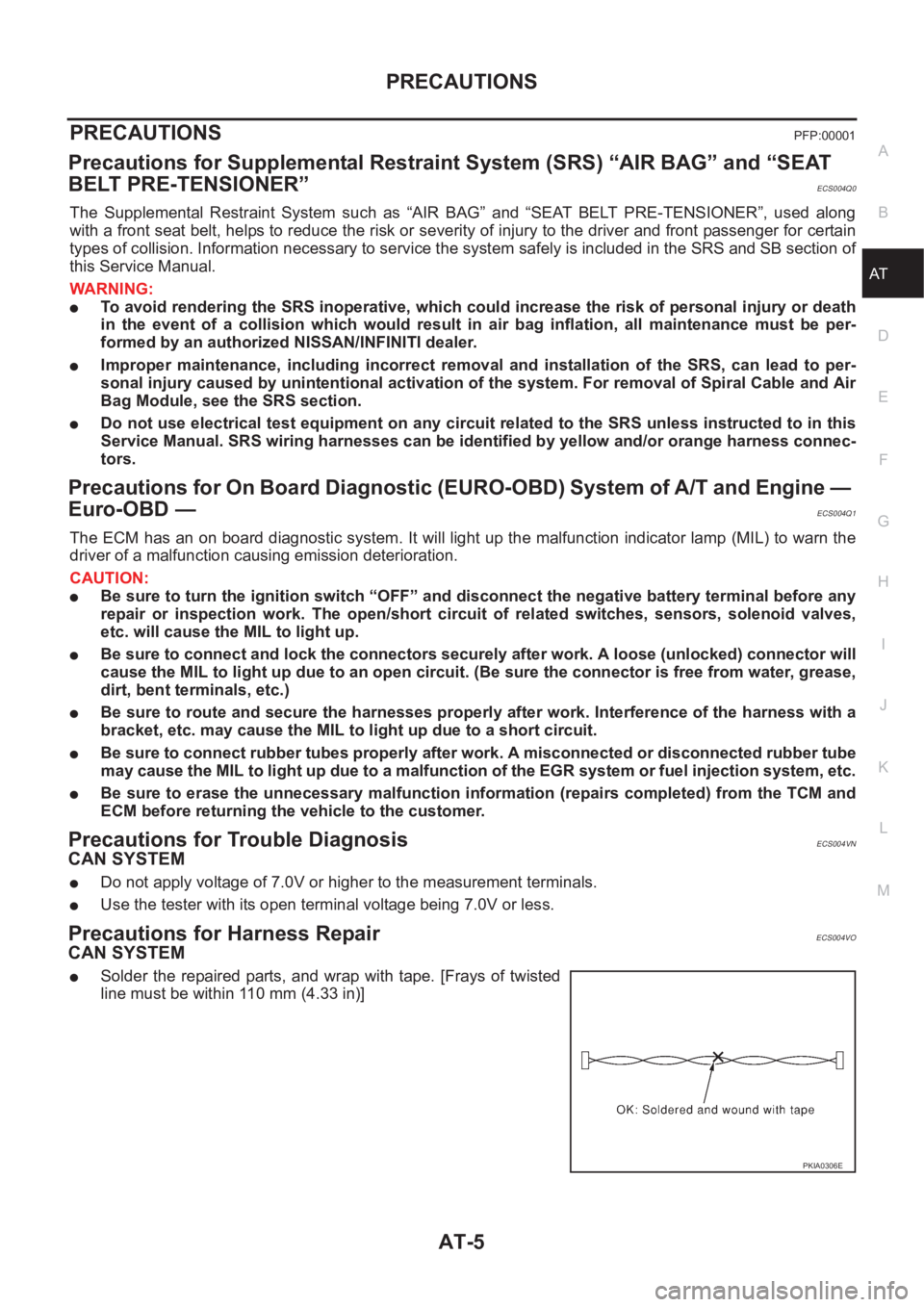
●Solder the repaired parts, and wrap with tape. [Frays of twisted
line must be within 110 mm (4.33 in)]
PKIA0306E
Page 2119 of 3833
![NISSAN X-TRAIL 2001 Service Repair Manual ON BOARD DIAGNOSTIC SYSTEM DESCRIPTION
AT-41
[EURO-OBD]
D
E
F
G
H
I
J
K
L
MA
B
AT
Malfunction Indicator lamp (MIL)ECS004QL
1. The malfunction indicator lamp will light up when the ignition
sw NISSAN X-TRAIL 2001 Service Repair Manual ON BOARD DIAGNOSTIC SYSTEM DESCRIPTION
AT-41
[EURO-OBD]
D
E
F
G
H
I
J
K
L
MA
B
AT
Malfunction Indicator lamp (MIL)ECS004QL
1. The malfunction indicator lamp will light up when the ignition
sw](/manual-img/5/57405/w960_57405-2118.png)
ON BOARD DIAGNOSTIC SYSTEM DESCRIPTION
AT-41
[EURO-OBD]
D
E
F
G
H
I
J
K
L
MA
B
AT
Malfunction Indicator lamp (MIL)ECS004QL
1. The malfunction indicator lamp will light up when the ignition
switch is turned ON without the engine running. This is for
checking the lamp.
●If the malfunction indicator does not light up, refer to DI-43,
"Schematic" .
(Or see MIL & CONSULT-II in EC section. Refer to EC-58,
"Malfunction Indicator (MI)" (QR25DE) or EC-790, "Malfunc-
tion Indicator (MI)" (QR20DE), EC-94, "CONSULT-II Func-
tion" (QR25DE) or EC-826, "CONSULT-II Function"
(QR20DE).
2. When the engine is started, the malfunction indicator should go
off.
If the lamp remains on, the on board diagnostic system has detected an emission-related (EURO-OBD)
malfunction. For detail, refer to EC-44, "
ON BOARD DIAGNOSTIC (OBD) SYSTEM" (QR25DE) or EC-
777, "ON BOARD DIAGNOSTIC (OBD) SYSTEM" (QR20DE).
CONSULT-IIECS004QM
After performing “SELF-DIAGNOSTIC PROCEDURE (WITH CONSULT-II)” AT- 4 1 , place check marks for
results on the “DIAGNOSTIC WORKSHEET”, AT- 5 7
. Reference pages are provided following the items.
NOTICE:
1. The CONSULT-II electrically displays shift timing and lock-up timing (that is, operation timing of each sole-
noid).
Check for time difference between actual shift timing and the CONSULT-II display. If the difference is
noticeable, mechanical parts (except solenoids, sensors, etc.) may be malfunctioning. Check mechanical
parts using applicable diagnostic procedures.
2. Shift schedule (which implies gear position) displayed on CONSULT-II and that indicated in Service Man-
ual may differ slightly. This occurs because of the following reasons:
–Actual shift schedule has more or less tolerance or allowance,
–Shift schedule indicated in Service Manual refers to the point where shifts start, and
–Gear position displayed on CONSULT-II indicates the point where shifts are completed.
3. Shift solenoid valve “A” or “B” is displayed on CONSULT-II at the start of shifting. Gear position is dis-
played upon completion of shifting (which is computed by TCM).
4. Additional CONSULT-II information can be found in the Operation Manual supplied with the CONSULT-II
unit.
SELF-DIAGNOSTIC PROCEDURE (WITH CONSULT-II)
1. Turn on CONSULT-II and touch “ENGINE” for EURO-OBD
detected items or touch “A/T” for TCM self-diagnosis.
If A/T is not displayed, check TCM power supply and ground cir-
cuit. Refer to AT- 1 0 6 , "
TCM Terminals and Reference Value" . If
result is NG, refer to PG-2, "
POWER SUPPLY ROUTING" .
SAT652J
SAT014K
Page 2137 of 3833
![NISSAN X-TRAIL 2001 Service Repair Manual TROUBLE DIAGNOSIS — INTRODUCTION
AT-59
[EURO-OBD]
D
E
F
G
H
I
J
K
L
MA
B
AT
4. 4-3. Cruise testAT- 7 4 , "3.
CRUISE
TEST"
AT- 7 8 ,
"Cruise Test
— Part 1"
Part-1
❏ Vehicle NISSAN X-TRAIL 2001 Service Repair Manual TROUBLE DIAGNOSIS — INTRODUCTION
AT-59
[EURO-OBD]
D
E
F
G
H
I
J
K
L
MA
B
AT
4. 4-3. Cruise testAT- 7 4 , "3.
CRUISE
TEST"
AT- 7 8 ,
"Cruise Test
— Part 1"
Part-1
❏ Vehicle](/manual-img/5/57405/w960_57405-2136.png)
TROUBLE DIAGNOSIS — INTRODUCTION
AT-59
[EURO-OBD]
D
E
F
G
H
I
J
K
L
MA
B
AT
4. 4-3. Cruise testAT- 7 4 , "3.
CRUISE
TEST"
AT- 7 8 ,
"Cruise Test
— Part 1"
Part-1
❏ Vehicle Cannot Be Started From D
1 , AT- 2 2 0 , "Vehicle Cannot Be Started From D1" .
❏ A/T Does Not Shift: D
1→ D2 Or Does Not Kickdown: D4→ D2 , AT-223, "A/T Does Not Shift: D1→
D2 Or Does Not Kickdown: D4→ D2" .
❏ A/T Does Not Shift: D
2→ D3 , AT- 2 2 5 , "A/T Does Not Shift: D2→ D3" .
❏ A/T Does Not Shift: D
3→ D4 , AT- 2 2 7 , "A/T Does Not Shift: D3→ D4" .
❏ A/T Does Not Perform Lock-up, AT-229, "
A/T Does Not Perform Lock-up" .
❏ A/T Does Not Hold Lock-up Condition, AT-230, "
A/T Does Not Hold Lock-up Condition" .
❏ Lock-up Is Not Released, AT-232, "
Lock-up Is Not Released" .
❏ Engine Speed Does Not Return To Idle (Light Braking D
4→ D3 ), AT-233, "Engine Speed Does Not
Return To Idle (Light Braking D4→ D3 )" .
Part-2AT- 8 1 ,
"Cruise Test
— Part 2"❏ Vehicle Does Not Start From D1 , AT- 2 3 4 , "Vehicle Does Not Start From D1" .
❏ A/T Does Not Shift: D
1→ D2 Or Does Not Kickdown: D4→ D2 , AT-223, "A/T Does Not Shift: D1→
D2 Or Does Not Kickdown: D4→ D2" .
❏ A/T Does Not Shift: D
2→ D3 , AT- 2 2 5 , "A/T Does Not Shift: D2→ D3" .
❏ A/T Does Not Shift: D
3→ D4 , AT- 2 2 7 , "A/T Does Not Shift: D3→ D4" .
Part-3AT- 8 3 ,
"Cruise Test
— Part 3"❏ A/T Does Not Shift: D4→ D3 When Overdrive Control Switch “ON” → “OFF”, AT-236, "A/T Does Not
Shift: D4→ D3 , When Overdrive Control Switch “ON”→“OFF”" .
❏ Engine Speed Does Not Return To Idle (Engine Brake In D
3 ), AT-233, "Engine Speed Does Not Return
To Idle (Light Braking D4→ D3 )" .
❏ A/T Does Not Shift: D
3→ 22 , When Selector Lever “D” → “2” Position, AT- 2 3 7 , "A/T Does Not Shift:
D3→ 22 , When Selector Lever “D”→“2” Position" .
❏ Engine Speed Does Not Return To Idle (Engine Brake In 2
2 ), AT- 2 3 3 , "Engine Speed Does Not Return
To Idle (Light Braking D4→ D3 )" .
❏ A/T Does Not Shift: 2
2→ 11 , When Selector Lever “2” → “1” Position, AT-238, "A/T Does Not Shift: 22
→ 11 , When Selector Lever “2”→“1” Position" .
❏ Vehicle Does Not Decelerate By Engine Brake, AT- 2 4 0 , "
Vehicle Does Not Decelerate By Engine
Brake" .
❏ TCM Self-diagnosis Does Not Activate (PNP & Overdrive control switches, and throttle position sensor
circuit checks), AT-241, "
TCM Self-diagnosis Does Not Activate" .
❏ SELF-DIAGNOSTIC PROCEDURE/DIAGNOSTIC TROUBLE CODE (DTC) CONFIRMATION PRO-
CEDURE — Mark detected items.
❏ PNP switch, AT- 11 0 , "
DTC P0705 PARK/NEUTRAL POSITION (PNP) SWITCH" .
❏ A/T fluid temperature sensor, AT- 11 6 , "
DTC P0710 A/T FLUID TEMPERATURE SENSOR CIR-
CUIT" .
❏ Vehicle speed sensor·A/T (Revolution sensor), AT- 1 2 2 , "
DTC P0720 VEHICLE SPEED SEN-
SOR·A/T (REVOLUTION SENSOR)" .
❏ Engine speed signal, AT- 1 2 7 , "
DTC P0725 ENGINE SPEED SIGNAL" .
❏ Torque converter clutch solenoid valve, AT-158, "
DTC P0740 TORQUE CONVERTER CLUTCH
SOLENOID VALVE" .
❏ Line pressure solenoid valve, AT-163, "
DTC P0745 LINE PRESSURE SOLENOID VALVE" .
❏ Shift solenoid valve A, AT- 1 7 0 , "
DTC P0750 SHIFT SOLENOID VALVE A" .
❏ Shift solenoid valve B, AT- 1 7 5 , "
DTC P0755 SHIFT SOLENOID VALVE B" .
❏ Accelerator pedal position (App) sensor, AT-180, "
DTC P1705 ACCELERATOR PEDAL POSITION
(APP) SENSOR" .
❏ Overrun clutch solenoid valve, AT- 1 8 5 , "
DTC P1760 OVERRUN CLUTCH SOLENOID VALVE" .
❏ PNP & overdrive control switches, and throttle position sensor, AT-241, "
TCM Self-diagnosis Does
Not Activate" .
❏ A/T fluid temperature sensor and TCM power source, AT-193, "
DTC BATT/FLUID TEMP SEN (A/T
FLUID TEMP SENSOR CIRCUIT AND TCM POWER SOURCE)" .
❏ Vehicle speed sensor·MTR, AT-199, "
DTC VEHICLE SPEED SENSOR MTR" .
❏ CAN communication line, AT- 1 9 0 , "
DTC U1000 CAN COMMUNICATION LINE" .
❏ Control unit (RAM), control unit (ROM), AT-203, "
DTC CONTROL UNIT (RAM), CONTROL UNIT
(ROM)" .
❏ Control unit (EEP ROM), AT-205, "
DTC CONTROL UNIT(EEPROM)" .
❏ Battery
❏ Others