2001 NISSAN ALMERA TINO ECU
[x] Cancel search: ECUPage 121 of 3051
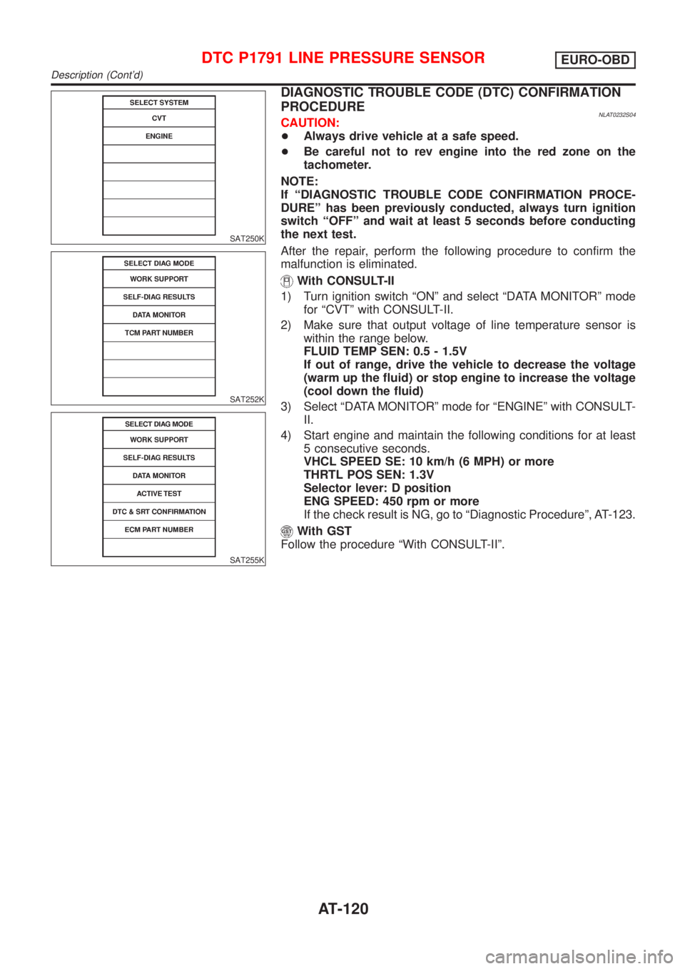
SAT250K
SAT252K
SAT255K
DIAGNOSTIC TROUBLE CODE (DTC) CONFIRMATION
PROCEDURE
NLAT0232S04CAUTION:
+Always drive vehicle at a safe speed.
+Be careful not to rev engine into the red zone on the
tachometer.
NOTE:
If ªDIAGNOSTIC TROUBLE CODE CONFIRMATION PROCE-
DUREº has been previously conducted, always turn ignition
switch ªOFFº and wait at least 5 seconds before conducting
the next test.
After the repair, perform the following procedure to confirm the
malfunction is eliminated.
With CONSULT-II
1) Turn ignition switch ªONº and select ªDATA MONITORº mode
for ªCVTº with CONSULT-II.
2) Make sure that output voltage of line temperature sensor is
within the range below.
FLUID TEMP SEN: 0.5 - 1.5V
If out of range, drive the vehicle to decrease the voltage
(warm up the fluid) or stop engine to increase the voltage
(cool down the fluid)
3) Select ªDATA MONITORº mode for ªENGINEº with CONSULT-
II.
4) Start engine and maintain the following conditions for at least
5 consecutive seconds.
VHCL SPEED SE: 10 km/h (6 MPH) or more
THRTL POS SEN: 1.3V
Selector lever: D position
ENG SPEED: 450 rpm or more
If the check result is NG, go to ªDiagnostic Procedureº, AT-123.
With GST
Follow the procedure ªWith CONSULT-IIº.
DTC P1791 LINE PRESSURE SENSOREURO-OBD
Description (Cont'd)
AT-120
Page 203 of 3051
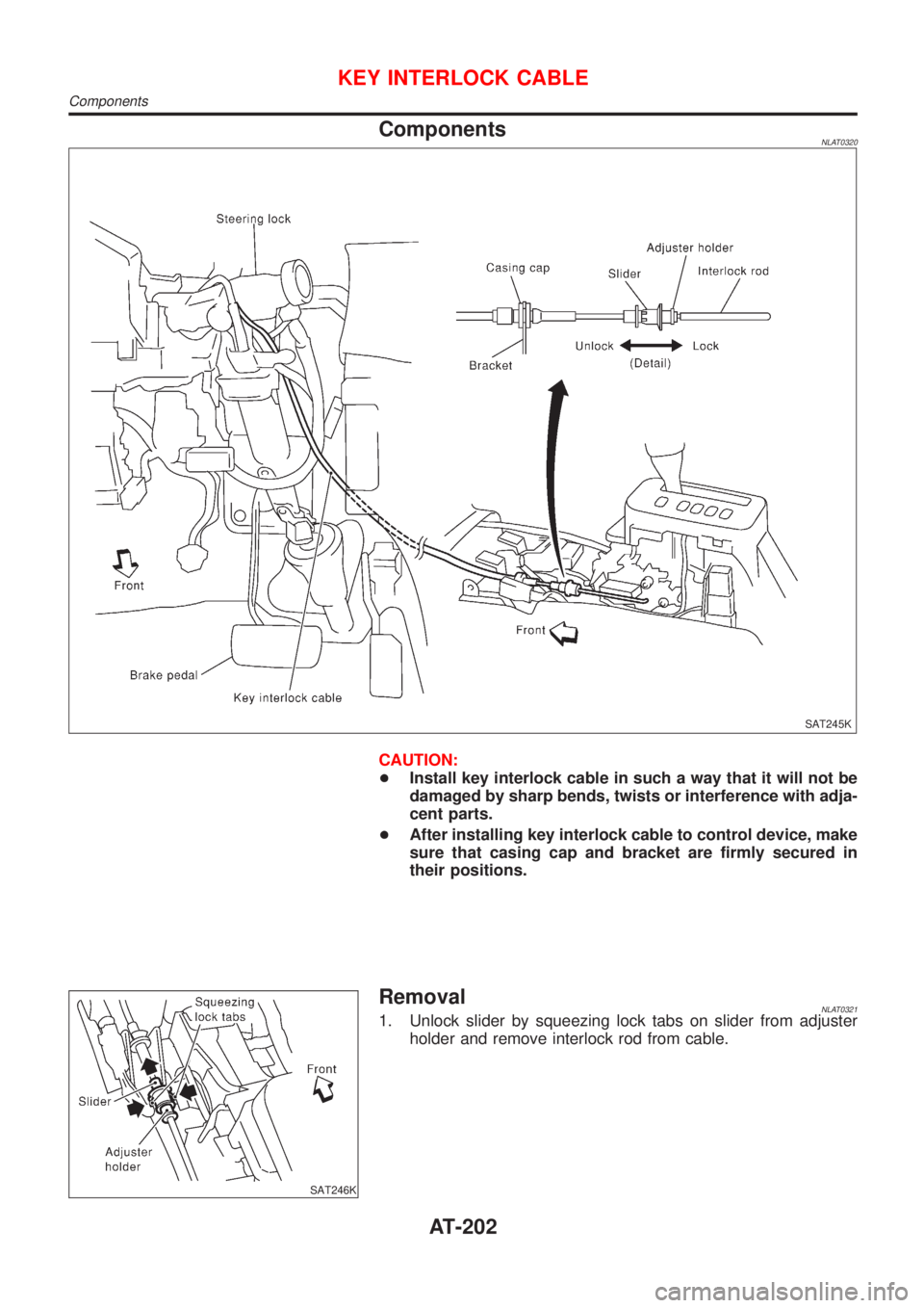
ComponentsNLAT0320
SAT245K
CAUTION:
+Install key interlock cable in such a way that it will not be
damaged by sharp bends, twists or interference with adja-
cent parts.
+After installing key interlock cable to control device, make
sure that casing cap and bracket are firmly secured in
their positions.
SAT246K
RemovalNLAT03211. Unlock slider by squeezing lock tabs on slider from adjuster
holder and remove interlock rod from cable.
KEY INTERLOCK CABLE
Components
AT-202
Page 207 of 3051
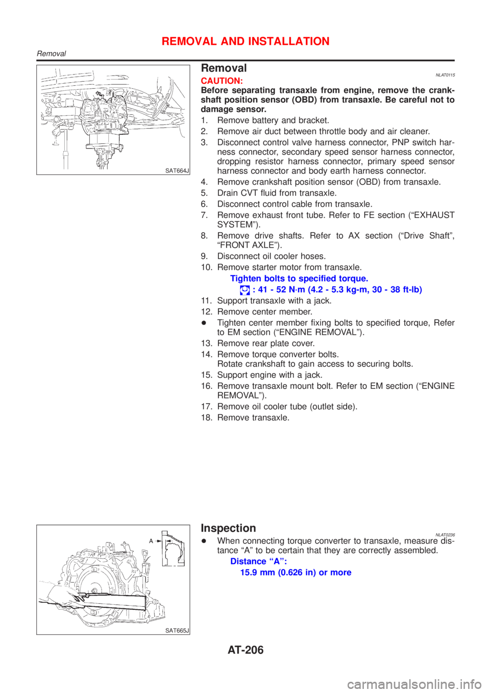
SAT664J
RemovalNLAT0115CAUTION:
Before separating transaxle from engine, remove the crank-
shaft position sensor (OBD) from transaxle. Be careful not to
damage sensor.
1. Remove battery and bracket.
2. Remove air duct between throttle body and air cleaner.
3. Disconnect control valve harness connector, PNP switch har-
ness connector, secondary speed sensor harness connector,
dropping resistor harness connector, primary speed sensor
harness connector and body earth harness connector.
4. Remove crankshaft position sensor (OBD) from transaxle.
5. Drain CVT fluid from transaxle.
6. Disconnect control cable from transaxle.
7. Remove exhaust front tube. Refer to FE section (ªEXHAUST
SYSTEMº).
8. Remove drive shafts. Refer to AX section (ªDrive Shaftº,
ªFRONT AXLEº).
9. Disconnect oil cooler hoses.
10. Remove starter motor from transaxle.
Tighten bolts to specified torque.
: 41 - 52 N´m (4.2 - 5.3 kg-m, 30 - 38 ft-lb)
11. Support transaxle with a jack.
12. Remove center member.
+Tighten center member fixing bolts to specified torque, Refer
to EM section (ªENGINE REMOVALº).
13. Remove rear plate cover.
14. Remove torque converter bolts.
Rotate crankshaft to gain access to securing bolts.
15. Support engine with a jack.
16. Remove transaxle mount bolt. Refer to EM section (ªENGINE
REMOVALº).
17. Remove oil cooler tube (outlet side).
18. Remove transaxle.
SAT665J
InspectionNLAT0236+When connecting torque converter to transaxle, measure dis-
tance ªAº to be certain that they are correctly assembled.
Distance ªAº:
15.9 mm (0.626 in) or more
REMOVAL AND INSTALLATION
Removal
AT-206
Page 226 of 3051
+Use grease according to AX-19, SDS.
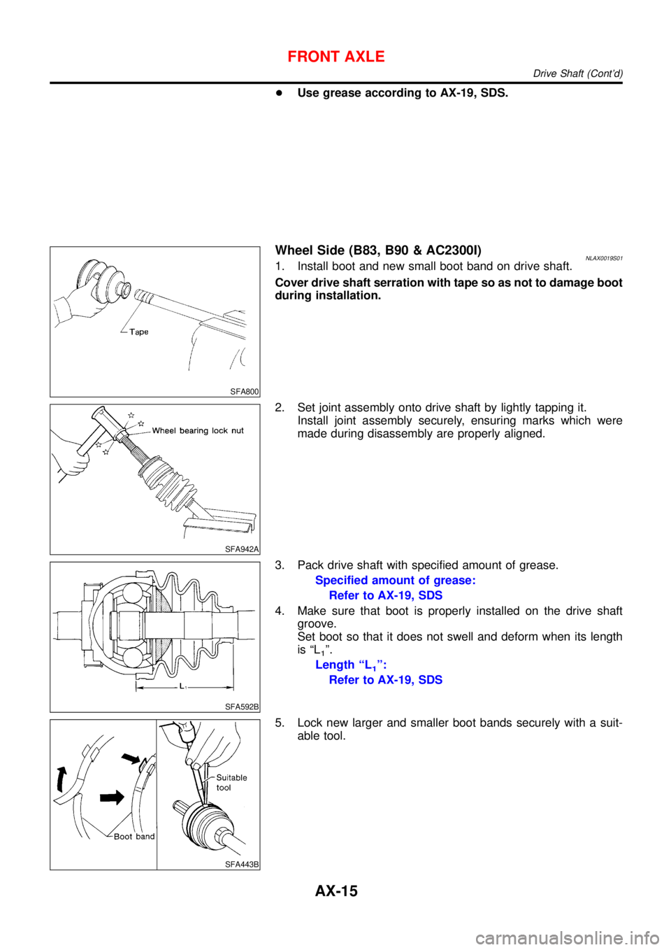
SFA800
Wheel Side (B83, B90 & AC2300I)NLAX0019S011. Install boot and new small boot band on drive shaft.
Cover drive shaft serration with tape so as not to damage boot
during installation.
SFA942A
2. Set joint assembly onto drive shaft by lightly tapping it.
Install joint assembly securely, ensuring marks which were
made during disassembly are properly aligned.
SFA592B
3. Pack drive shaft with specified amount of grease.
Specified amount of grease:
Refer to AX-19, SDS
4. Make sure that boot is properly installed on the drive shaft
groove.
Set boot so that it does not swell and deform when its length
is“L
1”.
Length“L
1”:
Refer to AX-19, SDS
SFA443B
5. Lock new larger and smaller boot bands securely with a suit-
able tool.
FRONT AXLE
Drive Shaft (Cont’d)
AX-15
Page 227 of 3051
SFA313B
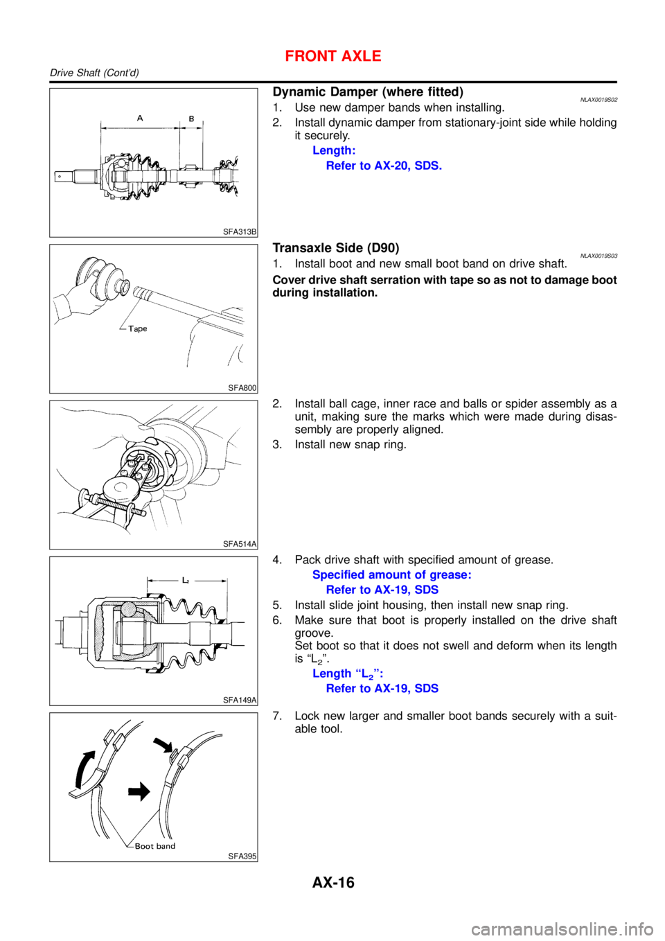
Dynamic Damper (where fitted)NLAX0019S021. Use new damper bands when installing.
2. Install dynamic damper from stationary-joint side while holding
it securely.
Length:
Refer to AX-20, SDS.
SFA800
Transaxle Side (D90)NLAX0019S031. Install boot and new small boot band on drive shaft.
Cover drive shaft serration with tape so as not to damage boot
during installation.
SFA514A
2. Install ball cage, inner race and balls or spider assembly as a
unit, making sure the marks which were made during disas-
sembly are properly aligned.
3. Install new snap ring.
SFA149A
4. Pack drive shaft with specified amount of grease.
Specified amount of grease:
Refer to AX-19, SDS
5. Install slide joint housing, then install new snap ring.
6. Make sure that boot is properly installed on the drive shaft
groove.
Set boot so that it does not swell and deform when its length
is“L
2”.
Length“L
2”:
Refer to AX-19, SDS
SFA395
7. Lock new larger and smaller boot bands securely with a suit-
able tool.
FRONT AXLE
Drive Shaft (Cont’d)
AX-16
Page 228 of 3051
SFA800
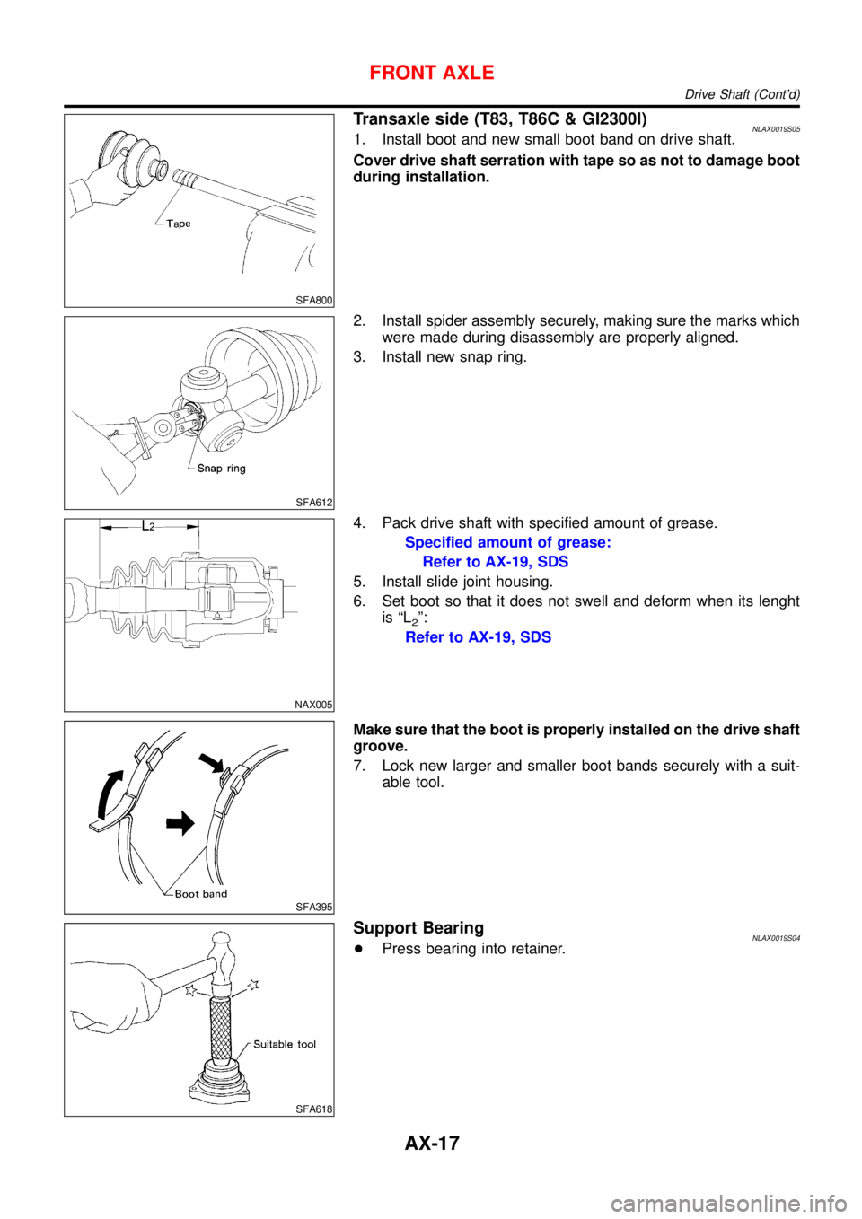
Transaxle side (T83, T86C & GI2300I)NLAX0019S051. Install boot and new small boot band on drive shaft.
Cover drive shaft serration with tape so as not to damage boot
during installation.
SFA612
2. Install spider assembly securely, making sure the marks which
were made during disassembly are properly aligned.
3. Install new snap ring.
NAX005
4. Pack drive shaft with specified amount of grease.
Specified amount of grease:
Refer to AX-19, SDS
5. Install slide joint housing.
6. Set boot so that it does not swell and deform when its lenght
is“L
2”:
Refer to AX-19, SDS
SFA395
Make sure that the boot is properly installed on the drive shaft
groove.
7. Lock new larger and smaller boot bands securely with a suit-
able tool.
SFA618
Support BearingNLAX0019S04+Press bearing into retainer.
FRONT AXLE
Drive Shaft (Cont’d)
AX-17
Page 239 of 3051
CALIPER.................................................................38
ROTOR...................................................................39
Installation ..................................................................39
PARKING BRAKE CONTROL......................................40
Components...............................................................40
Removal and Installation ...........................................40
Inspection...................................................................40
Adjustment .................................................................41
ABS
DESCRIPTION...............................................................42
Purpose......................................................................42
ABS (Anti-Lock Brake System) Operation ................42
ABS Hydraulic Circuit ................................................42
System Components .................................................43
System Description ....................................................43
SENSOR.................................................................43
CONTROL UNIT......................................................43
ABS ACTUATOR AND ELECTRIC UNIT....................43
Component Parts and Harness Connector
Location .....................................................................45
Schematic ..................................................................46
MODELS WITH SELF-DIAGNOSIS FUNCTION
(DATA LINK CONNECTOR TERMINAL NO. 9)
...........46
MODELS WITHOUT SELF-DIAGNOSIS
FUNCTION (DATA LINK CONNECTOR TERMINAL
NO. 9)
.....................................................................47
Wiring Diagram - ABS - .............................................48
MODELS WITH SELF-DIAGNOSIS FUNCTION
(DATA LINK CONNECTOR TERMINAL NO. 9)
...........48
MODELS WITHOUT SELF-DIAGNOSIS
FUNCTION (DATA LINK CONNECTOR TERMINAL
NO. 9)
.....................................................................52
ON BOARD DIAGNOSTIC SYSTEM
DESCRIPTION...............................................................56
Self-diagnosis (Only models with data link
connector terminal No. 9) ..........................................56
FUNCTION..............................................................56
SELF-DIAGNOSIS PROCEDURE..............................56
HOW TO READ SELF-DIAGNOSTIC RESULTS
(MALFUNCTION CODES)
........................................57
HOW TO ERASE SELF-DIAGNOSTIC RESULTS
(MALFUNCTION CODES)
........................................57
CONSULT-II ...............................................................58
CONSULT-II APPLICATION TO ABS..........................58
ECU (ABS CONTROL UNIT) PART NUMBER
MODE
.....................................................................58
CONSULT-II Inspection Procedure............................58
SELF-DIAGNOSIS PROCEDURE..............................58
SELF-DIAGNOSTIC RESULTS MODE.......................60
DATA MONITOR PROCEDURE................................61
ACTIVE TEST PROCEDURE....................................62
DATA MONITOR MODE...........................................63
ACTIVE TEST MODE...............................................63
TROUBLE DIAGNOSIS - INTRODUCTION..................64
How to Perform Trouble Diagnoses for Quick
and Accurate Repair ..................................................64
INTRODUCTION......................................................64
TROUBLE DIAGNOSIS - BASIC INSPECTION...........65
Preliminary Check......................................................65
Ground Circuit Check ................................................68
ABS ACTUATOR AND ELECTRIC UNIT GROUND.....68
TROUBLE DIAGNOSIS - GENERAL
DESCRIPTION...............................................................69
Malfunction Code/Symptom Chart.............................69
MODELS WITH SELF-DIAGNOSIS FUNCTION
(DATA LINK CONNECTOR TERMINAL NO. 9)
...........69
TROUBLE DIAGNOSES FOR SELF-DIAGNOSTIC
ITEMS.............................................................................71
Wheel Sensor or Rotor ..............................................71
DIAGNOSTIC PROCEDURE.....................................71
ABS Actuator Solenoid Valve or Solenoid Valve
Relay ..........................................................................74
DIAGNOSTIC PROCEDURE.....................................74
Motor Relay or Motor.................................................77
DIAGNOSTIC PROCEDURE.....................................77
Low Voltage ...............................................................79
DIAGNOSTIC PROCEDURE.....................................79
Control Unit ................................................................81
DIAGNOSTIC PROCEDURE.....................................81
TROUBLE DIAGNOSES FOR SYMPTOMS.................82
1. ABS Works Frequently ..........................................82
2. Unexpected Pedal Action ......................................82
3. Long Stopping Distance ........................................83
4. ABS Does Not Work ..............................................84
5. Pedal Vibration and Noise.....................................85
6. ABS Warning Lamp Does Not Come On
When Ignition Switch Is Turned On...........................86
7. ABS Warning Lamp Stays On When Ignition
Switch Is Turned On ..................................................88
REMOVAL AND INSTALLATION.................................90
Wheel Sensors ..........................................................90
ABS Actuator and Electric Unit..................................91
REMOVAL...............................................................91
INSTALLATION........................................................91
Sensor Rotor..............................................................92
REMOVAL...............................................................92
INSTALLATION........................................................92
SERVICE DATA AND SPECIFICATIONS (SDS).........93
General Specifications ...............................................93
Disc Brake .................................................................93
Brake Pedal ...............................................................93
Parking Brake ............................................................93
CONTENTS(Cont’d)
BR-2
Page 251 of 3051

NBR353
3. Remove the circlip with suitable pliers while piston is pushed
into cylinder.
SBR232E
4. Remove piston stopper pin while piston is pushed into cylinder.
5. Remove piston assemblies.
If it is difficult to remove secondary piston assembly,
gradually apply compressed air through fluid outlet.
InspectionNLBR0119Check for the following items.
Replace any part if damaged.
Master cylinder:
+Pin holes or scratches on inner wall.
Piston:
+Deformation or scratches on piston cups.
SBR233E
AssemblyNLBR01201. Insert secondary piston assembly. Then insert primary piston
assembly.
+Pay attention to alignment of secondary piston slit with
valve stopper mounting hole of cylinder body.
SBR232E
2. Install piston stopper pin while piston is pushed into cylinder.
Then secure the primary and secondary piston assemblies
with new circlip.
3. Insert washer and push reservoir seals and adapter into cylin-
der body.
4. Install elastic pin.
MASTER CYLINDER
Disassembly (Cont’d)
BR-14