Page 252 of 3051

InstallationNLBR0121CAUTION:
+Refill with new brake fluid“DOT 4”.
+Never reuse drained brake fluid.
1. Place master cylinder onto brake booster and secure mount-
ing nuts lightly.
2. Torque mounting nuts.
:13-15N·m (1.3 - 1.5 kg-m,9-11ft-lb)
NBR363
NBR364
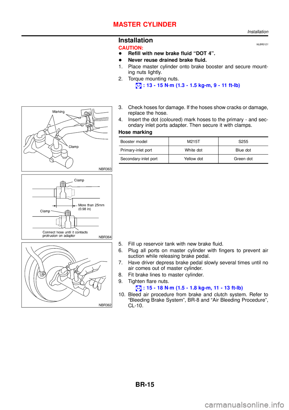
3. Check hoses for damage. If the hoses show cracks or damage,
replace the hose.
4. Insert the dot (coloured) mark hoses to the primary - and sec-
ondary inlet ports adapter. Then secure it with clamps.
Hose marking
Booster model M215T S255
Primary-inlet port White dot Blue dot
Secondary-inlet port Yellow dot Green dot
NBR362
5. Fill up reservoir tank with new brake fluid.
6. Plug all ports on master cylinder with fingers to prevent air
suction while releasing brake pedal.
7. Have driver depress brake pedal slowly several times until no
air comes out of master cylinder.
8. Fit brake lines to master cylinder.
9. Tighten flare nuts.
:15-18N·m (1.5 - 1.8 kg-m, 11 - 13 ft-lb)
10. Bleed air procedure from brake and clutch system. Refer to
“Bleeding Brake System”, BR-8 and“Air Bleeding Procedure”,
CL-10.
MASTER CYLINDER
Installation
BR-15
Page 254 of 3051
InstallationNLBR0026CAUTION:
+Be careful not to deform or bend brake pipes, during
booster installation.
+Replace clevis pin if damaged.
+Refill with new brake fluid“DOT 4”.
+Never reuse drained brake fluid.
+Take care not to damage brake booster mounting bolt
thread during installation. Due to the acute angle of
installation, the threads can be damaged with the dash
panel.
SBR237EA
1. Before fitting booster, temporarily adjust clevis to dimension
shown.
2. Fit booster, then secure mounting nuts (brake pedal bracket to
master cylinder) lightly.
3. Connect brake pedal and booster input rod with clevis pin.
4. Secure mounting nuts.
Specification:
13-16N·m (1.3 - 1.6 kg-m,9-12ft-lb)
5. Install master cylinder. Refer to“Installation”in“MASTER
CYLINDER”, BR-15.
6. Bleed air. Refer to“Bleeding Brake System”, BR-8 and“Air
Bleeding Procedure”, CL-10.
BRAKE BOOSTER
Installation
BR-17
Page 263 of 3051

PistonNLBR0033S0102CAUTION:
Piston sliding surface is plated. Do not polish with emery
paper even if rust or foreign materials are stuck to sliding
surface.
Check piston for score, rust, wear, damage or presence of foreign
materials. Replace if any of the above conditions are observed.
Slide Pin, Pin Bolt and Pin BootNLBR0033S0103Check for wear, cracks or other damage. Replace if any of the
above conditions are observed.
ROTORNLBR0033S02Rubbing SurfaceNLBR0033S0201Check rotor for roughness, cracks or chips.
SBR219C
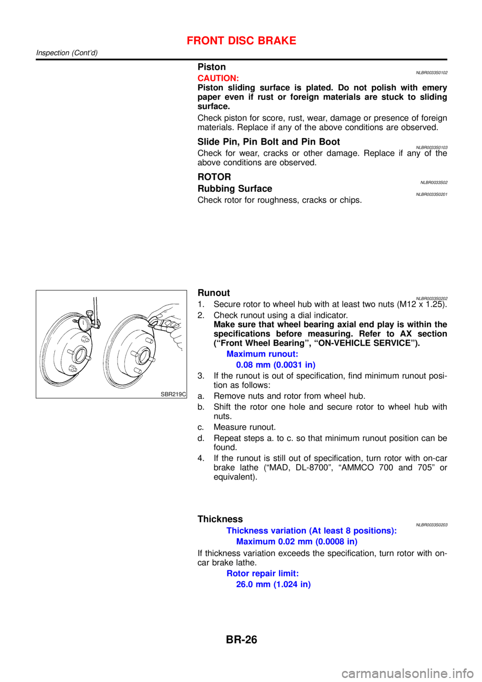
RunoutNLBR0033S02021. Secure rotor to wheel hub with at least two nuts (M12 x 1.25).
2. Check runout using a dial indicator.
Make sure that wheel bearing axial end play is within the
specifications before measuring. Refer to AX section
(“Front Wheel Bearing”,“ON-VEHICLE SERVICE”).
Maximum runout:
0.08 mm (0.0031 in)
3. If the runout is out of specification, find minimum runout posi-
tion as follows:
a. Remove nuts and rotor from wheel hub.
b. Shift the rotor one hole and secure rotor to wheel hub with
nuts.
c. Measure runout.
d. Repeat steps a. to c. so that minimum runout position can be
found.
4. If the runout is still out of specification, turn rotor with on-car
brake lathe (“MAD, DL-8700”,“AMMCO 700 and 705”or
equivalent).
ThicknessNLBR0033S0203Thickness variation (At least 8 positions):
Maximum 0.02 mm (0.0008 in)
If thickness variation exceeds the specification, turn rotor with on-
car brake lathe.
Rotor repair limit:
26.0 mm (1.024 in)
FRONT DISC BRAKE
Inspection (Cont’d)
BR-26
Page 264 of 3051
SBR574
AssemblyNLBR00341. Insert piston seal into groove on cylinder body.
2. With piston boot fitted to piston, insert piston boot into groove
on cylinder body and install piston.
3. Properly secure piston boot.
SBR980B
InstallationNLBR0035CAUTION:
+Refill with new brake fluid“DOT 4”.
+Never reuse drained brake fluid.
1. Install brake hose to caliper securely.
2. Install all parts and secure all bolts.
3. Bleed air. Refer to“Bleeding Brake System”, BR-8.
FRONT DISC BRAKE
Assembly
BR-27
Page 269 of 3051
Pin and Pin BootNLBR0041S0104Check for wear, cracks or other damage.
Replace if any of the above conditions are observed.
SBR219C
ROTORNLBR0041S02Rubbing SurfaceNLBR0041S0201Check rotor for roughness, cracks or chips.
RunoutNLBR0041S02021. Secure rotor to wheel hub with two nuts (M12 x 1.25).
2. Check runout using a dial indicator.
Make sure that axial end play is within the specifications
before measuring. Refer to AX section (“REAR WHEEL
BEARING”,“On-vehicle Service”).
3. Change relative positions of rotor and wheel hub so that runout
is minimized.
Maximum runout:
0.07 mm (0.0028 in)
ThicknessNLBR0041S0203Rotor repair limit:
Standard thickness
10 mm (0.39 in)
Minimum thickness
9 mm (0.35 in)
Thickness variation (At least 8 portions)
Maximum 0.02 mm (0.0008 in)
NBR367
AssemblyNLBR00421. Insert cam with depression facing towards open end of cylin-
der.
REAR DISC BRAKE (CAM & STRUT TYPE)
Inspection (Cont’d)
BR-32
Page 272 of 3051
NBR375
InstallationNLBR0043CAUTION:
+Refill with new brake fluid“DOT 4”.
+Never reuse drained brake fluid.
1. Install caliper assembly.
+As shown in the figure, align the piston’s concave to the pad’s
convex, then install the cylinder body to the torque member.
2. Install brake hose to caliper securely.
3. Install all parts and secure all bolts.
4. Bleed air. Refer to“Bleeding Brake System”, BR-8 and“Air
Bleeding Procedure”, CL-10.
REAR DISC BRAKE (CAM & STRUT TYPE)
Installation
BR-35
Page 276 of 3051

SBR219C
ROTORNLBR0154S02Rubbing SurfaceNLBR0154S0201Check rotor for roughness, cracks or chips.
RunoutNLBR0154S02021. Secure rotor to wheel hub with two nuts (M12 x 1.25).
2. Check runout using a dial indicator.
Make sure that axial end play is within the specifications
before measuring. Refer to AX section (“REAR WHEEL
BEARING”,“On-vehicle Service”).
3. Change relative positions of rotor and wheel hub so that runout
is minimized.
Maximum runout:
0.07 mm (0.0028 in)
ThicknessNLBR0154S0203Rotor repair limit:
Standard thickness
10 mm (0.39 in)
Minimum thickness
9 mm (0.35 in)
Thickness variation (At least 8 portions)
Maximum 0.02 mm (0.0008 in)
NBR374
NBR375
InstallationNLBR0156CAUTION:
+Refill with new brake fluid“DOT 4”.
+Never reuse drained brake fluid.
+Do not drain (factory) filled brake fluid from (new) caliper
assemblies.
1. Install caliper assembly.
+As shown in the figure, align the piston’s concave to the pad’s
convex, then install the cylinder body to the torque member.
2. Remove the plug from the cylinder body and brake hose.
CAUTION:
Care should be taken as not to let:
+Air enter the cylinder body and brake hose.
+Brake fluid spill from the cylinder body and brake hose.
3. Install brake hose to caliper securely.
4. Install all parts and secure all bolts.
5. Bleed air. Refer to“Bleeding Brake System”, BR-8 and“Air
Bleeding Procedure”, CL-10.
REAR DISC BRAKE (BALL & RAMP TYPE)
Inspection (Cont’d)
BR-39
Page 277 of 3051
ComponentsNLBR0044
NBR368
SBR897D
Removal and InstallationNLBR00451. To remove parking brake cable, first remove center console.
2. Disconnect warning lamp switch connector.
3. Remove adjusting nut.
4. Remove bolts and nuts securing parking brake cable.
5. Remove parking brake device.
SBR025D
6. Remove lock plate and disconnect cable.
InspectionNLBR00461. Check control lever for wear or other damage. Replace if nec-
essary.
2. Check wires for discontinuity or deterioration. Replace if nec-
essary.
3. Check warning lamp and switch. Replace if necessary.
4. Check parts at each connecting portion and, if found deformed
or damaged, replace.
PARKING BRAKE CONTROL
Components
BR-40