Page 295 of 3051

CONSULT-IINLBR0092CONSULT-II APPLICATION TO ABSNLBR0092S01
ITEMSELF-DIAGNOSTIC
RESULTSDATA MONITOR ACTIVE TEST
Front right wheel sensor X X—
Front left wheel sensor X X—
Rear right wheel sensor X X—
Rear left wheel sensor X X—
Stop lamp switch—X—
Front right inlet solenoid valve X X X
Front right outlet solenoid valve X X X
Front left inlet solenoid valve X X X
Front left outlet solenoid valve X X X
Rear right inlet solenoid valve X X X
Rear right outlet solenoid valve X X X
Rear left inlet solenoid valve X X X
Rear left outlet solenoid valve X X X
Actuator solenoid valve relay X X—
Actuator motor relay
(ABS MOTOR is shown on the ACTIVE TEST
screen.)XXX
ABS warning lamp—X—
Battery voltage X X—
Control unit X——
X: Applicable
—: Not applicable
ECU (ABS CONTROL UNIT) PART NUMBER MODENLBR0092S02Ignore the ECU part number displayed in the ECU PART NUMBER MODE. Refer to parts catalog to order
the ABS actuator and electric unit.
NBR371
CONSULT-II Inspection ProcedureNLBR0093SELF-DIAGNOSIS PROCEDURENLBR0093S011. Turn ignition switch OFF.
2. Connect CONSULT-II to data link connector.
3. Start engine.
4. Drive vehicle over 30 km/h (19 MPH) for at least one minute.
ON BOARD DIAGNOSTIC SYSTEM DESCRIPTIONABS
CONSULT-II
BR-58
Page 338 of 3051

Removal and InstallationNLBT0004+When removing or installing hood, place a cloth or other padding on hood. This prevents vehicle body from
being scratched.
+Bumper fascia is made of plastic. Do not use excessive force and be sure to keep oil away from it.
+Hood adjustment: Adjust at hinge portion.
+Hood lock adjustment: After adjusting, check hood lock control operation. Apply a coat of grease to hood
locks engaging mechanism.
+Hood opener: Do not attempt to bend cable forcibly. Doing so increases effort required to unlock hood.
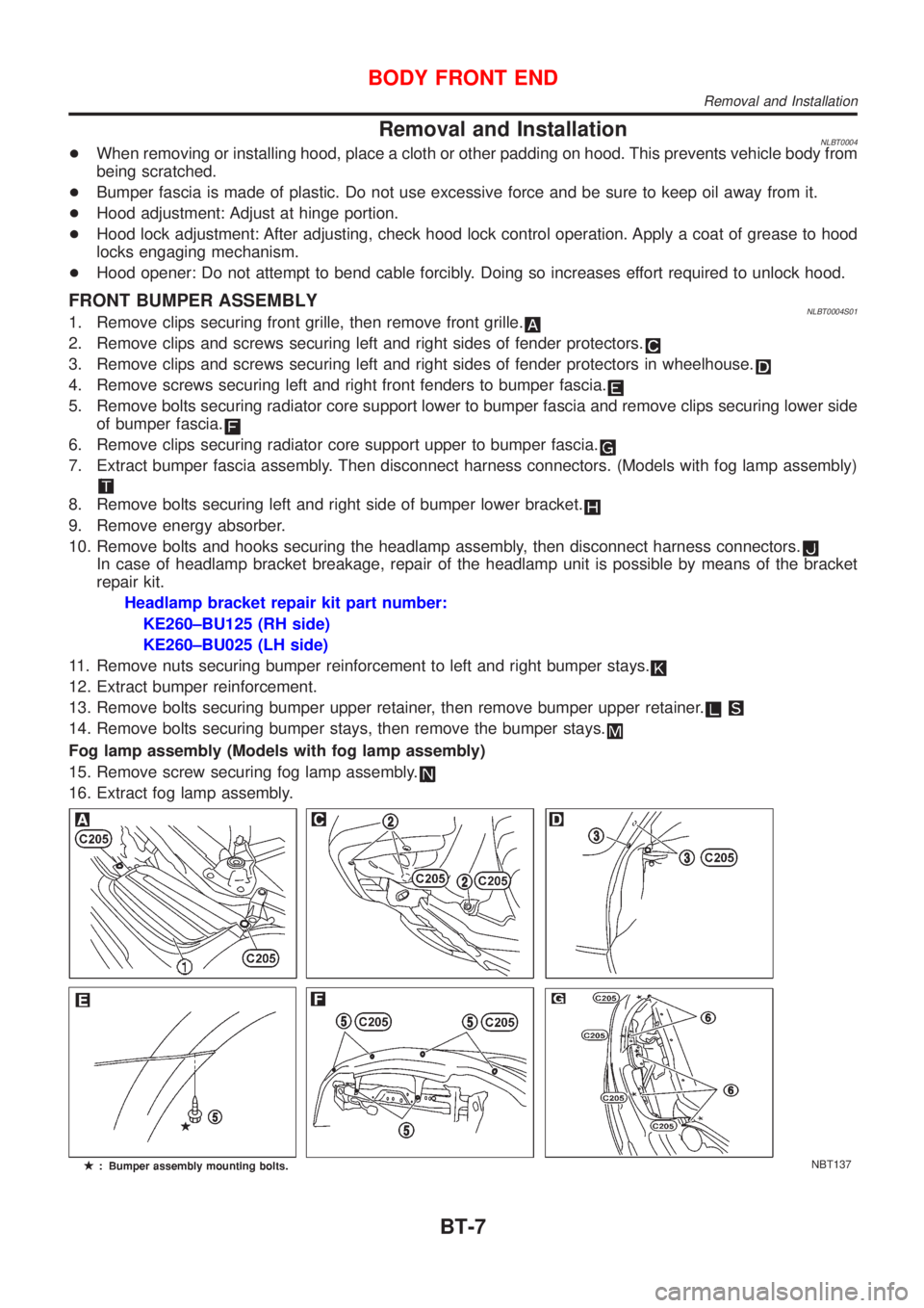
FRONT BUMPER ASSEMBLYNLBT0004S011. Remove clips securing front grille, then remove front grille.
2. Remove clips and screws securing left and right sides of fender protectors.
3. Remove clips and screws securing left and right sides of fender protectors in wheelhouse.
4. Remove screws securing left and right front fenders to bumper fascia.
5. Remove bolts securing radiator core support lower to bumper fascia and remove clips securing lower side
of bumper fascia.
6. Remove clips securing radiator core support upper to bumper fascia.
7. Extract bumper fascia assembly. Then disconnect harness connectors. (Models with fog lamp assembly)
8. Remove bolts securing left and right side of bumper lower bracket.
9. Remove energy absorber.
10. Remove bolts and hooks securing the headlamp assembly, then disconnect harness connectors.
In case of headlamp bracket breakage, repair of the headlamp unit is possible by means of the bracket
repair kit.
Headlamp bracket repair kit part number:
KE260±BU125 (RH side)
KE260±BU025 (LH side)
11. Remove nuts securing bumper reinforcement to left and right bumper stays.
12. Extract bumper reinforcement.
13. Remove bolts securing bumper upper retainer, then remove bumper upper retainer.
14. Remove bolts securing bumper stays, then remove the bumper stays.
Fog lamp assembly (Models with fog lamp assembly)
15. Remove screw securing fog lamp assembly.
16. Extract fog lamp assembly.
NBT137
BODY FRONT END
Removal and Installation
BT-7
Page 341 of 3051

Removal and InstallationNLBT0034+When removing or installing back door, place a cloth or other padding on back door. This prevents vehicle
body from being scratched.
+Bumper fascia is made of plastic. Do not use excessive force and be sure to keep oil away from it.
+Back door adjustment: Adjust at hinge-back door portion for proper back door fit.
+Back door lock system adjustment: Adjust striker so that it is in the center of the lock. After adjustment,
check back door lock operation.
+After installation, make sure that back door and fuel filler lid open smoothly.
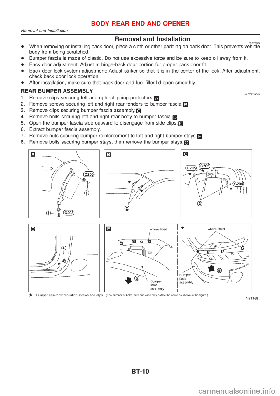
REAR BUMPER ASSEMBLYNLBT0034S011. Remove clips securing left and right chipping protectors.
2. Remove screws securing left and right rear fenders to bumper fascia.
3. Remove clips securing bumper fascia assembly.
4. Remove bolts securing left and right rear body to bumper fascia.
5. Open the bumper fascia side outward to disengage from side clips.
6. Extract bumper fascia assembly.
7. Remove nuts securing bumper reinforcement to left and right bumper stays.
8. Remove bolts securing bumper stays, then remove the bumper stays.
NBT168
BODY REAR END AND OPENER
Removal and Installation
BT-10
Page 345 of 3051
Front Door Glass=NLBT0007+Make sure that door glass is positioned in glass run groove.
+Make sure that there is no abnormality when door glass is
raised or lowered.
FRONT DOOR GLASS AND REGULATORNLBT0007S01
NBT086
+For removal of front door finisher, refer to ªDOOR TRIMº,
BT-32.
+Remove sealing screen.
NBT087
1. Using power window main switch, raise or lower door glass
until carrier plate securing bolts are visible.
2. Remove bolts securing carrier plate.
DOOR
Front Door Glass
BT-14
Page 346 of 3051

NBT088
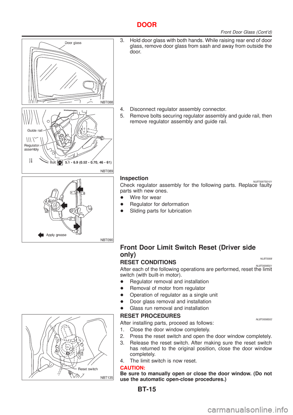
3. Hold door glass with both hands. While raising rear end of door
glass, remove door glass from sash and away from outside the
door.
NBT089
4. Disconnect regulator assembly connector.
5. Remove bolts securing regulator assembly and guide rail, then
remove regulator assembly and guide rail.
NBT090
InspectionNLBT0007S0101Check regulator assembly for the following parts. Replace faulty
parts with new ones.
+Wire for wear
+Regulator for deformation
+Sliding parts for lubrication
Front Door Limit Switch Reset (Driver side
only)
NLBT0008RESET CONDITIONSNLBT0008S01After each of the following operations are performed, reset the limit
switch (with built-in motor).
+Regulator removal and installation
+Removal of motor from regulator
+Operation of regulator as a single unit
+Door glass removal and installation
+Glass run removal and installation
NBT135
RESET PROCEDURESNLBT0008S02After installing parts, proceed as follows:
1. Close the door window completely.
2. Press the reset switch and open the door window completely.
3. Release the reset switch. After making sure the reset switch
has returned to the original position, close the door window
completely.
4. The limit switch is now reset.
CAUTION:
Be sure to manually open or close the door window. (Do not
use the automatic open-close procedures.)
DOOR
Front Door Glass (Cont'd)
BT-15
Page 347 of 3051
Rear Door GlassNLBT0009+Make sure that door glass is positioned in glass run groove.
+Make sure that there is no abnormality when door glass is
raised or lowered.
REAR DOOR GLASS AND REGULATORNLBT0009S01
NBT092
+For removal of rear door finisher, refer to ªDOOR TRIMº,
BT-32.
+For removal of door outside molding, refer to ªEXTERIORº,
BT-38.
+Remove sealing screen.
NBT093
1. Remove bolts securing lower sash rear, then remove lower
sash rear.
2. Using power window main switch, raise or lower door glass
until carrier plate securing bolts are visible.
3. Remove bolts securing main channel.
DOOR
Rear Door Glass
BT-16
Page 348 of 3051
NBT094
4. Disconnect regulator assembly connector.
5. Remove bolts securing regulator assembly, then remove regu-
lator assembly.
NBT095
6. Remove corner inner cover.
NBT096
7. Remove nut securing lower sash rear.
NBT097
8. Remove bolt securing under of lower sash rear.
9. Remove door glass from glass run and away from outside the
door.
NBT136
InspectionNLBT0009S0101Check regulator assembly for the following parts. Replace faulty
parts with new ones.
+Wire for wear
+Regulator for deformation
+Sliding parts for lubrication
DOOR
Rear Door Glass (Cont'd)
BT-17
Page 349 of 3051
Front Door LockNLBT0010
NBT098
+For removal of front door finisher, refer to ªDOOR TRIMº,
BT-32.
+Remove sealing screen.
SBT978
OUTSIDE HANDLE ROD ADJUSTMENTNLBT0010S02Rotate rod holder so that rod-to-holder clearance is adjusted as
shown in the figure at left.
CAUTION:
Make sure that rod-to-holder clearance is not ª0º mm (0 in),
and that rod is not held pressed.
NBT099
REMOVALNLBT0010S03+For removal of front door finisher, refer to ªDOOR TRIMº,
BT-32.
+Remove sealing screen.
+For removal of front door glass, refer to ªFront Door Glassº,
BT-14.
1. Remove lower rear sash (unitized with glass run) securing
bolts. Remove lower rear sash from door panel and away from
door lock.
DOOR
Front Door Lock
BT-18