Page 2925 of 3051

SRS871
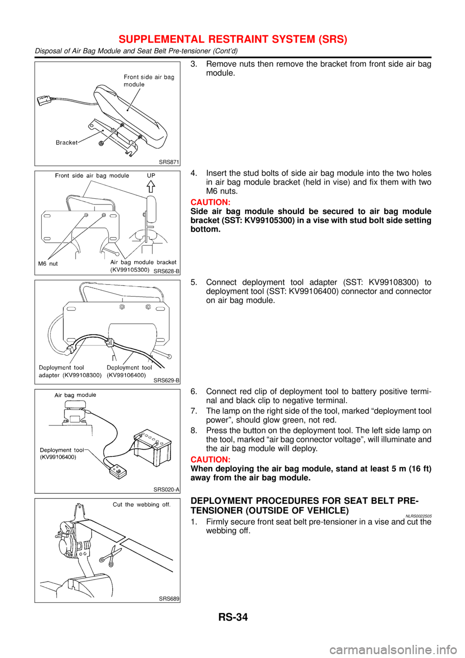
3. Remove nuts then remove the bracket from front side air bag
module.
SRS628-B
4. Insert the stud bolts of side air bag module into the two holes
in air bag module bracket (held in vise) and fix them with two
M6 nuts.
CAUTION:
Side air bag module should be secured to air bag module
bracket (SST: KV99105300) in a vise with stud bolt side setting
bottom.
SRS629-B
5. Connect deployment tool adapter (SST: KV99108300) to
deployment tool (SST: KV99106400) connector and connector
on air bag module.
SRS020-A
6. Connect red clip of deployment tool to battery positive termi-
nal and black clip to negative terminal.
7. The lamp on the right side of the tool, marked“deployment tool
power”, should glow green, not red.
8. Press the button on the deployment tool. The left side lamp on
the tool, marked“air bag connector voltage”, will illuminate and
the air bag module will deploy.
CAUTION:
When deploying the air bag module, stand at least 5 m (16 ft)
away from the air bag module.
SRS689
DEPLOYMENT PROCEDURES FOR SEAT BELT PRE-
TENSIONER (OUTSIDE OF VEHICLE)
NLRS0022S051. Firmly secure front seat belt pre-tensioner in a vise and cut the
webbing off.
SUPPLEMENTAL RESTRAINT SYSTEM (SRS)
Disposal of Air Bag Module and Seat Belt Pre-tensioner (Cont’d)
RS-34
Page 2928 of 3051

Trouble Diagnoses Introduction=NLRS0043CAUTION:
+Do not use electrical test equipment on any circuit related to the SRS unless instructed to in this
Service Manual. Spiral cable and wiring harnesses covered with yellow insulation tape either just
before the harness connectors or for the complete harness are related to the SRS.
+Do not attempt to repair, splice or modify the SRS wiring harness. If the harness is damaged,
replace it with a new one.
+Keep ground portion clean.
DIAGNOSIS FUNCTIONNLRS0043S01The SRS self-diagnosis results can be read by using“AIR BAG”warning lamp and/or CONSULT-II. The read-
ing of these results is accomplished using one of two modes—“User mode”and“Diagnosis mode”.
The User mode is exclusively prepared for the customer (driver). This mode warns the driver of a system
malfunction through the operation of the“AIR BAG”warning lamp.
The Diagnosis mode allows the technician to locate and inspect the malfunctioning part.
The mode applications for the“AIR BAG”warning lamp and CONSULT-II are as follows:
User mode Diagnosis mode Display type
“AIR BAG”warning lamp X X ON-OFF operation
CONSULT-II—X Monitoring
NOTE:
Seat belt pre-tensioner malfunction is indicated by“AIR BAG”warning lamp.
DIAGNOSIS MODE FOR CONSULT-IINLRS0043S02+“SELF-DIAG [CURRENT]”
A current Self-diagnosis result (also indicated by the number of warning lamp flashes in the Diagnosis
mode) is displayed on the CONSULT-II screen in real time. This refers to a malfunctioning part requiring
repairs.
+“SELF-DIAG [PAST]”
Diagnosis results previously stored in the memory are displayed on the CONSULT-II screen. The stored
results are not erased until memory erasing is executed.
+“TROUBLE DIAG RECORD”
With TROUBLE DIAG RECORD, diagnosis results previously erased by a reset operation can be displayed
on the CONSULT-II screen.
+“ECU DISCRIMINATED NO.”
The diagnosis sensor unit for each vehicle model is assigned with its own, individual classification num-
ber (refer to the table below). This number will be displayed on the CONSULT-II screen. When replacing
the diagnosis sensor unit, refer to the part number for the compatibility. After installation, replacement with
a correct unit can be checked by confirming this classification number on the CONSULT-II screen.
For NISSAN MODEL V10, the diagnosis sensor unit classification numbers are as follows:
MODEL ECU DISCRIMINATED NO.
Models with single air bag and seat belt pre-tensioner A910
Models with dual air bags and seat belt pre-tensioner A911
Models with dual air bags, side air bag and seat belt pre-tensioner A912
SUPPLEMENTAL RESTRAINT SYSTEM (SRS)
Trouble Diagnoses Introduction
RS-37
Page 2958 of 3051
Part SRS is activated SRS is NOT activated
Harness and Connec-
tors1. Check connectors for poor connection, damage, and terminals for deformities.
2. Check harness for binding, chafing, cuts, or deformities.
3. If no damage is found, reinstall the harness and connectors.
4. Damaged—REPLACE damaged section of harness. Do not attempt to repair, splice or modify any SRS
harness.
Instrument panel 1. When passenger air bag inflates, check the following points for bending, deformities or cracks.
+Opening portion for front passenger air bag
NRS118
+Front passenger air bag module brackets
NRS119
+The portions securing the instrument panel
NRS120
2. If no damage is found, reinstall the instrument panel.
3. If damaged—REPLACE the instrument panel with bolts.
SUPPLEMENTAL RESTRAINT SYSTEM (SRS)
Collision Diagnosis (Cont’d)
RS-67
Page 2982 of 3051
SEL015Z
Brush Spring CheckNLSC0019S0302Check brush spring pressure with brush spring detached from
brush.
Spring pressure (with new brush):
Refer to SDS (SC-34).
+Not within the specified values ... Replace.
SEL016Z
Brush HolderNLSC0019S03031. Perform insulation test between brush holder (positive side)
and its base (negative side).
+Continuity exists. ... Replace.
2. Check brush to see if it moves smoothly.
+If brush holder is bent, replace it; if sliding surface is dirty,
clean.
SEL018Z
YOKE CHECKNLSC0019S04Magnet is secured to yoke by bonding agent. Check magnet to see
that it is secured to yoke and for any cracks. Replace malfunction-
ing parts as an assembly.
CAUTION:
Do not clamp yoke in a vice or strike it with a hammer.
STARTING SYSTEM
Inspection (Cont’d)
SC-21
Page 3006 of 3051

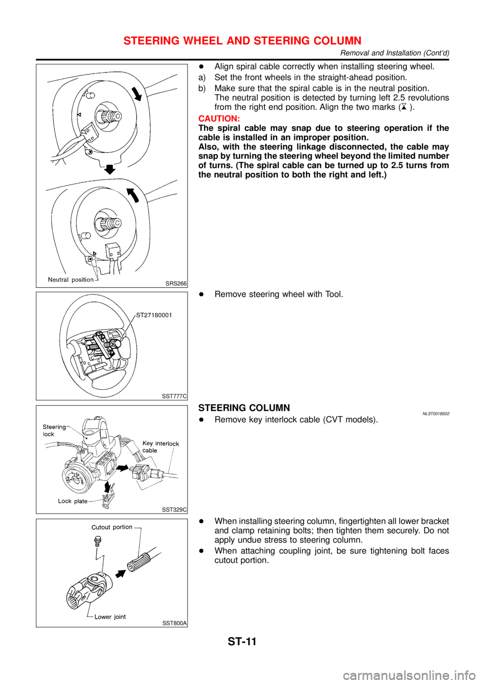
SRS266
+Align spiral cable correctly when installing steering wheel.
a) Set the front wheels in the straight-ahead position.
b) Make sure that the spiral cable is in the neutral position.
The neutral position is detected by turning left 2.5 revolutions
from the right end position. Align the two marks (
).
CAUTION:
The spiral cable may snap due to steering operation if the
cable is installed in an improper position.
Also, with the steering linkage disconnected, the cable may
snap by turning the steering wheel beyond the limited number
of turns. (The spiral cable can be turned up to 2.5 turns from
the neutral position to both the right and left.)
SST777C
+Remove steering wheel with Tool.
SST329C
STEERING COLUMNNLST0018S02+Remove key interlock cable (CVT models).
SST800A
+When installing steering column, fingertighten all lower bracket
and clamp retaining bolts; then tighten them securely. Do not
apply undue stress to steering column.
+When attaching coupling joint, be sure tightening bolt faces
cutout portion.
STEERING WHEEL AND STEERING COLUMN
Removal and Installation (Cont’d)
ST-11
Page 3014 of 3051
Be careful not to damage spacer ring during installation
SST867C
2. Tighten outer socket lock nut.
Tie-rod length“L”:
Refer to SDS, ST-28.
SST086BA
3. Measure rack stroke.
Rack stroke“S”:
Refer to SDS, ST-28.
SST967A
4. Before installing boot, coat the contact surfaces between boot
and tie-rod with grease.
SST868C
5. Install boot bands.
+Securely install boot band to boot groove and clinch the root
section of the trapezoidal area.
+Make sure that there is a clearance of 3.5 mm (0.138 in) or less
at the clinched section of the boot band. Refer to the Figure at
left.
POWER STEERING GEAR AND LINKAGE
Assembly (Cont’d)
ST-19
Page 3046 of 3051

SRA695A
SSU038
REMOVALNLSU0031S01CAUTION:
+Before removing the rear suspension assembly, discon-
nect the ABS wheel sensor from the assembly. Failure to
do so may result in damage to the sensor wires and the
sensor becoming inoperative.
+Remove suspension assembly.
1. Disconnect brake hydraulic lines and parking brake cable at
toggle lever. (Models with drum brakes.)
+Drain brake fluid before disconnecting brake lines.
2. Disconnect parking brake cable from caliper and remove brake
caliper and rotor. (Models with disc brakes.)
Suspend caliper assembly with wire so as not to stretch
brake hose.
Be careful not to depress brake pedal, or piston will pop
out.
Make sure brake hose is not twisted.
3. Using a transmission jack, raise torsion beam a little, and
remove nuts and bolts from the trailing arm, shock absorber
assembly (lower side) and lateral link (Body side).
4. Lower transmission jack, and remove suspension.
5. Remove strut securing nuts (upper side). Then pull out strut
assembly.
SRA697A
INSTALLATIONNLSU0031S02+Install suspension assembly.
CAUTION:
Refill with new brake fluid“DOT 4”.
Never reuse drained brake fluid.
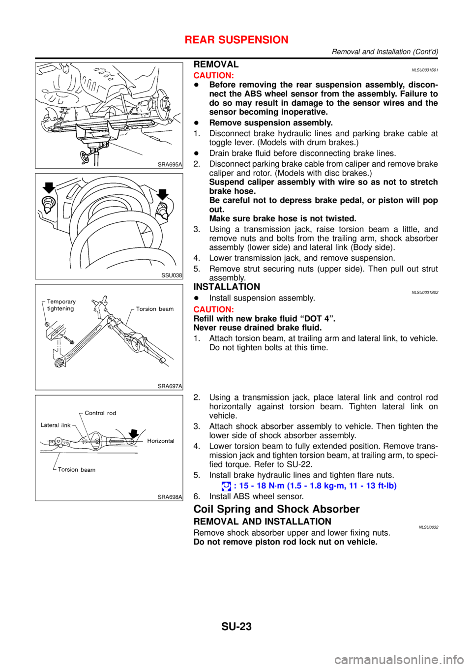
1. Attach torsion beam, at trailing arm and lateral link, to vehicle.
Do not tighten bolts at this time.
SRA698A
2. Using a transmission jack, place lateral link and control rod
horizontally against torsion beam. Tighten lateral link on
vehicle.
3. Attach shock absorber assembly to vehicle. Then tighten the
lower side of shock absorber assembly.
4. Lower torsion beam to fully extended position. Remove trans-
mission jack and tighten torsion beam, at trailing arm, to speci-
fied torque. Refer to SU-22.
5. Install brake hydraulic lines and tighten flare nuts.
:15-18N·m (1.5 - 1.8 kg-m, 11 - 13 ft-lb)
6. Install ABS wheel sensor.
Coil Spring and Shock Absorber
REMOVAL AND INSTALLATIONNLSU0032Remove shock absorber upper and lower fixing nuts.
Do not remove piston rod lock nut on vehicle.
REAR SUSPENSION
Removal and Installation (Cont’d)
SU-23