2001 NISSAN ALMERA TINO ECU
[x] Cancel search: ECUPage 2465 of 3051
JEM158G
SEM301G
3. Heat cylinder head to 110 to 120ÉC (230 to 248ÉF) by soaking
in heated oil.
4. Sufficiently cool valve seat with dry ice. Force fit valve seat into
cylinder head.
WARNING:
Do not touch cold valve seat with your bare hands.
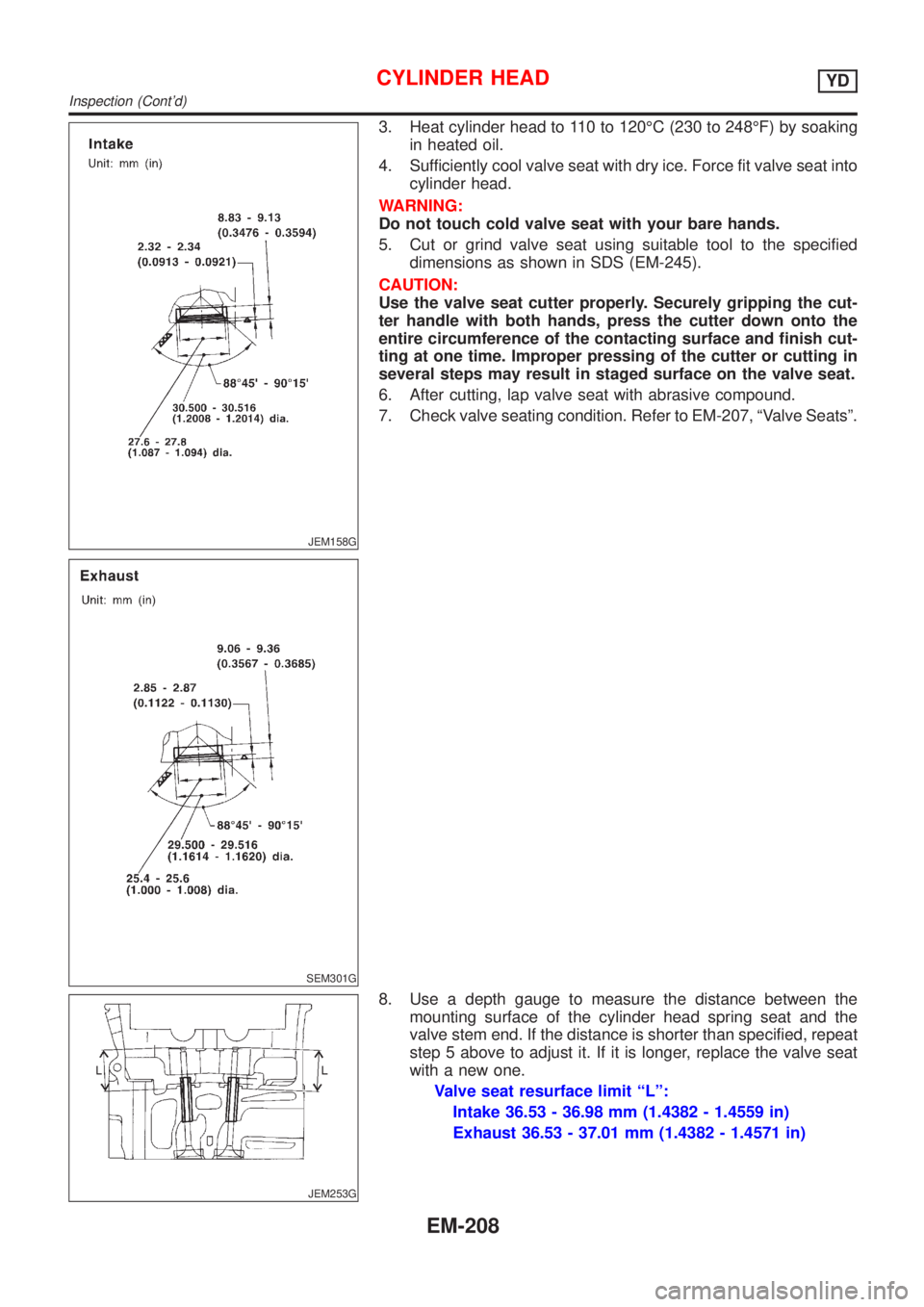
5. Cut or grind valve seat using suitable tool to the specified
dimensions as shown in SDS (EM-245).
CAUTION:
Use the valve seat cutter properly. Securely gripping the cut-
ter handle with both hands, press the cutter down onto the
entire circumference of the contacting surface and finish cut-
ting at one time. Improper pressing of the cutter or cutting in
several steps may result in staged surface on the valve seat.
6. After cutting, lap valve seat with abrasive compound.
7. Check valve seating condition. Refer to EM-207, ªValve Seatsº.
JEM253G
8. Use a depth gauge to measure the distance between the
mounting surface of the cylinder head spring seat and the
valve stem end. If the distance is shorter than specified, repeat
step 5 above to adjust it. If it is longer, replace the valve seat
with a new one.
Valve seat resurface limit ªLº:
Intake 36.53 - 36.98 mm (1.4382 - 1.4559 in)
Exhaust 36.53 - 37.01 mm (1.4382 - 1.4571 in)
CYLINDER HEADYD
Inspection (Cont'd)
EM-208
Page 2470 of 3051
JEM173G
CAMSHAFT INSTALLATIONNLEM0067S071. Install valve lifters and adjusting shims.
+Install in the correct locations (the same places as before
removal).
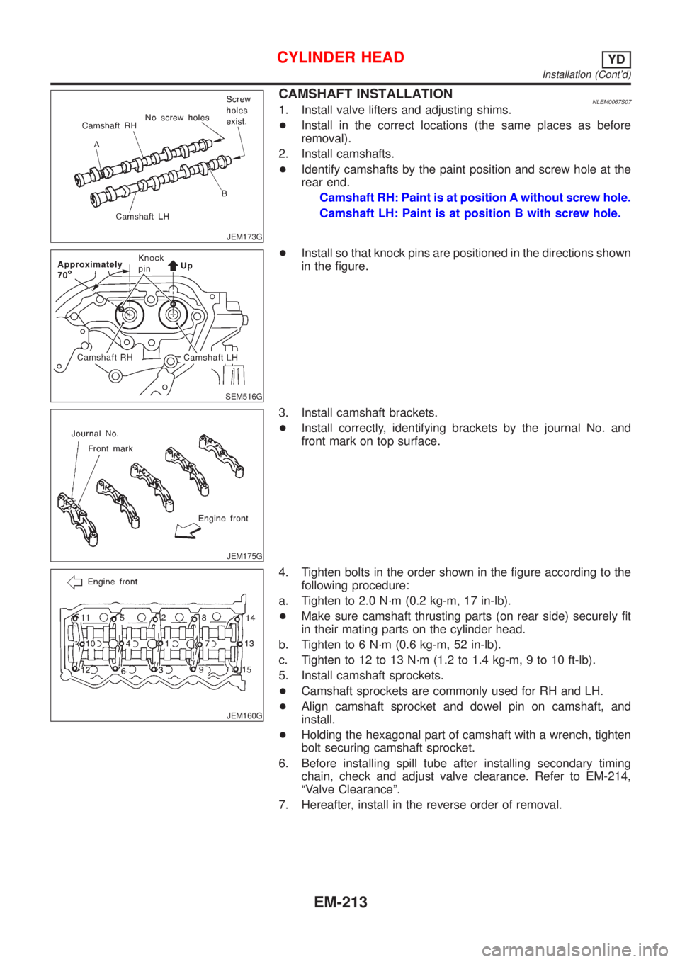
2. Install camshafts.
+Identify camshafts by the paint position and screw hole at the
rear end.
Camshaft RH: Paint is at position A without screw hole.
Camshaft LH: Paint is at position B with screw hole.
SEM516G
+Install so that knock pins are positioned in the directions shown
in the figure.
JEM175G
3. Install camshaft brackets.
+Install correctly, identifying brackets by the journal No. and
front mark on top surface.
JEM160G
4. Tighten bolts in the order shown in the figure according to the
following procedure:
a. Tighten to 2.0 N´m (0.2 kg-m, 17 in-lb).
+Make sure camshaft thrusting parts (on rear side) securely fit
in their mating parts on the cylinder head.
b. Tighten to 6 N´m (0.6 kg-m, 52 in-lb).
c. Tighten to 12 to 13 N´m (1.2 to 1.4 kg-m, 9 to 10 ft-lb).
5. Install camshaft sprockets.
+Camshaft sprockets are commonly used for RH and LH.
+Align camshaft sprocket and dowel pin on camshaft, and
install.
+Holding the hexagonal part of camshaft with a wrench, tighten
bolt securing camshaft sprocket.
6. Before installing spill tube after installing secondary timing
chain, check and adjust valve clearance. Refer to EM-214,
ªValve Clearanceº.
7. Hereafter, install in the reverse order of removal.
CYLINDER HEADYD
Installation (Cont'd)
EM-213
Page 2476 of 3051
crankshaft position sensor (TDC sensor) from the assem-
bly.
+Always pay extra attention not to damage edge of crank-
shaft position sensor (TDC sensor) or ring gear teeth.
REMOVALNLEM0069S011. Remove engine undercover, and hood for hoisting.
2. Drain coolant from both cylinder block and radiator. Refer to
LC-59, ªChanging Engine Coolantº.
3. Remove the following parts:
+Battery
+RH and LH front wheels
+RH and LH splash covers (combined with undercover)
+Auxiliary belts
+Alternator
+Alternator brackets
+Radiator and cooling fan
+Engine cover
+Air ducts and air cleaner case
LH side of engine room:
4. Disconnect all harnesses and grounds that are connected to
components on vehicle.
5. Disconnect vacuum hose on vacuum pump side.
6. Disconnect fuel feed and fuel return hoses on engine side.
+Immediately put blind plugs into the openings to prevent
fuel from flowing out.
7. Disconnect heater hose. Plug opening of hose to prevent cool-
ant from flowing out.
RH side of engine room:
8. Remove air conditioner compressor from brackets and move
it toward vehicle side. Secure compressor on vehicle side with
rope.
Vehicle underside:
9. Remove exhaust front tube.
10. Disconnect two hoses from power steering pump and plug to
stop fluid.
11. Remove M/T control rod and support rod.
12. Remove ABS wheel sensor, and temporarily hang brake cali-
per with rope on vehicle side.
13. Remove RH and LH drive shafts.
SEM499G
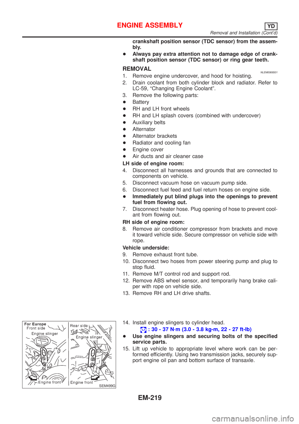
14. Install engine slingers to cylinder head.
: 30 - 37 N´m (3.0 - 3.8 kg-m, 22 - 27 ft-lb)
+Use engine slingers and securing bolts of the specified
service parts.
15. Lift up vehicle to appropriate level where work can be per-
formed efficiently. Using two transmission jacks, securely sup-
port engine oil pan and bottom surface of transaxle.
ENGINE ASSEMBLYYD
Removal and Installation (Cont'd)
EM-219
Page 2477 of 3051
SEM189G
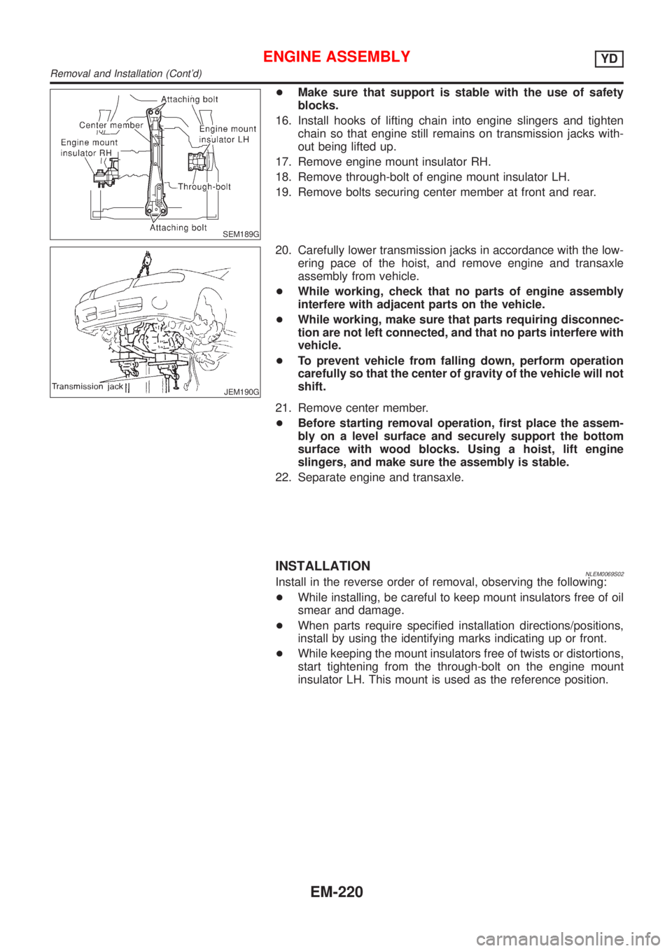
+Make sure that support is stable with the use of safety
blocks.
16. Install hooks of lifting chain into engine slingers and tighten
chain so that engine still remains on transmission jacks with-
out being lifted up.
17. Remove engine mount insulator RH.
18. Remove through-bolt of engine mount insulator LH.
19. Remove bolts securing center member at front and rear.
JEM190G
20. Carefully lower transmission jacks in accordance with the low-
ering pace of the hoist, and remove engine and transaxle
assembly from vehicle.
+While working, check that no parts of engine assembly
interfere with adjacent parts on the vehicle.
+While working, make sure that parts requiring disconnec-
tion are not left connected, and that no parts interfere with
vehicle.
+To prevent vehicle from falling down, perform operation
carefully so that the center of gravity of the vehicle will not
shift.
21. Remove center member.
+Before starting removal operation, first place the assem-
bly on a level surface and securely support the bottom
surface with wood blocks. Using a hoist, lift engine
slingers, and make sure the assembly is stable.
22. Separate engine and transaxle.
INSTALLATIONNLEM0069S02Install in the reverse order of removal, observing the following:
+While installing, be careful to keep mount insulators free of oil
smear and damage.
+When parts require specified installation directions/positions,
install by using the identifying marks indicating up or front.
+While keeping the mount insulators free of twists or distortions,
start tightening from the through-bolt on the engine mount
insulator LH. This mount is used as the reference position.
ENGINE ASSEMBLYYD
Removal and Installation (Cont'd)
EM-220
Page 2479 of 3051
Removal and InstallationNLEM0071CAUTION:
+When installing bearings, pistons, or other sliding parts,
lubricate contacting surfaces with new engine oil.
+Place removed parts such as bearings and bearing caps
in their proper order and direction.
+When installing connecting rod nuts, and main bearing
cap bolts, apply new engine oil to threads and seating
surfaces.
+Do not allow any magnetic materials to contact the signal
plate of flywheel.
+Do not remove the signal plate at back.
+Do not place the signal plate side facing under.
+Handle with care so as not to damage the signal plate
[especially four places on protrusions for signal of crank
position sensor (TDC sensor)].
DisassemblyNLEM0072PISTON AND CRANKSHAFTNLEM0072S011. Remove engine. Refer to ªENGINE ASSEMBLYº, ªRemoval
and Installationº, EM-218.
2. Place engine on a work stand.
a. Remove flywheel.
+Hold ring gear with ring gear stopper (KV10105630,
KV10105610). Then, loosen securing bolts with TORX socket
(size: Q8 E20, Commercial Service Tool) and remove them.
As an alternative method, hold the crankshaft pulley with a
pulley holder (SST) to remove the flywheel.
JEM192G
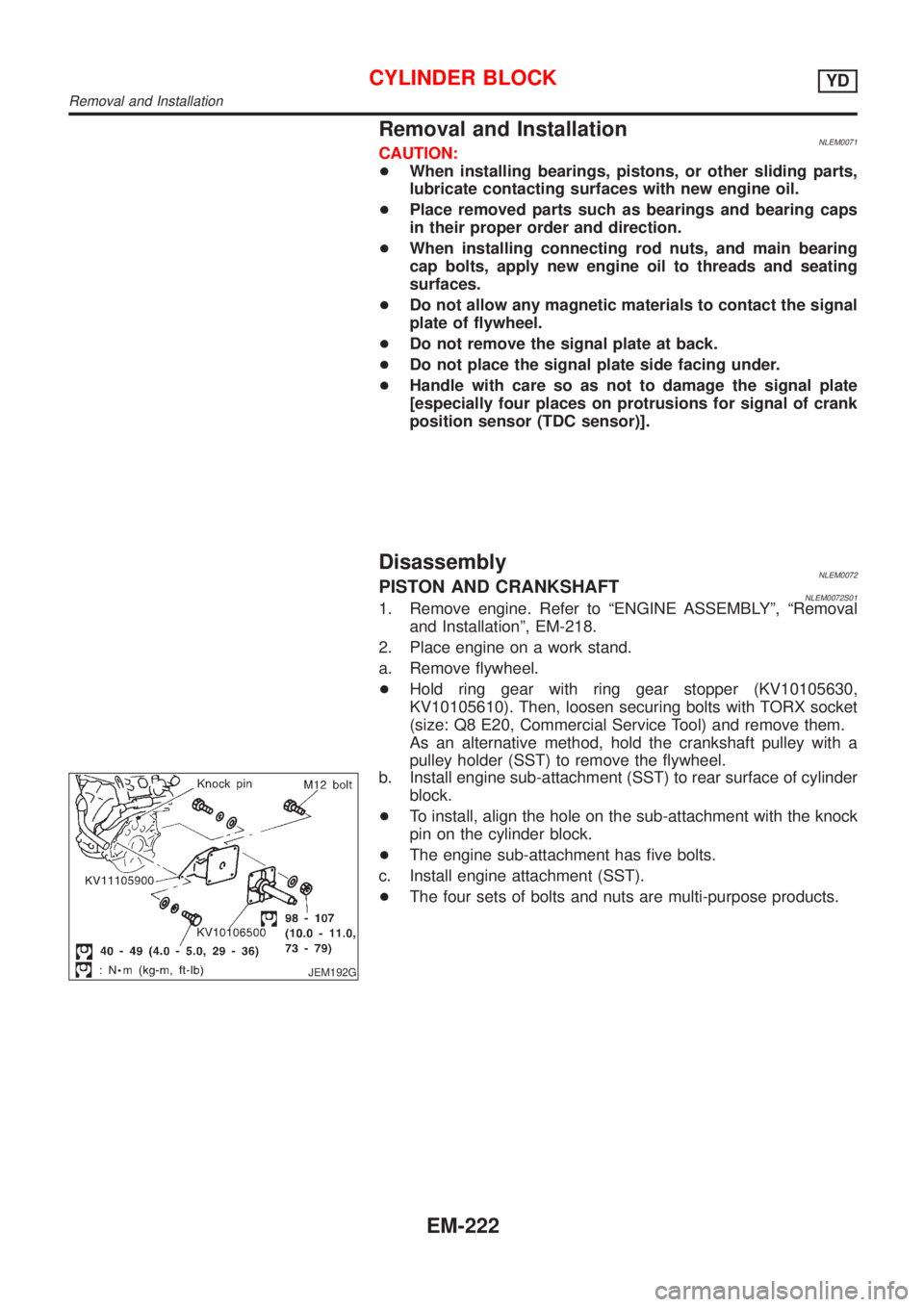
b. Install engine sub-attachment (SST) to rear surface of cylinder
block.
+To install, align the hole on the sub-attachment with the knock
pin on the cylinder block.
+The engine sub-attachment has five bolts.
c. Install engine attachment (SST).
+The four sets of bolts and nuts are multi-purpose products.
CYLINDER BLOCKYD
Removal and Installation
EM-222
Page 2493 of 3051
AssemblyNLEM0074PISTONNLEM0074S011. With using snap ring pliers, install snap rings to grooves at the
rear side of the piston.
+Install securely to fully fit into the groove.
2. Install piston to the connecting rod.
+Heat the piston with an industrial drier to 60 to 70ÉC (140 to
158ÉF) so that the piston pin can be easily inserted by finger.
Then, insert the piston pin from the front of the piston into the
piston and into the connecting rod.
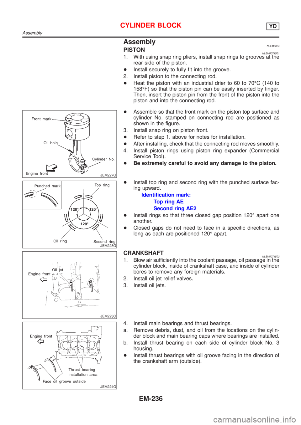
JEM227G
+Assemble so that the front mark on the piston top surface and
cylinder No. stamped on connecting rod are positioned as
shown in the figure.
3. Install snap ring on piston front.
+Refer to step 1. above for notes for installation.
+After installing, check that the connecting rod moves smoothly.
4. Install piston rings using piston ring expander (Commercial
Service Tool).
+Be extremely careful to avoid any damage to the piston.
JEM228G
+Install top ring and second ring with the punched surface fac-
ing upward.
Identification mark:
Top ring AE
Second ring AE2
+Install rings so that three closed gap position 120É apart one
another.
+Closed gaps do not need to face in a specific directions, as
long as each are positioned 120É apart.
JEM223G
CRANKSHAFTNLEM0074S021. Blow air sufficiently into the coolant passage, oil passage in the
cylinder block, inside of crankshaft case, and inside of cylinder
bores to remove any foreign materials.
2. Install oil jet relief valves.
3. Install oil jets.
JEM224G
4. Install main bearings and thrust bearings.
a. Remove debris, dust, and oil from the locations on the cylin-
der block and main bearing caps where bearings are installed.
b. Install thrust bearing on each side of cylinder block No. 3
housing.
+Install thrust bearings with oil groove facing in the direction of
the crankshaft arm (outside).
CYLINDER BLOCKYD
Assembly
EM-236
Page 2496 of 3051

JEM233G
16. Install rear oil seal retainer.
+Apply a continuous bead of specified liquid gasket (Refer to
EM-158, ªLiquid Gasket Application Procedureº.) on locations
shown in the figure.
JEM234G
17. Install pilot bushing.
+Force fit with the drift [approx. 19 mm (0.75 in) dia.].
SEM513G
18. Install fuel injection pump bracket.
+Install insulator according to the shape of the block, and secure
by placing the bracket against the insulator. (Not installed on
some models)
+Align the bracket with the dowel pins on the block to install.
+The two bolts used for dowel pins have a longer shanks than
the other two.
+Check the protruding distance of the dowel pin for fuel injec-
tion pump.
Standard: 13.0 - 15.0 mm (0.512 - 0.591 in)
19. Install parts to the engine in the reverse order of disassembly.
+Tighten bolts securing brackets of auxiliary components (A/C
compressor, alternator) to the specified torque.
: 57 - 65 N´m (5.8 - 6.7 kg-m, 42 - 48 ft-lb)
20. Remove engine from engine stand in the reverse order of
assembly.
21. Install flywheel.
+Holding ring gear with ring stopper (SST), tighten securing
bolts with TORX-socket (size: Q8 E20, Commercial Service
Tool).
+Tighten bolts uniformly in a crisscross manner.
SEM500G
REPLACEMENT OF PILOT BUSHINGNLEM0074S031. Remove pilot bushing using tool or suitable tool.
CYLINDER BLOCKYD
Assembly (Cont'd)
EM-239
Page 2513 of 3051

NFE020
4. Loosen lock nut.
5. Tighten accelerator adjusting nut until throttle drum starts to
move.
6. From that position, turn back adjusting nut 1.5 to 2 turns, and
secure lock nut.
7. Release vacuum from the throttle opener.
8. Remove vacuum pump and vacuum hose from the throttle
opener.
9. Reinstall the original vacuum hose to the throttle opener
securely.
NFE020
MODELS WITHOUT THROTTLE OPENERNLFE0003S021. Loosen lock nut, and tighten adjusting nut until throttle drum
starts to move.
2. From that position turn back adjusting nut 1.5 to 2 turns, and
secure lock nut.
ACCELERATOR CONTROL SYSTEMQG/SR
Adjusting Accelerator Wire (Cont’d)
FE-4