Page 2092 of 3051

DIAGNOSTIC PROCEDURE 6 (MODELS WITH NATS
SECURITY INDICATOR ON DASH BOARD)
=NLEL0411S10ªSECURITY INDICATOR LAMP DOES NOT LIGHT UPº
1 CHECK FUSE
Check 10A fuse [No. 12, located in the fuse block (J/B)].
Is 10A fuse OK?
Ye s©GO TO 2.
No©Replace fuse.
2 CHECK SECURITY INDICATOR LAMP
1. Install 10A fuse.
2. Perform initialization with CONSULT-II.
For initialization, refer to ªCONSULT-II Operation Manual NATSº.
3. Turn ignition switch OFF.
4. Start engine and turn ignition switch OFF.
5. Check the security indicator lamp lighting.
Security indicator lamp should be light up.
OK or NG
OK©INSPECTION END
NG©GO TO 3.
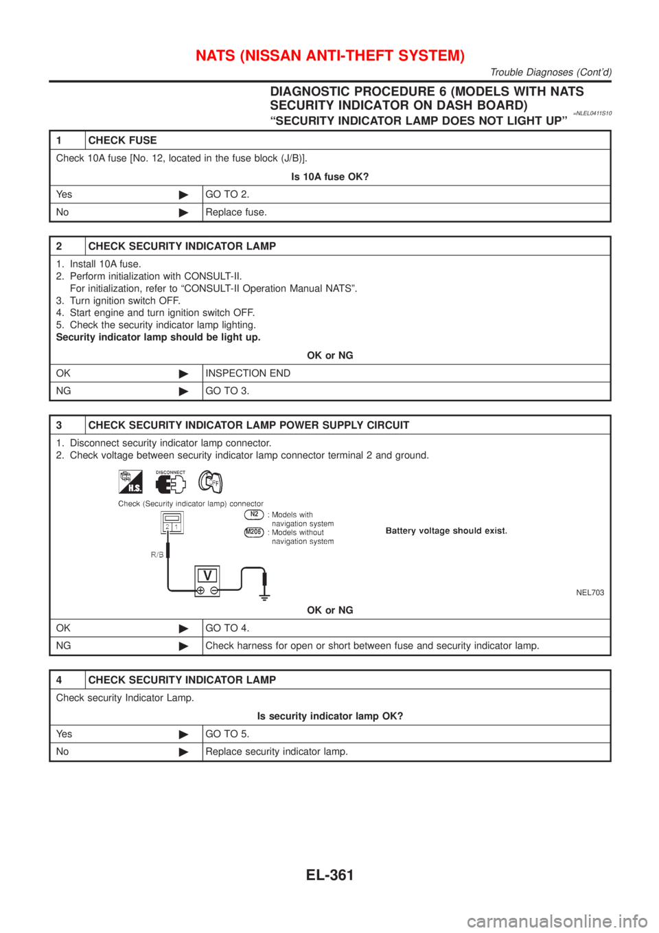
3 CHECK SECURITY INDICATOR LAMP POWER SUPPLY CIRCUIT
1. Disconnect security indicator lamp connector.
2. Check voltage between security indicator lamp connector terminal 2 and ground.
NEL703
OK or NG
OK©GO TO 4.
NG©Check harness for open or short between fuse and security indicator lamp.
4 CHECK SECURITY INDICATOR LAMP
Check security Indicator Lamp.
Is security indicator lamp OK?
Ye s©GO TO 5.
No©Replace security indicator lamp.
NATS (NISSAN ANTI-THEFT SYSTEM)
Trouble Diagnoses (Cont'd)
EL-361
Page 2093 of 3051
5 CHECK IMMU FUNCTION
1. Connect IMMU connector.
2. Disconnect security indicator lamp connector.
3. Check continuity between IMMU terminal 6 and ground.
NEL704
OK or NG
OK©Check harness for open or short between security indicator lamp and IMMU.
NG©IMMU is malfunctioning.
Replace IMMU.Ref. part No. A
Perform initialization with CONSULT-II.
For initialization, refer to ªCONSULT-II operation manual NATSº.
NATS (NISSAN ANTI-THEFT SYSTEM)
Trouble Diagnoses (Cont'd)
EL-362
Page 2094 of 3051

DIAGNOSTIC PROCEDURE 6 (MODELS WITH NATS
SECURITY INDICATOR IN COMBINATION METER)
=NLEL0411S16ªSECURITY INDICATOR LAMP DOES NOT LIGHT UPº
1 CHECK FUSE
Check 10A fuse [No. 12, located in the fuse block (J/B)].
Is 10A fuse OK?
Ye s©GO TO 2.
No©Replace fuse.
2 CHECK SECURITY INDICATOR LAMP
1. Install 10A fuse.
2. Perform initialization with CONSULT-II.
For initialization, refer to ªCONSULT-II Operation Manual NATSº.
3. Turn ignition switch OFF.
4. Start engine and turn ignition switch OFF.
5. Check the security indicator lamp lighting.
Security indicator lamp should be light up.
OK or NG
OK©INSPECTION END
NG©GO TO 3.
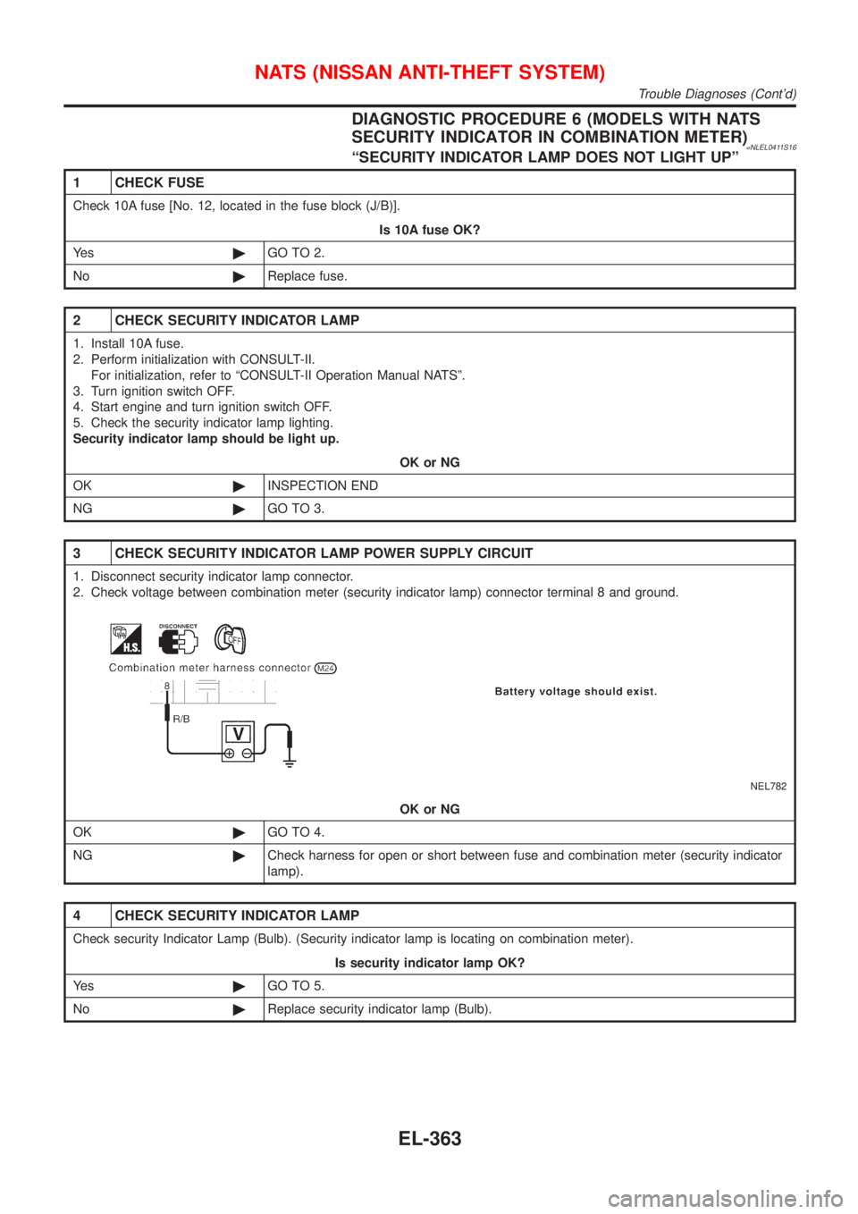
3 CHECK SECURITY INDICATOR LAMP POWER SUPPLY CIRCUIT
1. Disconnect security indicator lamp connector.
2. Check voltage between combination meter (security indicator lamp) connector terminal 8 and ground.
NEL782
OK or NG
OK©GO TO 4.
NG©Check harness for open or short between fuse and combination meter (security indicator
lamp).
4 CHECK SECURITY INDICATOR LAMP
Check security Indicator Lamp (Bulb). (Security indicator lamp is locating on combination meter).
Is security indicator lamp OK?
Ye s©GO TO 5.
No©Replace security indicator lamp (Bulb).
NATS (NISSAN ANTI-THEFT SYSTEM)
Trouble Diagnoses (Cont'd)
EL-363
Page 2095 of 3051
5 CHECK IMMU FUNCTION
1. Connect IMMU connector.
2. Disconnect combination meter (security indicator lamp) connector.
3. Check continuity between IMMU terminal 6 and ground.
NEL704
OK or NG
OK©Check harness for open or short between combination meter (security indicator lamp)
and IMMU.
NG©IMMU is malfunctioning.
Replace IMMU.Ref. part No. A
Perform initialization with CONSULT-II.
For initialization, refer to ªCONSULT-II operation manual NATSº.
NATS (NISSAN ANTI-THEFT SYSTEM)
Trouble Diagnoses (Cont'd)
EL-364
Page 2099 of 3051
DIAGNOSTIC PROCEDURE 8=NLEL0411S14
1 CHECK HARNESS CONNECTOR CONNECTION
Perform initialization with CONSULT-II.
Check harness connector connection between M31 and M102.
Then initialize NATS. For the initialization operation, refer to ªCONSULT-II operation NATSº.
Does the security indicator blink just after initialization?
Ye s©System is OK. (The malfunction is caused by improper connector connection.)
No©GO TO 2.
2 CHECK GROUND CIRCUIT FOR DONGLE UNIT
Check continuity between dongle unit terminal 1 and ground.
NEL777
YesorNo
Ye s©GO TO 3.
No©Repair harness.
3 CHECK INTERFACE CIRCUIT
NEL778
YesorNo
Ye s©Dongle unit is malfunctioning.
1. Replace dongle unit.
2. Perform initialization with CONSULT-II. For the initialization procedure, refer to ªCON-
SULT-II Operation Manual NATSº.
No©Repair harness.
NATS (NISSAN ANTI-THEFT SYSTEM)
Trouble Diagnoses (Cont'd)
EL-368
Page 2156 of 3051

SEF094Y
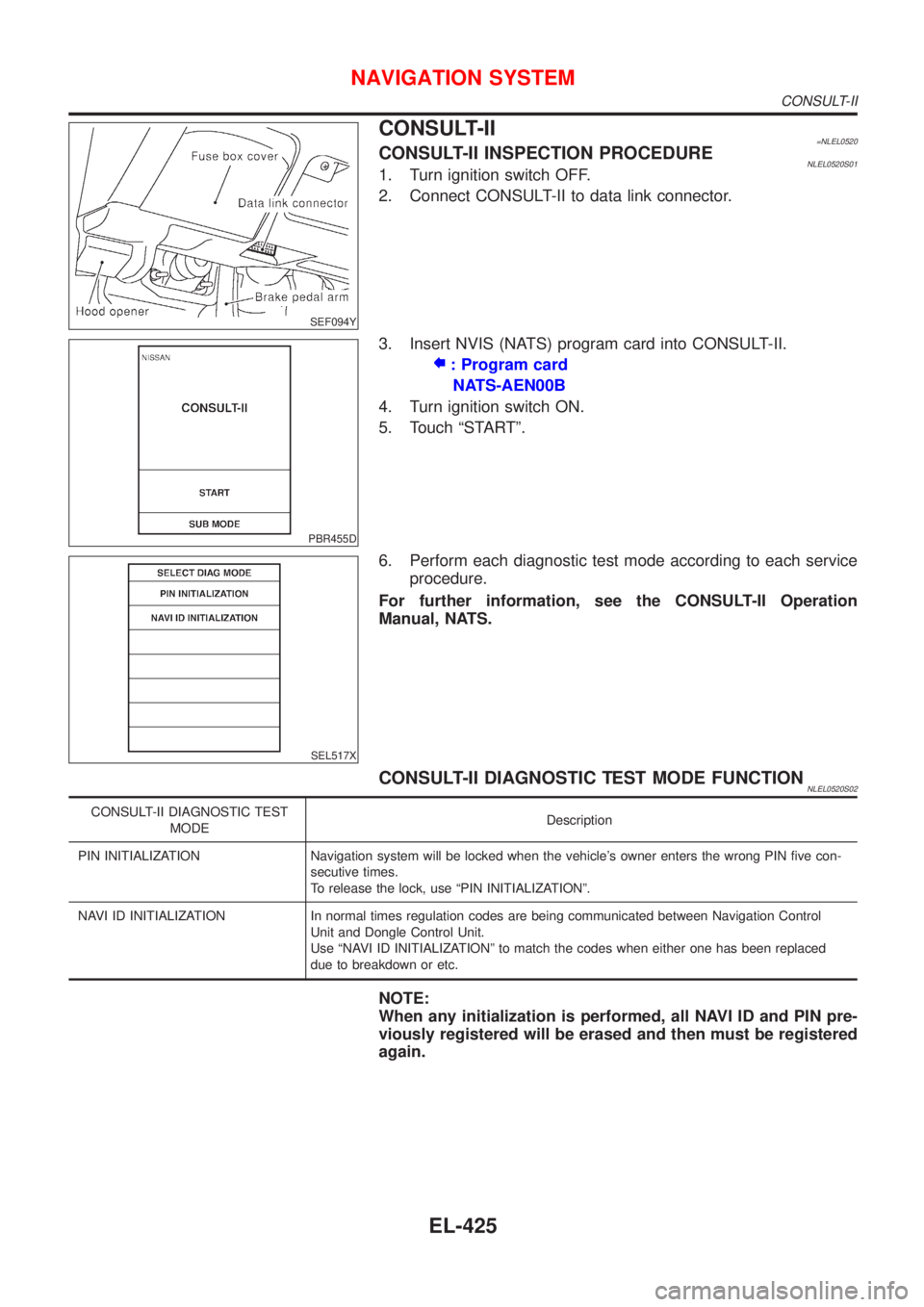
CONSULT-II=NLEL0520CONSULT-II INSPECTION PROCEDURENLEL0520S011. Turn ignition switch OFF.
2. Connect CONSULT-II to data link connector.
PBR455D
3. Insert NVIS (NATS) program card into CONSULT-II.
: Program card
NATS-AEN00B
4. Turn ignition switch ON.
5. Touch ªSTARTº.
SEL517X
6. Perform each diagnostic test mode according to each service
procedure.
For further information, see the CONSULT-II Operation
Manual, NATS.
CONSULT-II DIAGNOSTIC TEST MODE FUNCTIONNLEL0520S02
CONSULT-II DIAGNOSTIC TEST
MODEDescription
PIN INITIALIZATION Navigation system will be locked when the vehicle's owner enters the wrong PIN five con-
secutive times.
To release the lock, use ªPIN INITIALIZATIONº.
NAVI ID INITIALIZATION In normal times regulation codes are being communicated between Navigation Control
Unit and Dongle Control Unit.
Use ªNAVI ID INITIALIZATIONº to match the codes when either one has been replaced
due to breakdown or etc.
NOTE:
When any initialization is performed, all NAVI ID and PIN pre-
viously registered will be erased and then must be registered
again.
NAVIGATION SYSTEM
CONSULT-II
EL-425
Page 2318 of 3051
SEM160B
+Align piston rings so that end gaps are positioned as
shown.
SEM934F
SEM366E
SEM420C
CRANKSHAFTNLEM0027S021. Install signal plate to crankshaft.
2. Set main bearings in their proper positions on cylinder block
and main bearing cap.
+Confirm that correct main bearings are selected by using
Method A or Method B. Refer to EM-57.
+Apply new engine oil to bearing surfaces.
SEM933F
3. Install crankshaft and main bearing caps and tighten bolts to
the specified torque.
+Apply new engine oil to the bolt thread and seat surface.
+Prior to tightening bearing cap bolts, shift crankshaft back
and forth to properly seat the bearing caps.
+Tighten bearing cap bolts gradually in two or three stages.
Start with center bearing and move outward as shown in
figure.
+After securing bearing cap bolts, make sure crankshaft
turns smoothly by hand.
CYLINDER BLOCKQG
Assembly (Cont'd)
EM-61
Page 2400 of 3051

SEM160B
+Align piston rings so that end gaps are positioned as
shown.
SEM685D
CRANKSHAFTNLEM0142S021. Set main bearings in their proper positions on cylinder block
and main bearing cap.
+Confirm that correct main bearings are selected by using
Method A or Method B. Refer to EM-138.
+Apply new engine oil to bearing surfaces.
SEM069G
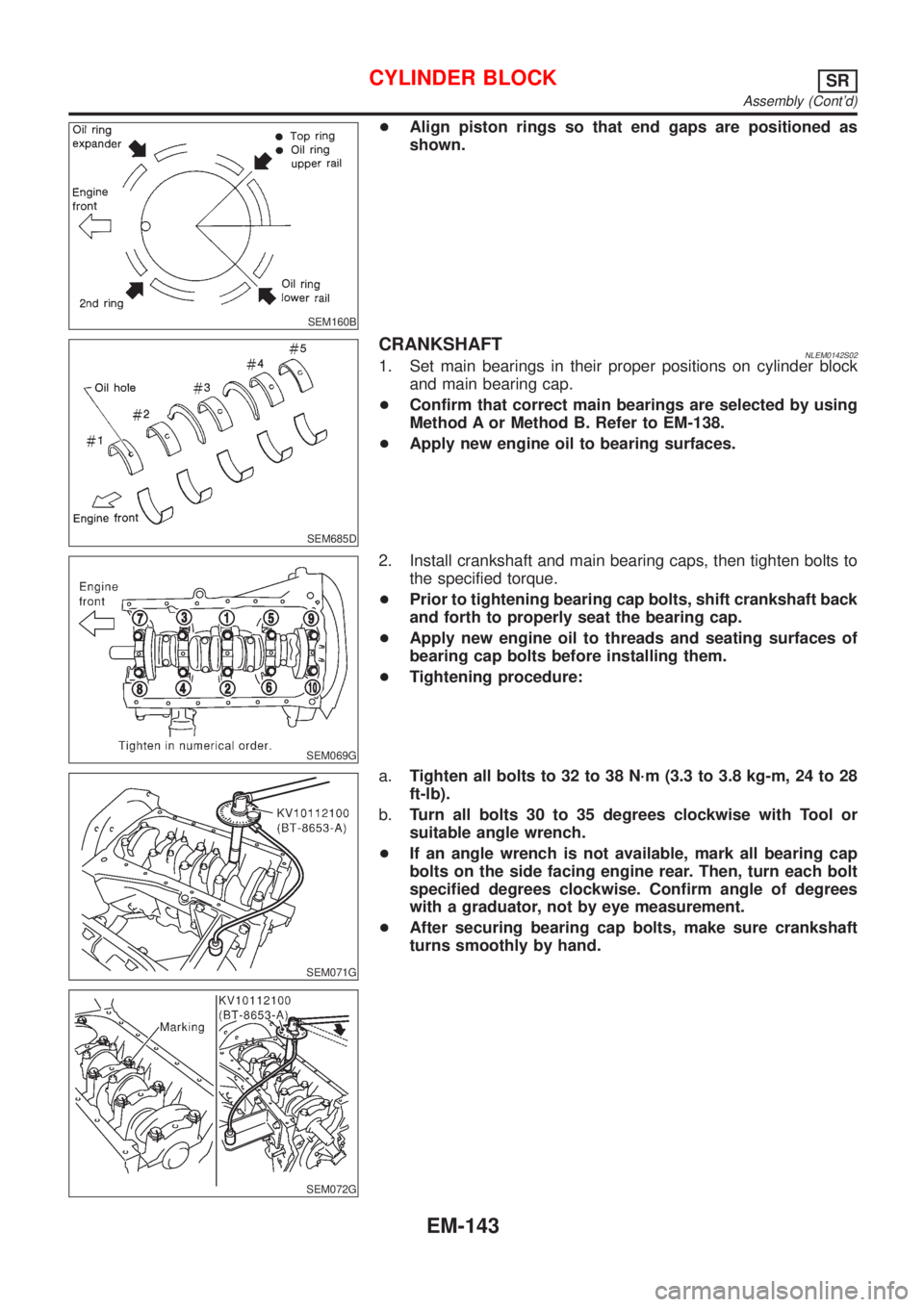
2. Install crankshaft and main bearing caps, then tighten bolts to
the specified torque.
+Prior to tightening bearing cap bolts, shift crankshaft back
and forth to properly seat the bearing cap.
+Apply new engine oil to threads and seating surfaces of
bearing cap bolts before installing them.
+Tightening procedure:
SEM071G
SEM072G
a.Tighten all bolts to 32 to 38 N´m (3.3 to 3.8 kg-m, 24 to 28
ft-lb).
b.Turn all bolts 30 to 35 degrees clockwise with Tool or
suitable angle wrench.
+If an angle wrench is not available, mark all bearing cap
bolts on the side facing engine rear. Then, turn each bolt
specified degrees clockwise. Confirm angle of degrees
with a graduator, not by eye measurement.
+After securing bearing cap bolts, make sure crankshaft
turns smoothly by hand.
CYLINDER BLOCKSR
Assembly (Cont'd)
EM-143