Page 350 of 3051
NBT100
2. Remove inside handle escutcheon A.
3. Remove screw securing inside handle.
4. Detach bell crank at lock knob joining area.
5. Detach inside handle rod on the door lock assembly side.
6. Slide inside handle backward and remove inside handle.
7. Remove rod from inside handle.
NBT101
8. Detach key lock rod and outside handle rod at joining area (on
the outside handle side).
9. Disconnect door lock actuator connector.
10. Remove screws securing door lock assembly, then remove
door lock assembly.
11. Remove bolts securing outside handle, then remove outside
handle assembly.
DOOR
Front Door Lock (Cont'd)
BT-19
Page 352 of 3051
SBT983
REMOVAL=NLBT0011S02+For removal of rear door finisher, refer to ªDOOR TRIMº,
BT-32.
+Remove sealing screen.
+Set the door glass in the full-close position.
1. Remove inside handle escutcheon A.
2. Remove screw securing inside handle.
3. Detach inside handle rod on the door lock assembly side.
NBT103
4. Detach lock knob rod (on the door lock assembly side).
5. Using a flat-bladed screwdriver, expand rod holder. Remove
rod from rod holder.
6. Slide inside handle backward and remove inside handle.
7. Remove rod from inside handle.
8. Disconnect door lock actuator connector.
9. Remove screws securing door lock assembly, then remove
door lock assembly.
10. Remove bolts securing outside handle, then remove outside
handle.
DOOR
Rear Door Lock (Cont'd)
BT-21
Page 363 of 3051
Removal and InstallationNLBT0014Front door finisher
1. Open the window.
2. Remove inside handle escutcheon.
3. Remove screw securing pull handle.
4. Remove screw securing door finisher.
5. Remove clips securing front door finisher.
6. Lift out front door finisher.
7. Remove power window switch by pushing from backside, then disconnect the connectors.
Rear door finisher
8. Remove inside handle escutcheon.
9. Remove screw securing power window switch finisher, then disconnect the connector. (Power window
model)
10. Remove screw securing pull handle. (Manual window model)
11. Remove window regulator handle. (Manual window model)
12. Remove clips securing rear door finisher.
13. Lift out rear door finisher.
DOOR TRIM
Removal and Installation
BT-32
Page 366 of 3051
Removal and InstallationNLBT00151. Remove rear seat.
2. Remove shoulder anchor bolts. Refer to RS-5, ªFront Seat Beltº for details.
3. Remove front pillar garnishes, center pillar upper garnishes, center pillar lower garnishes and rear pillar
garnishes. Refer to ªSIDE AND FLOOR TRIMº for details, BT-28.
4. Push back the front seat back.
5. Remove sunroof switch, then disconnect connectors. (Model with sunroof)
6. Remove front personal light then disconnect connector (Model without sunroof)
7. Remove sunroof welt. (Model with sunroof)
8. Remove interior lamp assembly, then disconnect connectors.
9. Remove sun visors.
10. Remove assist grips.
11. Remove clips securing headlining, then remove headlining from vehicle through back door side.
NBT113
ROOF TRIM
Removal and Installation
BT-35
Page 385 of 3051
NBT145
Record the number of shims placed between glass lid assem-
bly and link and wire assembly. Remove securing screws and glass
lid assembly.
NBT146
Remove shade stoppers (2 points) from rear end of sunroof
frame assembly. Remove sun shade from rear end of sunroof
frame assembly.
NBT147
Remove screws from left and right sides of each wind deflector
holder. Then remove left and right sides of wind deflector holder.
Remove screws from front end of sunroof unit. Then remove wind
deflector from frame assembly.
(If wind deflector is equipped).
NBT148
CAUTION:
+Before removing sunroof motor, make sure that sunroof is
fully closed.
+After removing sunroof motor, never attempt to rotate
sunroof motor as a single unit.
SUNROOF
Removal (Cont'd)
BT-54
Page 390 of 3051

SBF034BA
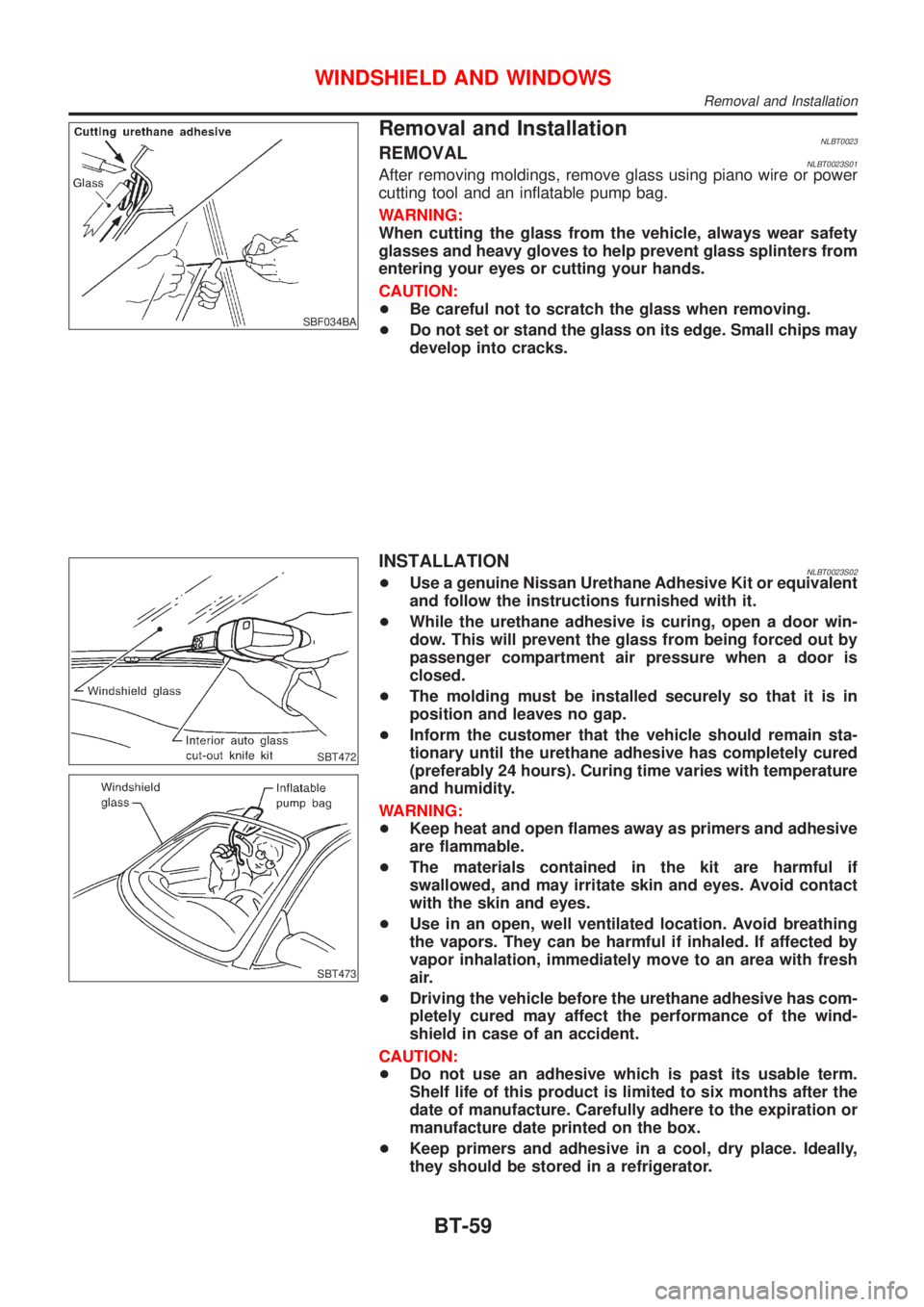
Removal and InstallationNLBT0023REMOVALNLBT0023S01After removing moldings, remove glass using piano wire or power
cutting tool and an inflatable pump bag.
WARNING:
When cutting the glass from the vehicle, always wear safety
glasses and heavy gloves to help prevent glass splinters from
entering your eyes or cutting your hands.
CAUTION:
+Be careful not to scratch the glass when removing.
+Do not set or stand the glass on its edge. Small chips may
develop into cracks.
SBT472
SBT473
INSTALLATIONNLBT0023S02+Use a genuine Nissan Urethane Adhesive Kit or equivalent
and follow the instructions furnished with it.
+While the urethane adhesive is curing, open a door win-
dow. This will prevent the glass from being forced out by
passenger compartment air pressure when a door is
closed.
+The molding must be installed securely so that it is in
position and leaves no gap.
+Inform the customer that the vehicle should remain sta-
tionary until the urethane adhesive has completely cured
(preferably 24 hours). Curing time varies with temperature
and humidity.
WARNING:
+Keep heat and open flames away as primers and adhesive
are flammable.
+The materials contained in the kit are harmful if
swallowed, and may irritate skin and eyes. Avoid contact
with the skin and eyes.
+Use in an open, well ventilated location. Avoid breathing
the vapors. They can be harmful if inhaled. If affected by
vapor inhalation, immediately move to an area with fresh
air.
+Driving the vehicle before the urethane adhesive has com-
pletely cured may affect the performance of the wind-
shield in case of an accident.
CAUTION:
+Do not use an adhesive which is past its usable term.
Shelf life of this product is limited to six months after the
date of manufacture. Carefully adhere to the expiration or
manufacture date printed on the box.
+Keep primers and adhesive in a cool, dry place. Ideally,
they should be stored in a refrigerator.
WINDSHIELD AND WINDOWS
Removal and Installation
BT-59
Page 394 of 3051
Removal and InstallationNLBT0024CAUTION:
Be careful not to scratch door rearview mirror body.
HFor Wiring Diagram, refer to EL-241, ªDOOR MIRRORº for details.
1. Remove front corner of door inner cover.
2. Disconnect door mirror harness connector.
3. Remove bolts securing door mirror assembly.
4. Remove the mirror glass. Do not insert flat-bladed screwdriver too far.
NBT131
DOOR MIRROR
Removal and Installation
BT-63
Page 417 of 3051

SCL729
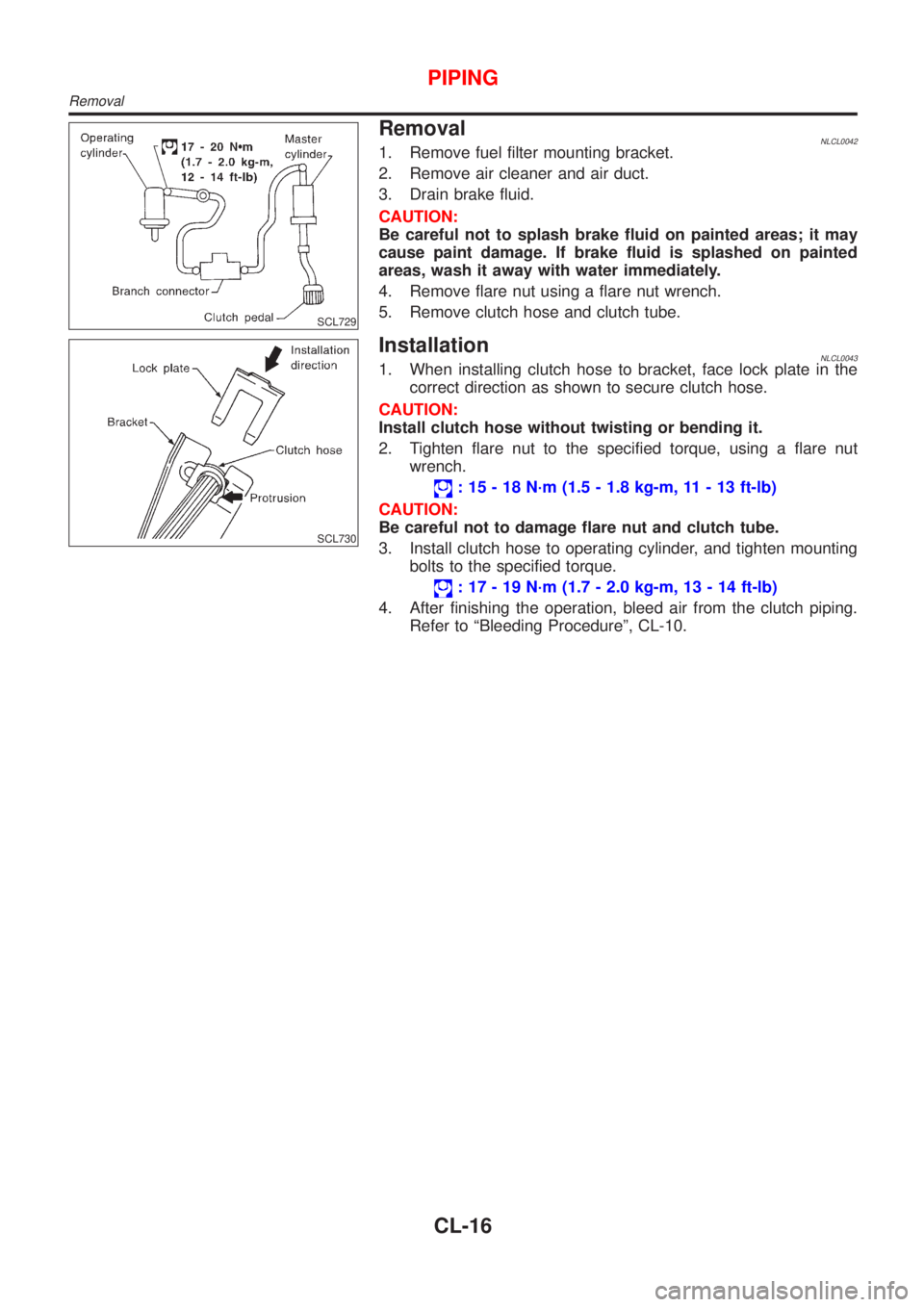
RemovalNLCL00421. Remove fuel filter mounting bracket.
2. Remove air cleaner and air duct.
3. Drain brake fluid.
CAUTION:
Be careful not to splash brake fluid on painted areas; it may
cause paint damage. If brake fluid is splashed on painted
areas, wash it away with water immediately.
4. Remove flare nut using a flare nut wrench.
5. Remove clutch hose and clutch tube.
SCL730
InstallationNLCL00431. When installing clutch hose to bracket, face lock plate in the
correct direction as shown to secure clutch hose.
CAUTION:
Install clutch hose without twisting or bending it.
2. Tighten flare nut to the specified torque, using a flare nut
wrench.
: 15 - 18 N´m (1.5 - 1.8 kg-m, 11 - 13 ft-lb)
CAUTION:
Be careful not to damage flare nut and clutch tube.
3. Install clutch hose to operating cylinder, and tighten mounting
bolts to the specified torque.
: 17 - 19 N´m (1.7 - 2.0 kg-m, 13 - 14 ft-lb)
4. After finishing the operation, bleed air from the clutch piping.
Refer to ªBleeding Procedureº, CL-10.
PIPING
Removal
CL-16