Page 188 of 2898
Diagnostic ProcedureNJAT0266
1 CHECK PNP SWITCH CIRCUIT (With CONSULT-II)
With CONSULT-II
1. Turn ignition switch to ªONº position.
(Do not start engine.)
2. Select ªECU INPUT SIGNALSº in ªDATA MONITORº mode for ªA/Tº with CONSULT-II.
SAT014K
3. Read out ªP/Nº, ªRº, ªDº, ª2º and ª1º position switches moving selector lever to each position.
Check the signal of the selector lever position is indicated properly.
SAT701J
OK or NG
OK©GO TO 3.
NG©Check the following items:
+PNP switch
Refer to ªComponent Inspectionº, AT-188.
+Harness for short or open between ignition switch and PNP switch (Main harness)
+Harness for short or open between PNP switch and TCM (Main harness)
+Ignition switch and fuse
Refer to EL-10, ªPOWER SUPPLY ROUTINGº.
+Diode (P, N positions)
DTC P0705 PARK/NEUTRAL POSITION (PNP) SWITCHEURO-OBD
Diagnostic Procedure
AT-186
Page 194 of 2898
Diagnostic ProcedureNJAT0270
1 INSPECTION START
Do you have CONSULT-II?
YesorNo
Ye s©GO TO 2.
No©GO TO 3.
2 CHECK INPUT SIGNAL OF A/T FLUID TEMPERATURE SENSOR (With CONSULT-II)
With CONSULT-II
1. Start engine.
2. Select ªECU INPUT SIGNALSº in ªDATA MONITORº mode for ªA/Tº with CONSULT-II.
SAT014K
3. Read out the value of ªFLUID TEMP SEº.
Voltage:
Cold [20ÉC (68ÉF)]®Hot [80ÉC (176ÉF)]:
Approximately 1.5V®0.5V
SAT614J
OK or NG
OK©GO TO 4.
NG©GO TO 5.
DTC P0710 A/T FLUID TEMPERATURE SENSOR CIRCUITEURO-OBD
Diagnostic Procedure
AT-192
Page 198 of 2898

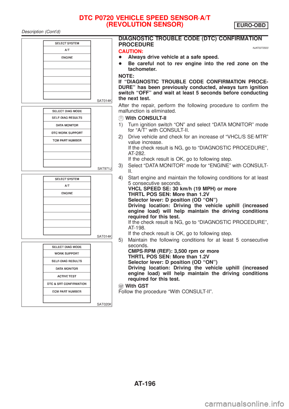
SAT014K
SAT971J
SAT014K
SAT020K
DIAGNOSTIC TROUBLE CODE (DTC) CONFIRMATION
PROCEDURE
NJAT0272S03CAUTION:
+Always drive vehicle at a safe speed.
+Be careful not to rev engine into the red zone on the
tachometer.
NOTE:
If ªDIAGNOSTIC TROUBLE CODE CONFIRMATION PROCE-
DUREº has been previously conducted, always turn ignition
switch ªOFFº and wait at least 5 seconds before conducting
the next test.
After the repair, perform the following procedure to confirm the
malfunction is eliminated.
With CONSULT-II
1) Turn ignition switch ªONº and select ªDATA MONITORº mode
for ªA/Tº with CONSULT-II.
2) Drive vehicle and check for an increase of ªVHCL/S SE´MTRº
value increase.
If the check result is NG, go to ªDIAGNOSTIC PROCEDUREº,
AT-282.
If the check result is OK, go to following step.
3) Select ªDATA MONITORº mode for ªENGINEº with CONSULT-
II.
4) Start engine and maintain the following conditions for at least
5 consecutive seconds.
VHCL SPEED SE: 30 km/h (19 MPH) or more
THRTL POS SEN: More than 1.2V
Selector lever: D position (OD ªONº)
Driving location: Driving the vehicle uphill (increased
engine load) will help maintain the driving conditions
required for this test.
If the check result is NG, go to ªDIAGNOSTIC PROCEDUREº,
AT-198.
If the check result is OK, go to following step.
5) Maintain the following conditions for at least 5 consecutive
seconds.
CMPS´RPM (REF): 3,500 rpm or more
THRTL POS SEN: More than 1.2V
Selector lever: D position (OD ªONº)
Driving location: Driving the vehicle uphill (increased
engine load) will help maintain the driving conditions
required for this test.
With GST
Follow the procedure ªWith CONSULT-IIº.
DTC P0720 VEHICLE SPEED SENSOR´A/T
(REVOLUTION SENSOR)
EURO-OBD
Description (Cont'd)
AT-196
Page 200 of 2898
Diagnostic ProcedureNJAT0274
1 CHECK INPUT SIGNAL (With CONSULT-II)
With CONSULT-II
1. Start engine.
2. Select ªECU INPUT SIGNALSº in ªDATA MONITORº mode for ªA/Tº with CONSULT-II.
SAT014K
3. Read out the value of ªVHCL/S SE´A/Tº while driving.
Check the value changes according to driving speed.
SAT614J
OK or NG
OK©GO TO 3.
NG©GO TO 2.
2 CHECK REVOLUTION SENSOR (With CONSULT-II)
With CONSULT-II
1. Start engine.
MTBL0455
+Harness for short or open between TCM, ECM and revolution sensor (Main harness)
OK or NG
OK©GO TO 3.
NG©Repair or replace damaged parts.
DTC P0720 VEHICLE SPEED SENSOR´A/T
(REVOLUTION SENSOR)
EURO-OBD
Diagnostic Procedure
AT-198
Page 202 of 2898

DescriptionNJAT0276The engine speed signal is sent from the ECM to the TCM.
TCM TERMINALS AND REFERENCE VALUENJAT0276S01Remarks: Specification data are reference values.
Terminal
No.Wire color Item ConditionJudgement stan-
dard
39 L/OREngine speed
signal
Refer to EC-166, ªECM INSPECTION
TABLEº.Ð
ON BOARD DIAGNOSIS LOGICNJAT0276S02
Diagnostic trouble code Malfunction is detected when ... Check item (Possible cause)
: ENGINE SPEED SIG
TCM does not receive the proper voltage
signal from ECM.+Harness or connectors
(The sensor circuit is open or shorted.)
: P0725
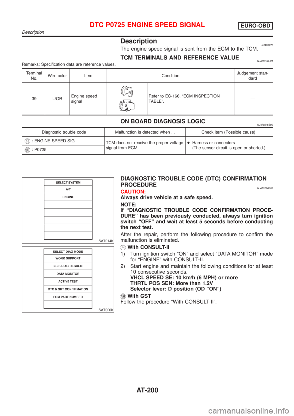
SAT014K
SAT020K
DIAGNOSTIC TROUBLE CODE (DTC) CONFIRMATION
PROCEDURE
NJAT0276S03CAUTION:
Always drive vehicle at a safe speed.
NOTE:
If ªDIAGNOSTIC TROUBLE CODE CONFIRMATION PROCE-
DUREº has been previously conducted, always turn ignition
switch ªOFFº and wait at least 5 seconds before conducting
the next test.
After the repair, perform the following procedure to confirm the
malfunction is eliminated.
With CONSULT-II
1) Turn ignition switch ªONº and select ªDATA MONITORº mode
for ªENGINEº with CONSULT-II.
2) Start engine and maintain the following conditions for at least
10 consecutive seconds.
VHCL SPEED SE: 10 km/h (6 MPH) or more
THRTL POS SEN: More than 1.2V
Selector lever: D position (OD ªONº)
With GST
Follow the procedure ªWith CONSULT-IIº.
DTC P0725 ENGINE SPEED SIGNALEURO-OBD
Description
AT-200
Page 204 of 2898
Diagnostic ProcedureNJAT0278
1 CHECK DTC WITH ECM
Perform diagnostic test mode II (self- diagnostic results) for engine control. Check ignition signal circuit condition.
OK or NG
OK (With CONSULT-II)©GO TO 2.
OK (Without CONSULT-
II)©GO TO 3.
NG©Check ignition signal circuit for engine control. Refer to EC-547, ªIGNITION SIGNALº.
2 CHECK INPUT SIGNAL (With CONSULT-II)
With CONSULT-II
1. Start engine.
2. Select ªECU INPUT SIGNALSº in ªDATA MONITORº mode for ªA/Tº with CONSULT-II.
SAT014K
3. Read out the value of ªENGINE SPEEDº.
Check engine speed changes according to throttle position.
SAT645J
OK or NG
OK©GO TO 4.
NG©Check the following items:
+Harness for short or open between TCM and ECM
+Resistor and ignition coil
Refer to EC-547, ªIGNITION SIGNALº.
DTC P0725 ENGINE SPEED SIGNALEURO-OBD
Diagnostic Procedure
AT-202
Page 261 of 2898

ON BOARD DIAGNOSIS LOGICNJAT0311S03
Diagnostic trouble code Malfunction is detected when ... Check items (Possible cause)
: TP SEN/CIRC A/T
TCM receives an excessively low or high
voltage from the sensor.+Harness or connectors
(The sensor circuit is open or shorted.)
+Throttle position sensor
+Throttle position switch
: P1705
SAT014K
SAT971J
SAT014K
SAT020K
DIAGNOSTIC TROUBLE CODE (DTC) CONFIRMATION
PROCEDURE
NJAT0311S04CAUTION:
Always drive vehicle at a safe speed.
NOTE:
If ªDIAGNOSTIC TROUBLE CODE CONFIRMATION PROCE-
DUREº has been previously conducted, always turn ignition
switch ªOFFº and wait at least 5 seconds before conducting
the next test.
After the repair, perform the following procedure to confirm the
malfunction is eliminated.
With CONSULT-II
1) Apply vacuum to the throttle opener, then check the following.
Refer to steps from 1 to 5 of ªPreparationº, ªTCM SELF-DIAG-
NOSTIC PROCEDURE (No Tools)º, AT-63.
2) Turn ignition switch ªONº and select ªDATA MONITORº mode
for ªA/Tº with CONSULT-II.
3) Check the following.
Accelerator pedal
conditionTHRTL POS SEN CLOSED THL/SW W/O THRL/P´SW
Fully released Less than 4.7V ON OFF
Partially
depressed0.1 - 4.6V OFF OFF
Fully depressed 1.9 - 4.6V OFF ON
If the check result is NG, go to ªDIAGNOSTIC PROCEDUREº,
AT-263.
If the check result is OK, go to following step.
4) Turn ignition switch ªONº and select ªDATA MONITORº mode
for ªENGINEº with CONSULT-II.
5) Start engine and maintain the following conditions for at least
3 consecutive seconds. Then release accelerator pedal com-
pletely.
VHCL SPEED SE: 10 km/h (6 MPH) or more
THRTL POS SEN: Approximately 3V or less
Selector lever: D position (OD ªONº)
If the check result is NG, go to ªDIAGNOSTIC PROCEDUREº,
AT-263.
If the check result is OK, go to following step.
6) Maintain the following conditions for at least 3 consecutive
seconds. Then release accelerator pedal completely.
VHCL SPEED SE: 10 km/h (6 MPH) or more
Accelerator pedal: Wide open throttle
Selector lever: D position (OD ªONº)
DTC P1705 THROTTLE POSITION SENSOREURO-OBD
Description (Cont'd)
AT-259
Page 265 of 2898

Diagnostic ProcedureNJAT0313
1 CHECK DTC WITH ECM
Perform diagnostic test mode II (self-diagnostic results) for engine control.
Refer to EC-74, ªMalfunction Indicator Lamp (MIL)º.
OK or NG
OK (With CONSULT-II)©GO TO 2.
OK (Without CONSULT-
II)©GO TO 3.
NG©Check throttle position sensor circuit for engine control. Refer to EC-207, ªDTC P0120
THROTTLE POSITION SENSORº.
2 CHECK INPUT SIGNAL (WITH CONSULT-II)
With CONSULT-II
1. Apply vacuum to the throttle opener then check the following. Refer from step 1 to 5 of ªPreparationº, ªTCM SELF-DI-
AGNOSTIC PROCEDURE (No Tools)º, AT-63.
2. Turn ignition switch to ªONº position.
(Do not start engine.)
3. Select ªECU INPUT SIGNALSº in ªDATA MONITORº mode for ªA/Tº with CONSULT-II.
SAT014K
4. Read out the value of ªTHRTL POS SENº.
Voltage:
Fully-closed throttle:
Approximately 0.5V
Fully-open throttle:
Approximately 4V
SAT614J
OK or NG
OK©GO TO 4.
NG©Check harness for short or open between ECM and TCM regarding throttle position sen-
sor circuit. (Main harness)
DTC P1705 THROTTLE POSITION SENSOREURO-OBD
Diagnostic Procedure
AT-263