Page 95 of 2898
SAT580J
5. Touch ªA/Tº.
SAT971J
6. Touch ªDATA MONITORº.
SAT972J
7. Touch ªMAIN SIGNALSº or ªECU INPUT SIGNALSº.
8. Select ªNumerical Displayº, ªBarchart Displayº or ªLine Graph
Displayº.
SAT973J
9. Touch ªSETTINGº to recording condition (ªAUTO TRIGº or
ªMANU TRIGº) and touch ªBACKº.
10. Touch ªStartº.
SAT985J
11. When performing cruise test, touch ªRECORDº.
TROUBLE DIAGNOSIS Ð BASIC INSPECTION
Road Test (Cont'd)
AT-93
Page 131 of 2898
Diagnostic ProcedureNJAT0039
1 CHECK INPUT SIGNAL (With CONSULT-II)
With CONSULT-II
1. Start engine.
2. Select ªECU INPUT SIGNALSº in ªDATA MONITORº mode for ªA/Tº with CONSULT-II.
SAT580J
3. Read out the value of ªVHCL/S SE´A/Tº while driving.
Check the value changes according to driving speed.
SAT614J
OK or NG
OK©GO TO 3.
NG©GO TO 2.
2 CHECK REVOLUTION SENSOR (With CONSULT-II)
With CONSULT-II
1. Start engine.
MTBL0452
+Harness for short or open between TCM, ECM and revolution sensor (Main harness)
OK or NG
OK©GO TO 3.
NG©Repair or replace damaged parts.
VEHICLE SPEED SENSOR´A/T
(REVOLUTION SENSOR)
EXCEPT FOR EURO-OBD
Diagnostic Procedure
AT-129
Page 135 of 2898

Diagnostic ProcedureNJAT0080
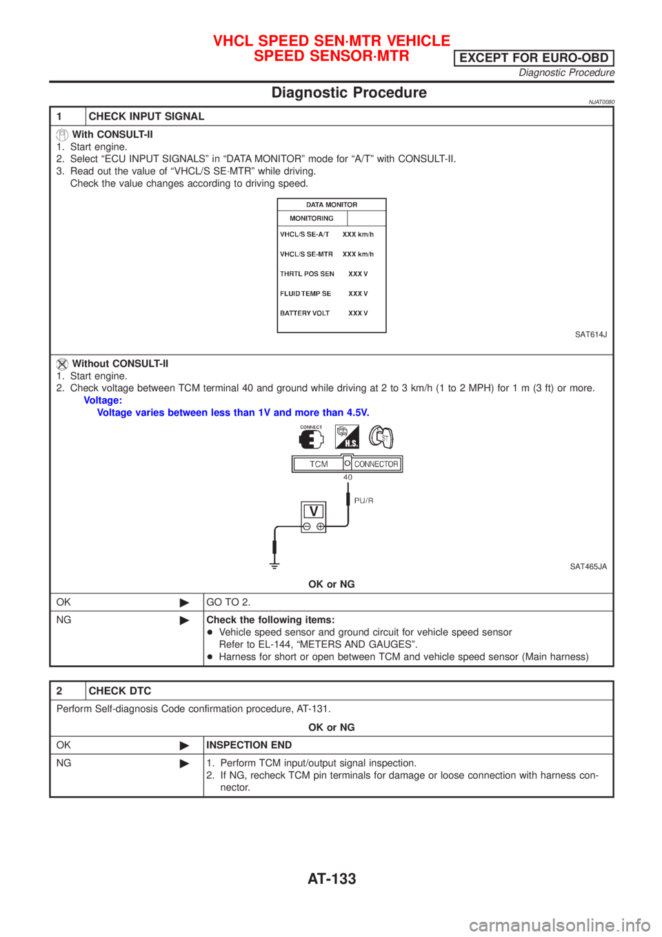
1 CHECK INPUT SIGNAL
With CONSULT-II
1. Start engine.
2. Select ªECU INPUT SIGNALSº in ªDATA MONITORº mode for ªA/Tº with CONSULT-II.
3. Read out the value of ªVHCL/S SE´MTRº while driving.
Check the value changes according to driving speed.
SAT614J
Without CONSULT-II
1. Start engine.
2. Check voltage between TCM terminal 40 and ground while driving at 2 to 3 km/h (1 to 2 MPH) for1m(3ft)ormore.
Voltage:
Voltage varies between less than 1V and more than 4.5V.
SAT465JA
OK or NG
OK©GO TO 2.
NG©Check the following items:
+Vehicle speed sensor and ground circuit for vehicle speed sensor
Refer to EL-144, ªMETERS AND GAUGESº.
+Harness for short or open between TCM and vehicle speed sensor (Main harness)
2 CHECK DTC
Perform Self-diagnosis Code confirmation procedure, AT-131.
OK or NG
OK©INSPECTION END
NG©1. Perform TCM input/output signal inspection.
2. If NG, recheck TCM pin terminals for damage or loose connection with harness con-
nector.
VHCL SPEED SEN´MTR VEHICLE
SPEED SENSOR´MTR
EXCEPT FOR EURO-OBD
Diagnostic Procedure
AT-133
Page 139 of 2898

Diagnostic ProcedureNJAT0071
1 CHECK DTC WITH ECM
Perform diagnostic test mode II (self-diagnostic results) for engine control.
Refer to EC-74, ªMalfunction Indicator Lamp (MIL)º.
OK or NG
OK (With CONSULT-II)©GO TO 2.
OK (Without CONSULT-
II)©GO TO 3.
NG©Check throttle position sensor circuit for engine control. Refer to EC-207, ªDTC P0120
THROTTLE POSITION SENSORº.
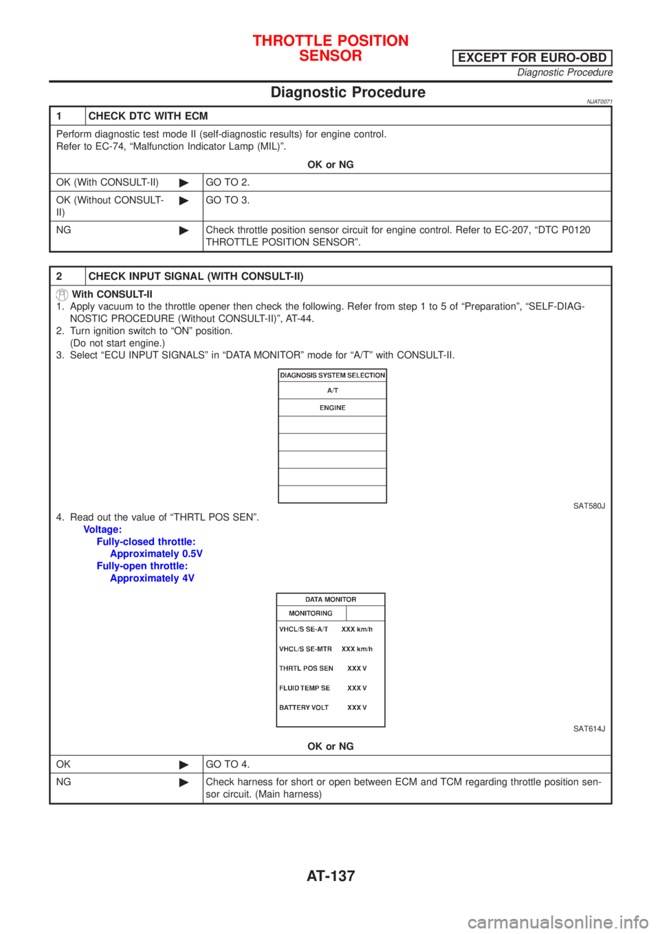
2 CHECK INPUT SIGNAL (WITH CONSULT-II)
With CONSULT-II
1. Apply vacuum to the throttle opener then check the following. Refer from step 1 to 5 of ªPreparationº, ªSELF-DIAG-
NOSTIC PROCEDURE (Without CONSULT-II)º, AT-44.
2. Turn ignition switch to ªONº position.
(Do not start engine.)
3. Select ªECU INPUT SIGNALSº in ªDATA MONITORº mode for ªA/Tº with CONSULT-II.
SAT580J
4. Read out the value of ªTHRTL POS SENº.
Voltage:
Fully-closed throttle:
Approximately 0.5V
Fully-open throttle:
Approximately 4V
SAT614J
OK or NG
OK©GO TO 4.
NG©Check harness for short or open between ECM and TCM regarding throttle position sen-
sor circuit. (Main harness)
THROTTLE POSITION
SENSOR
EXCEPT FOR EURO-OBD
Diagnostic Procedure
AT-137
Page 141 of 2898
4 CHECK THROTTLE POSITION SWITCH CIRCUIT (WITH CONSULT-II)
With CONSULT-II
1. Apply vacuum to the throttle opener, then check the following. Refer to steps 1 to 5 of ªPreparationº, ªSELF-DIAGNOS-
TIC PROCEDURE (Without CONSULT-II)º, AT-44.
2. Turn ignition switch to ªONº position.
(Do not start engine.)
3. Select ªECU INPUT SIGNALSº in ªDATA MONITORº mode for ªA/Tº with CONSULT-II.
4. Read out ªCLOSED THL/SWº and ªW/O THRL/P-SWº depressing and releasing accelerator pedal.
Check the signal of throttle position switch is indicated properly.
MTBL0011
SAT702J
OK or NG
OK©GO TO 6.
NG©Check the following items:
+Throttle position switch Ð Refer to ªComponents Inspectionº, AT-141.
+Harness for short or open between ignition switch and throttle position switch (Main
harness)
+Harness for short or open between throttle position switch and TCM (Main harness)
THROTTLE POSITION
SENSOR
EXCEPT FOR EURO-OBD
Diagnostic Procedure (Cont'd)
AT-139
Page 171 of 2898

2 CHECK A/T FLUID TEMPERATURE SENSOR WITH TERMINAL CORD ASSEMBLY
1. Turn ignition switch to ªOFFº position.
2. Disconnect terminal cord assembly connector in engine compartment.
3. Check resistance between terminals 6 and 7 when A/T is cold.
Resistance:
Cold [20ÉC (68ÉF)]
Approximately 2.5 kW
SAT912JA
4. Reinstall any part removed.
OK or NG
OK (With CONSULT-II)©GO TO 3.
OK (Without CONSULT-
II)©GO TO 4.
NG©1. Remove oil pan.
2. Check the following items:
+A/T fluid temperature sensor
Refer to ªComponent Inspectionº, AT-171.
+Harness of terminal cord assembly for short or open
3 CHECK INPUT SIGNAL OF A/T FLUID TEMPERATURE SENSOR (WITH CONSULT-II)
With CONSULT-II
1. Start engine.
2. Select ªECU INPUT SIGNALSº in ªDATA MONITORº mode for ªA/Tº with CONSULT-II.
3. Read out the value of ªFLUID TEMP SEº.
Voltage:
Cold [20ÉC (68ÉF)]®Hot [80ÉC (176ÉF)]:
Approximately 1.5V®0.5V
SAT614J
OK or NG
OK©GO TO 5.
NG©Check the following item:
+Harness for short or open between TCM, ECM and terminal cord assembly (Main har-
ness)
+Ground circuit for ECM
Refer to EC-178, ªTROUBLE DIAGNOSIS FOR POWER SUPPLYº.
BATT/FLUID TEMP SEN (A/T FLUID TEMP SENSOR CIRCUIT AND TCM
POWER SOURCE)
EXCEPT FOR EURO-OBD
Diagnostic Procedure (Cont'd)
AT-169
Page 176 of 2898
Diagnostic ProcedureNJAT0042
1 CHECK DTC WITH ECM
Perform diagnostic test mode II (self-diagnostic results) for engine control. Check ignition signal circuit condition.
OK or NG
OK (With CONSULT-II)©GO TO 2.
OK (Without CONSULT-
II)©GO TO 3.
NG©Check ignition signal circuit for engine control. Refer to EC-547, ªIGNITION SIGNALº.
2 CHECK INPUT SIGNAL (With CONSULT-II)
With CONSULT-II
1. Start engine.
2. Select ªECU INPUT SIGNALSº in ªDATA MONITORº mode for ªA/Tº with CONSULT-II.
SAT580J
3. Read out the value of ªENGINE SPEEDº.
Check engine speed changes according to throttle position.
SAT645J
OK or NG
OK©GO TO 4.
NG©Check the following items:
+Harness for short or open between TCM and ECM
+Resistor and ignition coil
Refer to EC-547, ªIGNITION SIGNALº.
ENGINE SPEED SIGNALEXCEPT FOR EURO-OBD
Diagnostic Procedure
AT-174
Page 186 of 2898
SAT014K
SAT020K
DIAGNOSTIC TROUBLE CODE (DTC) CONFIRMATION
PROCEDURE
NJAT0264S03CAUTION:
Always drive vehicle at a safe speed.
NOTE:
If ªDIAGNOSTIC TROUBLE CODE CONFIRMATION PROCE-
DUREº has been previously conducted, always turn ignition
switch ªOFFº and wait at least 5 seconds before conducting
the next test.
After the repair, perform the following procedure to confirm the
malfunction is eliminated.
With CONSULT-II
1) Turn ignition switch ªONº.
2) Select ªDATA MONITORº mode for ªENGINEº with CONSULT-
II.
3) Start engine and maintain the following conditions for at least
5 consecutive seconds.
VHCL SPEED SE: 10 km/h (6 MPH) or more
THRTL POS SEN: More than 1.3V
Selector lever: D position (OD ªONº or ªOFFº)
With GST
Follow the procedure ªWith CONSULT-IIº.
DTC P0705 PARK/NEUTRAL POSITION (PNP) SWITCHEURO-OBD
Description (Cont'd)
AT-184