Page 2819 of 2898
SEL018Z
YOKE CHECKNJSC0019S04Magnet is secured to yoke by bonding agent. Check magnet to see
that it is secured to yoke and for any cracks. Replace malfunction-
ing parts as an assembly.
CAUTION:
Do not clamp yoke in a vice or strike it with a hammer.
SEL019Z
ARMATURE CHECKNJSC0019S051. Continuity test (between two segments side by side).
+No continuity ... Replace.
2. Insulation test (between each commutator bar and shaft).
+Continuity exists. ... Replace.
SEL020Z
3. Check commutator surface.
+Rough ... Sand lightly with No. 500 - 600 emery paper.
SEL021Z
4. Check diameter of commutator.
Commutator minimum diameter:
Refer to SDS (SC-38).
+Less than specified value ... Replace.
STARTING SYSTEM
Inspection (Cont'd)
SC-23
Page 2848 of 2898

SRS266
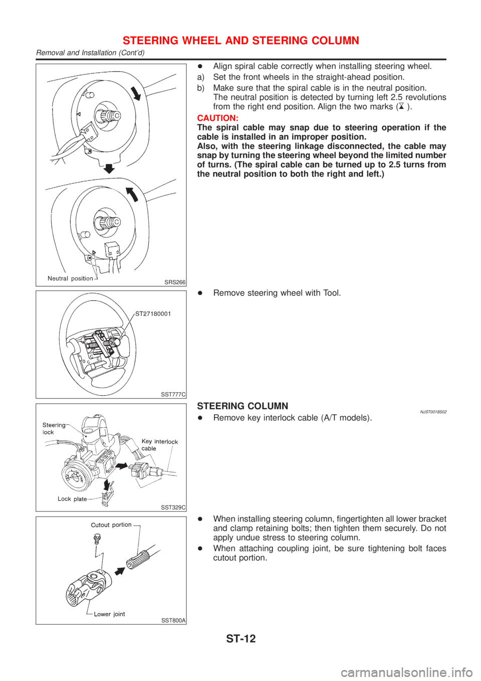
+Align spiral cable correctly when installing steering wheel.
a) Set the front wheels in the straight-ahead position.
b) Make sure that the spiral cable is in the neutral position.
The neutral position is detected by turning left 2.5 revolutions
from the right end position. Align the two marks (
).
CAUTION:
The spiral cable may snap due to steering operation if the
cable is installed in an improper position.
Also, with the steering linkage disconnected, the cable may
snap by turning the steering wheel beyond the limited number
of turns. (The spiral cable can be turned up to 2.5 turns from
the neutral position to both the right and left.)
SST777C
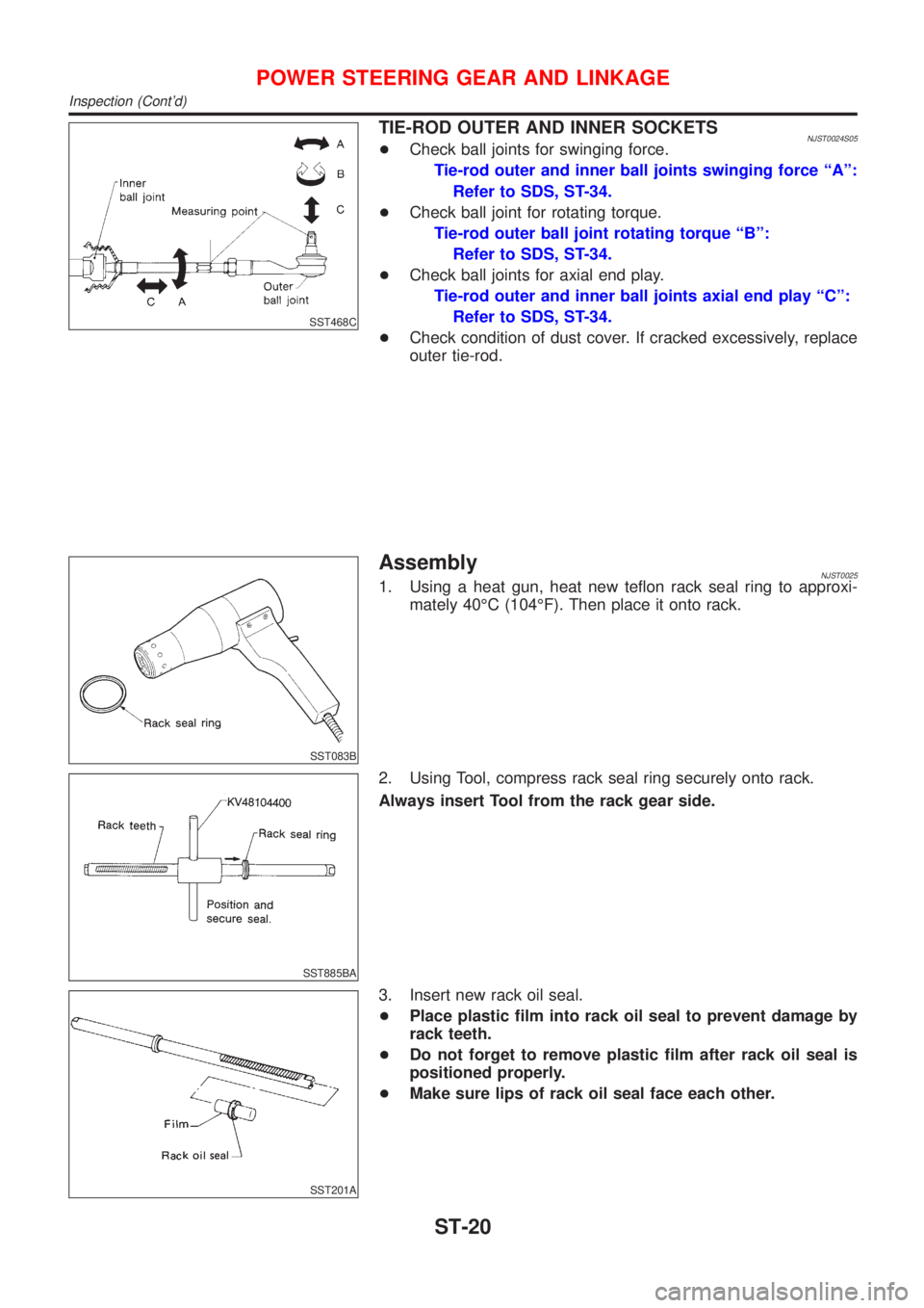
+Remove steering wheel with Tool.
SST329C
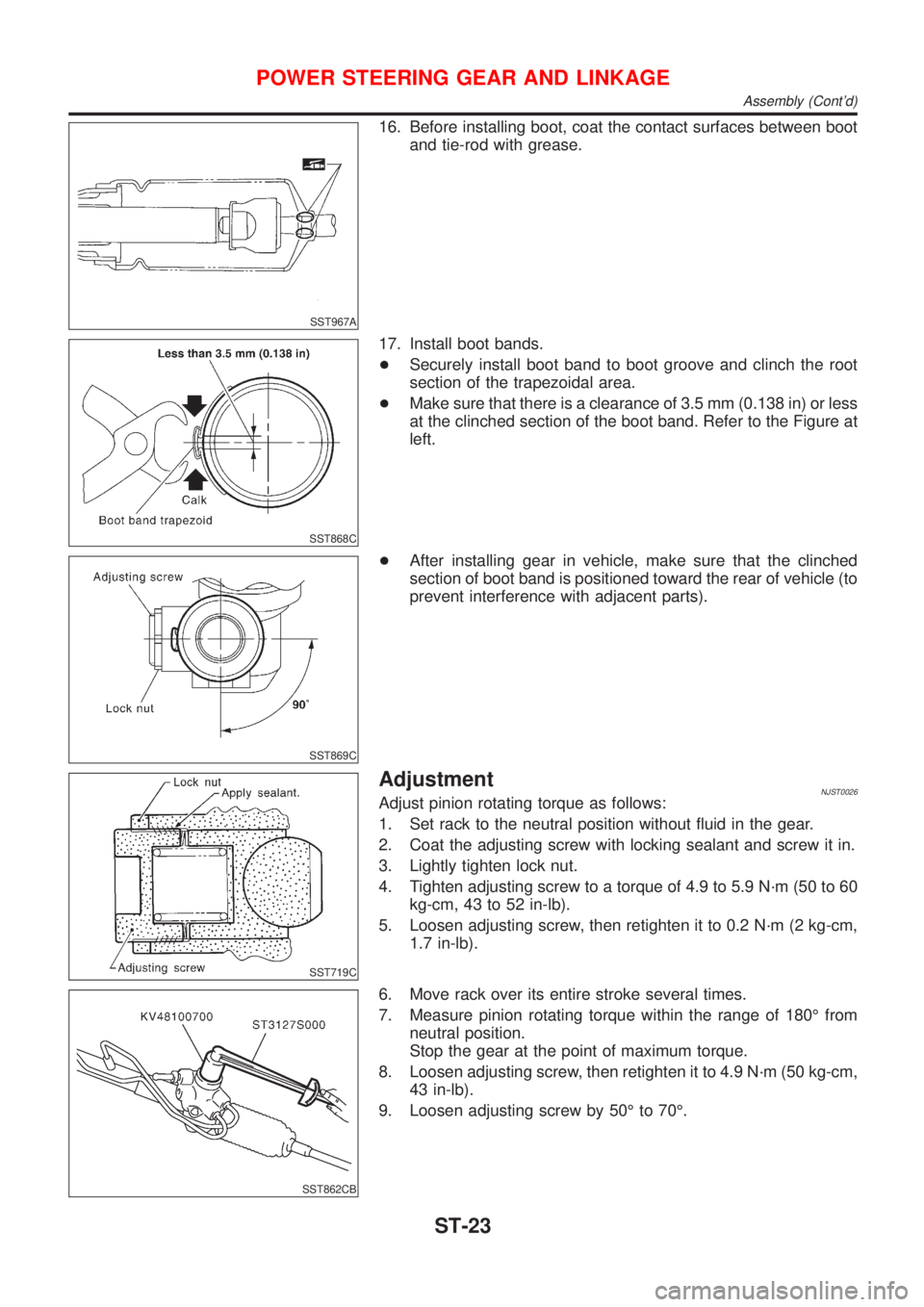
STEERING COLUMNNJST0018S02+Remove key interlock cable (A/T models).
SST800A
+When installing steering column, fingertighten all lower bracket
and clamp retaining bolts; then tighten them securely. Do not
apply undue stress to steering column.
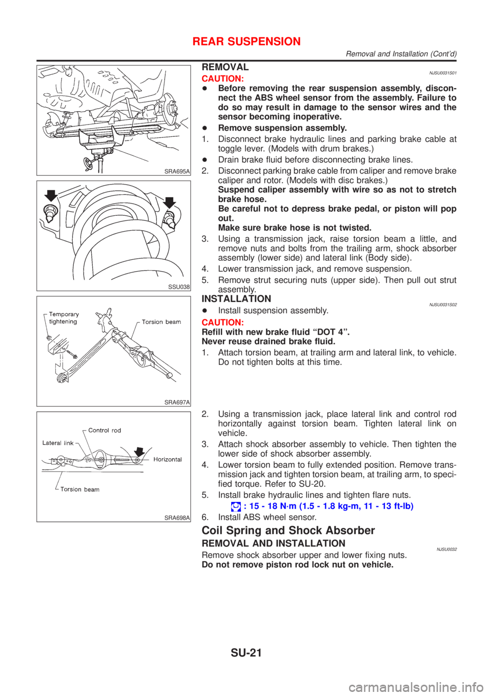
+When attaching coupling joint, be sure tightening bolt faces
cutout portion.
STEERING WHEEL AND STEERING COLUMN
Removal and Installation (Cont'd)
ST-12
Page 2856 of 2898

SST468C
TIE-ROD OUTER AND INNER SOCKETSNJST0024S05+Check ball joints for swinging force.
Tie-rod outer and inner ball joints swinging force ªAº:
Refer to SDS, ST-34.
+Check ball joint for rotating torque.
Tie-rod outer ball joint rotating torque ªBº:
Refer to SDS, ST-34.
+Check ball joints for axial end play.
Tie-rod outer and inner ball joints axial end play ªCº:
Refer to SDS, ST-34.
+Check condition of dust cover. If cracked excessively, replace
outer tie-rod.
SST083B
AssemblyNJST00251. Using a heat gun, heat new teflon rack seal ring to approxi-
mately 40ÉC (104ÉF). Then place it onto rack.
SST885BA
2. Using Tool, compress rack seal ring securely onto rack.
Always insert Tool from the rack gear side.
SST201A
3. Insert new rack oil seal.
+Place plastic film into rack oil seal to prevent damage by
rack teeth.
+Do not forget to remove plastic film after rack oil seal is
positioned properly.
+Make sure lips of rack oil seal face each other.
POWER STEERING GEAR AND LINKAGE
Inspection (Cont'd)
ST-20
Page 2857 of 2898
SST863C
4. Install center bushing and rack oil seal with rack assembly.
SST321B
5. Insert rack oil seal and end cover assembly to rack. Then
tighten end cover assembly.
SST073B
6. Fasten end cover assembly to gear housing by staking.
SST086BA
7. Set rack gear in neutral position.
Rack stroke ªSº:
Refer to SDS, ST-34.
SST880C
8. Install adjustment shims and O-rings to gear sub-assembly.
+Install the same number of adjustment shims as before,
regardless of whether or not gear sub-assembly is replaced.
+Discard old O-rings; replace with new ones.
9. Tighten gear subassembly securing bolts to specified tighten-
ing torque.
POWER STEERING GEAR AND LINKAGE
Assembly (Cont'd)
ST-21
Page 2859 of 2898

SST967A
16. Before installing boot, coat the contact surfaces between boot
and tie-rod with grease.
SST868C
17. Install boot bands.
+Securely install boot band to boot groove and clinch the root
section of the trapezoidal area.
+Make sure that there is a clearance of 3.5 mm (0.138 in) or less
at the clinched section of the boot band. Refer to the Figure at
left.
SST869C
+After installing gear in vehicle, make sure that the clinched
section of boot band is positioned toward the rear of vehicle (to
prevent interference with adjacent parts).
SST719C
AdjustmentNJST0026Adjust pinion rotating torque as follows:
1. Set rack to the neutral position without fluid in the gear.
2. Coat the adjusting screw with locking sealant and screw it in.
3. Lightly tighten lock nut.
4. Tighten adjusting screw to a torque of 4.9 to 5.9 N´m (50 to 60
kg-cm, 43 to 52 in-lb).
5. Loosen adjusting screw, then retighten it to 0.2 N´m (2 kg-cm,
1.7 in-lb).
SST862CB
6. Move rack over its entire stroke several times.
7. Measure pinion rotating torque within the range of 180É from
neutral position.
Stop the gear at the point of maximum torque.
8. Loosen adjusting screw, then retighten it to 4.9 N´m (50 kg-cm,
43 in-lb).
9. Loosen adjusting screw by 50É to 70É.
POWER STEERING GEAR AND LINKAGE
Assembly (Cont'd)
ST-23
Page 2893 of 2898

SRA695A
SSU038
REMOVALNJSU0031S01CAUTION:
+Before removing the rear suspension assembly, discon-
nect the ABS wheel sensor from the assembly. Failure to
do so may result in damage to the sensor wires and the
sensor becoming inoperative.
+Remove suspension assembly.
1. Disconnect brake hydraulic lines and parking brake cable at
toggle lever. (Models with drum brakes.)
+Drain brake fluid before disconnecting brake lines.
2. Disconnect parking brake cable from caliper and remove brake
caliper and rotor. (Models with disc brakes.)
Suspend caliper assembly with wire so as not to stretch
brake hose.
Be careful not to depress brake pedal, or piston will pop
out.
Make sure brake hose is not twisted.
3. Using a transmission jack, raise torsion beam a little, and
remove nuts and bolts from the trailing arm, shock absorber
assembly (lower side) and lateral link (Body side).
4. Lower transmission jack, and remove suspension.
5. Remove strut securing nuts (upper side). Then pull out strut
assembly.
SRA697A
INSTALLATIONNJSU0031S02+Install suspension assembly.
CAUTION:
Refill with new brake fluid ªDOT 4º.
Never reuse drained brake fluid.
1. Attach torsion beam, at trailing arm and lateral link, to vehicle.
Do not tighten bolts at this time.
SRA698A
2. Using a transmission jack, place lateral link and control rod
horizontally against torsion beam. Tighten lateral link on
vehicle.
3. Attach shock absorber assembly to vehicle. Then tighten the
lower side of shock absorber assembly.
4. Lower torsion beam to fully extended position. Remove trans-
mission jack and tighten torsion beam, at trailing arm, to speci-
fied torque. Refer to SU-20.
5. Install brake hydraulic lines and tighten flare nuts.
: 15 - 18 N´m (1.5 - 1.8 kg-m, 11 - 13 ft-lb)
6. Install ABS wheel sensor.
Coil Spring and Shock Absorber
REMOVAL AND INSTALLATIONNJSU0032Remove shock absorber upper and lower fixing nuts.
Do not remove piston rod lock nut on vehicle.
REAR SUSPENSION
Removal and Installation (Cont'd)
SU-21