Page 2529 of 2898
SLC904
4. Caulk tank in specified sequence with Tool.
SLC896
SLC897
+Use pliers in the locations where Tool cannot be used.
SLC554A
5. Make sure that the rim is completely crimped down.
Standard height ªHº:
8.0 - 8.4 mm (0.315 - 0.331 in)
6. Confirm that there is no leakage.
Refer to Inspection.
SLC933
INSPECTIONNJLC0081S041. Apply pressure with Tool.
Specified pressure value:
157 kPa (1.57 bar, 1.6 kg/cm
2, 23 psi)
WARNING:
To prevent the risk of the hose coming undone while under
pressure, securely fasten it down with a hose clamp.
Attach a hose to the oil cooler as well. (A/T model only)
ENGINE COOLING SYSTEMQG
Radiator (Aluminum type) (Cont'd)
LC-23
Page 2545 of 2898

+Replace the radiator cap if abnormalities are found with the
negative pressure valve, or if the valve opening pressure is out
of the standard range.
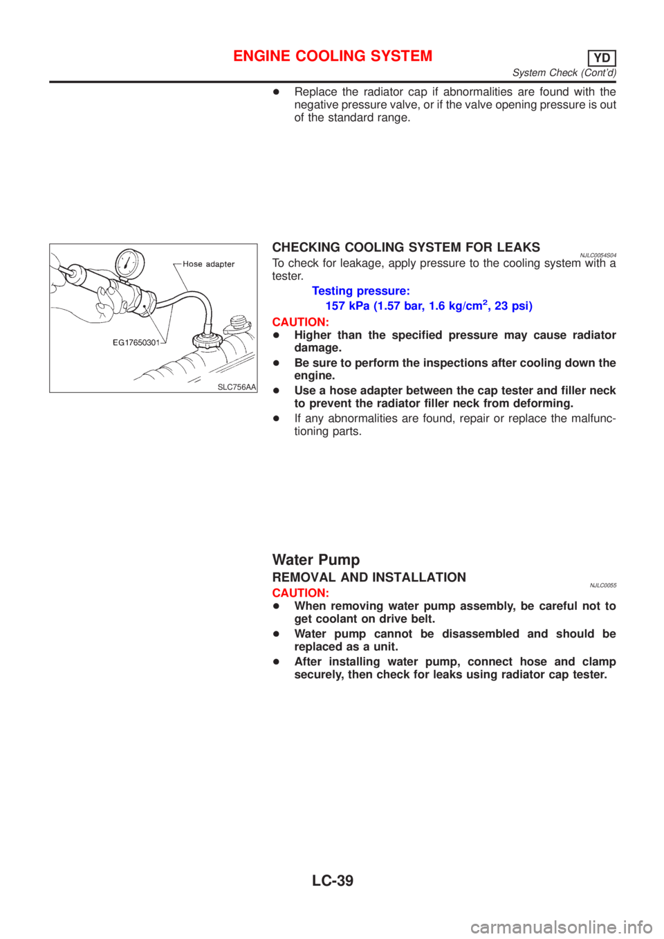
SLC756AA
CHECKING COOLING SYSTEM FOR LEAKSNJLC0054S04To check for leakage, apply pressure to the cooling system with a
tester.
Testing pressure:
157 kPa (1.57 bar, 1.6 kg/cm
2, 23 psi)
CAUTION:
+Higher than the specified pressure may cause radiator
damage.
+Be sure to perform the inspections after cooling down the
engine.
+Use a hose adapter between the cap tester and filler neck
to prevent the radiator filler neck from deforming.
+If any abnormalities are found, repair or replace the malfunc-
tioning parts.
Water Pump
REMOVAL AND INSTALLATIONNJLC0055CAUTION:
+When removing water pump assembly, be careful not to
get coolant on drive belt.
+Water pump cannot be disassembled and should be
replaced as a unit.
+After installing water pump, connect hose and clamp
securely, then check for leaks using radiator cap tester.
ENGINE COOLING SYSTEMYD
System Check (Cont'd)
LC-39
Page 2557 of 2898

NJMA0004
General maintenance includes those items which should be checked during the normal day-to-day operation
of the vehicle. They are essential if the vehicle is to continue operating properly. The owners can perform the
checks and inspections themselves or they can have their NISSAN dealers do them for a nominal charge.
OUTSIDE THE VEHICLE
The maintenance items listed here should be performed from time to time, unless otherwise specified.
Item Reference page
TiresCheck the pressure with a gauge periodically when at a service station,
including the spare, and adjust to the specified pressure if necessary. Check
carefully for damage, cuts or excessive wear.Ð
Windshield wiper
bladesCheck for cracks or wear if not functioning correctly. Ð
Doors and engine
hoodCheck that all doors, the engine hood, the trunk lid and back door operate
properly. Also ensure that all latches lock securely. Lubricate if necessary.
Make sure that the secondary latch keeps the hood from opening when the
primary latch is released.
When driving in areas using road salt or other corrosive materials, check for
lubrication frequently.BT-7
BT-16
Tire rotationTires should be rotated every 10,000 km (6,000 miles). SU-7
INSIDE THE VEHICLE
The maintenance items listed here should be checked on a regular basis, such as when performing periodic maintenance, cleaning the
vehicle, etc.
Item Reference page
LampsMake sure that the headlamps, stop lamps, tail lamps, turn signal lamps,
and other lamps are all operating properly and installed securely. Also check
headlamp aim.Ð
Warning lamps and
chimesMake sure that all warning lamps and buzzers/chimes are operating prop-
erly.Ð
Steering wheelCheck that it has the specified play.
Check for changes in the steering conditions, such as excessive free play,
hard steering or strange noises.
Free play: Less than 35 mm (1.38 in)Ð
Seat beltsCheck that all parts of the seat belt system (e.g. buckles, anchors, adjusters
and retractors) operate properly and smoothly, and are installed securely.
Check the belt webbing for cuts, fraying, wear or damage.RS-4
UNDER THE HOOD AND VEHICLE
The maintenance items listed here should be checked periodically e.g. each time you check the engine oil or refuel.
Item Reference page
Windshield washer
fluidCheck that there is adequate fluid in the tank. Ð
Engine coolant levelCheck the coolant level when the engine is cold. LC-19, LC-45
Engine oil levelCheck the level after parking the vehicle (on level ground) and turning off
the engine.LC-8, LC-31
Brake and clutch
fluid levelsMake sure that the brake and clutch fluid levels are between the ªMAXº and
ªMINº lines on the reservoir.BR-8
BatteryCheck the fluid level in each cell. It should be between the ªMAXº and ªMINº
lines.Ð
GENERAL MAINTENANCE
MA-3
Page 2595 of 2898

NJMT0008
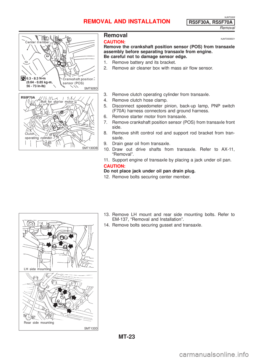
SMT928D
RemovalNJMT0008S01CAUTION:
Remove the crankshaft position sensor (POS) from transaxle
assembly before separating transaxle from engine.
Be careful not to damage sensor edge.
1. Remove battery and its bracket.
2. Remove air cleaner box with mass air flow sensor.
SMT130DB
3. Remove clutch operating cylinder from transaxle.
4. Remove clutch hose clamp.
5. Disconnect speedometer pinion, back-up lamp, PNP switch
(F70A) harness connectors and ground harness.
6. Remove starter motor from transaxle.
7. Remove crankshaft position sensor (POS) from transaxle front
side.
8. Remove shift control rod and support rod bracket from tran-
saxle.
9. Drain gear oil from transaxle.
10. Draw out drive shafts from transaxle. Refer to AX-11,
ªRemovalº.
11. Support engine of transaxle by placing a jack under oil pan.
CAUTION:
Do not place jack under oil pan drain plug.
12. Remove bolts securing center member.
SMT133D
13. Remove LH mount and rear side mounting bolts. Refer to
EM-137, ªRemoval and Installationº.
14. Remove bolts securing gusset and transaxle.
REMOVAL AND INSTALLATIONRS5F30A, RS5F70A
Removal
MT-23
Page 2598 of 2898

NJMT0090
SMT928D
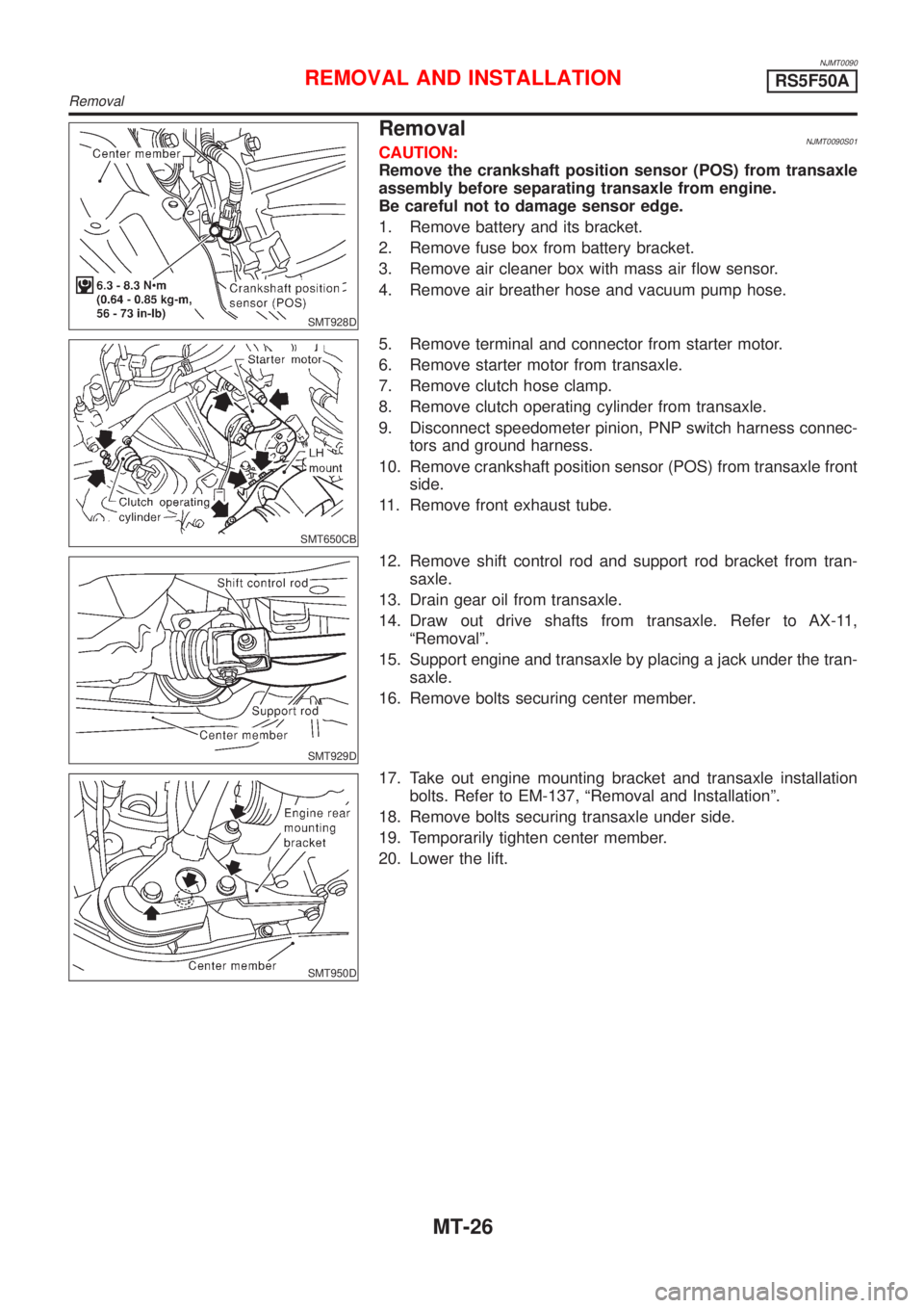
RemovalNJMT0090S01CAUTION:
Remove the crankshaft position sensor (POS) from transaxle
assembly before separating transaxle from engine.
Be careful not to damage sensor edge.
1. Remove battery and its bracket.
2. Remove fuse box from battery bracket.
3. Remove air cleaner box with mass air flow sensor.
4. Remove air breather hose and vacuum pump hose.
SMT650CB
5. Remove terminal and connector from starter motor.
6. Remove starter motor from transaxle.
7. Remove clutch hose clamp.
8. Remove clutch operating cylinder from transaxle.
9. Disconnect speedometer pinion, PNP switch harness connec-
tors and ground harness.
10. Remove crankshaft position sensor (POS) from transaxle front
side.
11. Remove front exhaust tube.
SMT929D
12. Remove shift control rod and support rod bracket from tran-
saxle.
13. Drain gear oil from transaxle.
14. Draw out drive shafts from transaxle. Refer to AX-11,
ªRemovalº.
15. Support engine and transaxle by placing a jack under the tran-
saxle.
16. Remove bolts securing center member.
SMT950D
17. Take out engine mounting bracket and transaxle installation
bolts. Refer to EM-137, ªRemoval and Installationº.
18. Remove bolts securing transaxle under side.
19. Temporarily tighten center member.
20. Lower the lift.
REMOVAL AND INSTALLATIONRS5F50A
Removal
MT-26
Page 2599 of 2898
SMT940D
SMT951D
21. Pick up EGI harness clamp and install engine slinger. Next, set
chain block.
22. Jack up the air compressor engine bracket.
23. Remove engine front mounting.
24. Remove LH side mounting. Refer to EM-137, ªRemoval and
Installationº.
SMT952D
25. Jack up until engine oil filter bracket bolts are just about to
touch the side frame.
SMT941D
26. Remove bolts securing transaxle.
27. While the transaxle is suspended, withdraw the transaxle case
from the engine without hitting suspension member.
+Open the front of the transaxle when the clutch cover
appears. Then, lower the transaxle pulling it toward the
right front.
+The spacer between the engine and transaxle should be
left at the engine side.
28. Remove spacer.
REMOVAL AND INSTALLATIONRS5F50A
Removal (Cont'd)
MT-27
Page 2713 of 2898
Front Seat Belt
REMOVAL AND INSTALLATION/4-DOOR SEDAN=NJRS00031. Slide the seat all the way forward and tilt the seatback toward the front.
2. Remove adjuster cover.
3. Remove floor anchor bolt.
4. Remove shoulder anchor bolt.
5. Remove front and rear kicking plate, then remove center pillar upper and lower garnish. Refer to BT-31,
ªSIDE AND FLOOR TRIMº for details.
6. Remove second sash guide
7. Disconnect seat belt pre-tensioner connector.
8. Remove the screw securing seat belt pre-tensioner retractor, then remove seat belt and seat belt pre-ten-
sioner retractor.
9. Remove bolts securing seat belt adjuster, then remove seat belt adjuster.
SRS812
SEAT BELTS
Front Seat Belt
RS-5
Page 2715 of 2898
REMOVAL AND INSTALLATION/5-DOOR HATCHBACK=NJRS00561. Slide the seat all the way forward and tilt the seatback toward the front.
2. Remove adjuster cover.
3. Remove floor anchor bolt.
4. Remove shoulder anchor bolt.
5. Remove front and rear kicking plate, then remove center pillar upper and lower garnish. Refer to BT-36,
ªSIDE AND FLOOR TRIMº for details.
6. Remove second sash guide
7. Disconnect seat belt pre-tensioner connector.
8. Remove the screw securing seat belt pre-tensioner retractor, then remove seat belt and seat belt pre-ten-
sioner retractor.
9. Remove bolts securing seat belt adjuster, then remove seat belt adjuster.
SRS854
SEAT BELTS
Front Seat Belt (Cont'd)
RS-7