Page 1992 of 2898
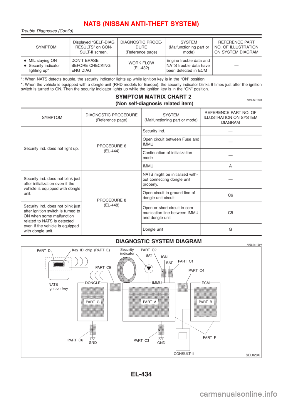
SYMPTOMDisplayed ªSELF-DIAG
RESULTSº on CON-
SULT-II screen.DIAGNOSTIC PROCE-
DURE
(Reference page)SYSTEM
(Malfunctioning part or
mode)REFERENCE PART
NO. OF ILLUSTRATION
ON SYSTEM DIAGRAM
+MIL staying ON
+Security indicator
lighting up*DON'T ERASE
BEFORE CHECKING
ENG DIAGWORK FLOW
(EL-432)Engine trouble data and
NATS trouble data have
been detected in ECMÐ
*: When NATS detects trouble, the security indicator lights up while ignition key is in the ªONº position.
*: When the vehicle is equipped with a dongle unit (RHD models for Europe), the security indicator blinks 6 times just after the ignition
switch is turned to ON. Then the security indicator lights up while the ignition key is in the ªONº position.
SYMPTOM MATRIX CHART 2NJEL0411S03(Non self-diagnosis related item)
SYMPTOMDIAGNOSTIC PROCEDURE
(Reference page)SYSTEM
(Malfunctioning part or mode)REFERENCE PART NO. OF
ILLUSTRATION ON SYSTEM
DIAGRAM
Security ind. does not light up.PROCEDURE 6
(EL-444)Security ind. Ð
Open circuit between Fuse and
IMMUÐ
Continuation of initialization
modeÐ
IMMU A
Security ind. does not blink just
after initialization even if the
vehicle is equipped with dongle
unit.
PROCEDURE 8
(EL-448)NATS might be initialized with-
out connecting dongle unit
properly.Ð
Open circuit in ground line of
dongle unit circuitC6
Security ind. does not blink just
after ignition switch is turned to
ON when some malfunction
related to NATS is detected
even if the vehicle is equipped
with dongle unit.Open or short circuit in com-
munication line between IMMU
and dongle unitC5
Dongle unit G
DIAGNOSTIC SYSTEM DIAGRAMNJEL0411S04
SEL028X
NATS (NISSAN ANTI-THEFT SYSTEM)
Trouble Diagnoses (Cont'd)
EL-434
Page 2002 of 2898
![NISSAN ALMERA 2001 Service Manual DIAGNOSTIC PROCEDURE 6=NJEL0411S10ªSECURITY INDICATOR LAMP DOES NOT LIGHT UPº
1 CHECK FUSE
Check 10A fuse [No. 12, located in the fuse block (J/B)].
Is 10A fuse OK?
Ye s©GO TO 2.
No©Replace fuse.
NISSAN ALMERA 2001 Service Manual DIAGNOSTIC PROCEDURE 6=NJEL0411S10ªSECURITY INDICATOR LAMP DOES NOT LIGHT UPº
1 CHECK FUSE
Check 10A fuse [No. 12, located in the fuse block (J/B)].
Is 10A fuse OK?
Ye s©GO TO 2.
No©Replace fuse.](/manual-img/5/57348/w960_57348-2001.png)
DIAGNOSTIC PROCEDURE 6=NJEL0411S10ªSECURITY INDICATOR LAMP DOES NOT LIGHT UPº
1 CHECK FUSE
Check 10A fuse [No. 12, located in the fuse block (J/B)].
Is 10A fuse OK?
Ye s©GO TO 2.
No©Replace fuse.
2 CHECK SECURITY INDICATOR LAMP
1. Install 10A fuse.
2. Perform initialization with CONSULT-II.
For initialization, refer to ªCONSULT-II Operation Manual NATSº.
3. Turn ignition switch OFF.
4. Start engine and turn ignition switch OFF.
5. Check the security indicator lamp lighting.
Security indicator lamp should be light up.
OK or NG
OK©INSPECTION END
NG©GO TO 3.
3 CHECK SECURITY INDICATOR LAMP POWER SUPPLY CIRCUIT
1. Disconnect security indicator lamp connector (models before VIN No. Ð N16U0135126) or Combination meter connec-
tor (models after VIN No. Ð N16U0135126).
2. Check voltage between security indicator lamp connector terminal 2 and ground (models before VIN No. Ð
N16U0135126), or Check voltage between combination meter (security indicator lamp) connector terminal 23 and
ground (models after VIN No. Ð N16U0135126).
YEL787C
OK or NG
OK©GO TO 4.
NG©Check harness for open or short between fuse and security indicator lamp (models
before VIN No. Ð N16U0135126) or Combination meter (models after VIN No. Ð
N16U0135126).
4 CHECK SECURITY INDICATOR LAMP
Check security Indicator Lamp.
Is security indicator lamp OK?
Ye s©GO TO 5.
No©Repair or replace combination meter or security indicator lamp.
NATS (NISSAN ANTI-THEFT SYSTEM)
Trouble Diagnoses (Cont'd)
EL-444
Page 2003 of 2898
5 CHECK IMMU FUNCTION
1. Connect IMMU connector.
2. Disconnect security indicator lamp connector (Sedan models and hatchback models before VIN No. Ð N16U0135126)
or combination meter connector (Hatchback models after VIN No. Ð N16U0135126).
3. Check continuity between IMMU terminal 5 (Sedan) or 6 (Hatchback) and ground.
SEL485X
OK or NG
OK©Check harness for open or short between security indicator lamp and IMMU.
NG©IMMU is malfunctioning.
Replace IMMU.Ref. part No. A
Perform initialization with CONSULT-II.
For initialization, refer to ªCONSULT-II operation manual NATSº.
NATS (NISSAN ANTI-THEFT SYSTEM)
Trouble Diagnoses (Cont'd)
EL-445
Page 2006 of 2898
DIAGNOSTIC PROCEDURE 8=NJEL0411S14
1 CHECK HARNESS CONNECTOR CONNECTION
Perform initialization with CONSULT-II.
Check harness connector connection between M31 and M102.
Then initialize NATS. For the initialization operation, refer to ªCONSULT-II operation NATSº.
Does the security indicator blink just after initialization?
Ye s©System is OK. (The malfunction is caused by improper connector connection.)
No©GO TO 2.
2 CHECK GROUND CIRCUIT FOR DONGLE UNIT
Check continuity between dongle unit terminal 1 and ground.
SEL029X
YesorNo
Ye s©GO TO 3.
No©Repair harness.
3 CHECK INTERFACE CIRCUIT
SEL030X
YesorNo
Ye s©Dongle unit is malfunctioning.
1. Replace dongle unit.
2. Perform initialization with CONSULT-II. For the initialization procedure, refer to ªCON-
SULT-II Operation Manual NATSº.
No©Repair harness.
NATS (NISSAN ANTI-THEFT SYSTEM)
Trouble Diagnoses (Cont'd)
EL-448
Page 2058 of 2898
SEF289X
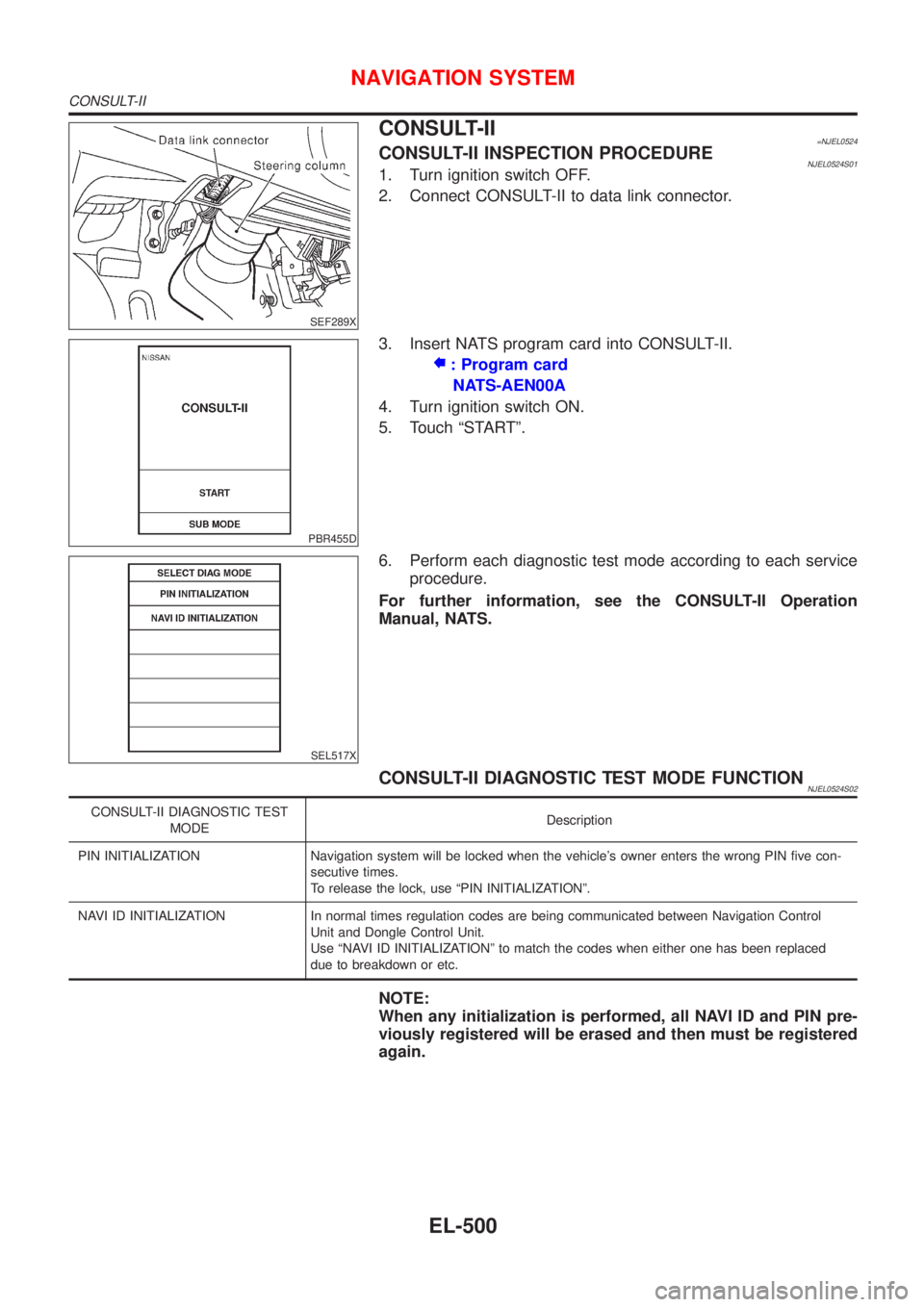
CONSULT-II=NJEL0524CONSULT-II INSPECTION PROCEDURENJEL0524S011. Turn ignition switch OFF.
2. Connect CONSULT-II to data link connector.
PBR455D
3. Insert NATS program card into CONSULT-II.
: Program card
NATS-AEN00A
4. Turn ignition switch ON.
5. Touch ªSTARTº.
SEL517X
6. Perform each diagnostic test mode according to each service
procedure.
For further information, see the CONSULT-II Operation
Manual, NATS.
CONSULT-II DIAGNOSTIC TEST MODE FUNCTIONNJEL0524S02
CONSULT-II DIAGNOSTIC TEST
MODEDescription
PIN INITIALIZATION Navigation system will be locked when the vehicle's owner enters the wrong PIN five con-
secutive times.
To release the lock, use ªPIN INITIALIZATIONº.
NAVI ID INITIALIZATION In normal times regulation codes are being communicated between Navigation Control
Unit and Dongle Control Unit.
Use ªNAVI ID INITIALIZATIONº to match the codes when either one has been replaced
due to breakdown or etc.
NOTE:
When any initialization is performed, all NAVI ID and PIN pre-
viously registered will be erased and then must be registered
again.
NAVIGATION SYSTEM
CONSULT-II
EL-500
Page 2198 of 2898
SEM933F
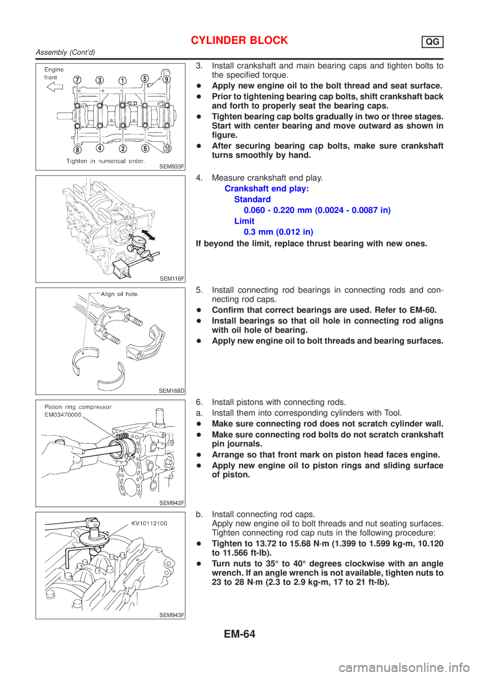
3. Install crankshaft and main bearing caps and tighten bolts to
the specified torque.
+Apply new engine oil to the bolt thread and seat surface.
+Prior to tightening bearing cap bolts, shift crankshaft back
and forth to properly seat the bearing caps.
+Tighten bearing cap bolts gradually in two or three stages.
Start with center bearing and move outward as shown in
figure.
+After securing bearing cap bolts, make sure crankshaft
turns smoothly by hand.
SEM116F
4. Measure crankshaft end play.
Crankshaft end play:
Standard
0.060 - 0.220 mm (0.0024 - 0.0087 in)
Limit
0.3 mm (0.012 in)
If beyond the limit, replace thrust bearing with new ones.
SEM168D
5. Install connecting rod bearings in connecting rods and con-
necting rod caps.
+Confirm that correct bearings are used. Refer to EM-60.
+Install bearings so that oil hole in connecting rod aligns
with oil hole of bearing.
+Apply new engine oil to bolt threads and bearing surfaces.
SEM942F
6. Install pistons with connecting rods.
a. Install them into corresponding cylinders with Tool.
+Make sure connecting rod does not scratch cylinder wall.
+Make sure connecting rod bolts do not scratch crankshaft
pin journals.
+Arrange so that front mark on piston head faces engine.
+Apply new engine oil to piston rings and sliding surface
of piston.
SEM943F
b. Install connecting rod caps.
Apply new engine oil to bolt threads and nut seating surfaces.
Tighten connecting rod cap nuts in the following procedure:
+Tighten to 13.72 to 15.68 N´m (1.399 to 1.599 kg-m, 10.120
to 11.566 ft-lb).
+Turn nuts to 35É to 40É degrees clockwise with an angle
wrench. If an angle wrench is not available, tighten nuts to
23 to 28 N´m (2.3 to 2.9 kg-m, 17 to 21 ft-lb).
CYLINDER BLOCKQG
Assembly (Cont'd)
EM-64
Page 2234 of 2898
REMOVALNJEM0094S011. Remove engine and transaxle assembly. Refer to EM-137,
ªENGINE ASSEMBLYº.
2. Remove transaxle from engine. Place engine onto engine
stand (SST). Refer to EM-141, ªCYLINDER BLOCKº, ªDisas-
semblyº.
3. Remove the following parts:
+Oil pan (upper and lower)
Refer to EM-89, ªOIL PANº.
+Oil filter bracket
Refer to LC-32, ªOil Filter Bracketº.
+Injection tube
Refer to EC-614, ªInjection Tube and Injection Nozzleº.
4. Remove secondary timing chain and associated parts.
Refer to EM-94, ªSecondary Timing Chainº.
5. When removing rear chain case, remove camshaft sprockets.
Refer to EM-120, ªCAMSHAFTº.
JEM131G
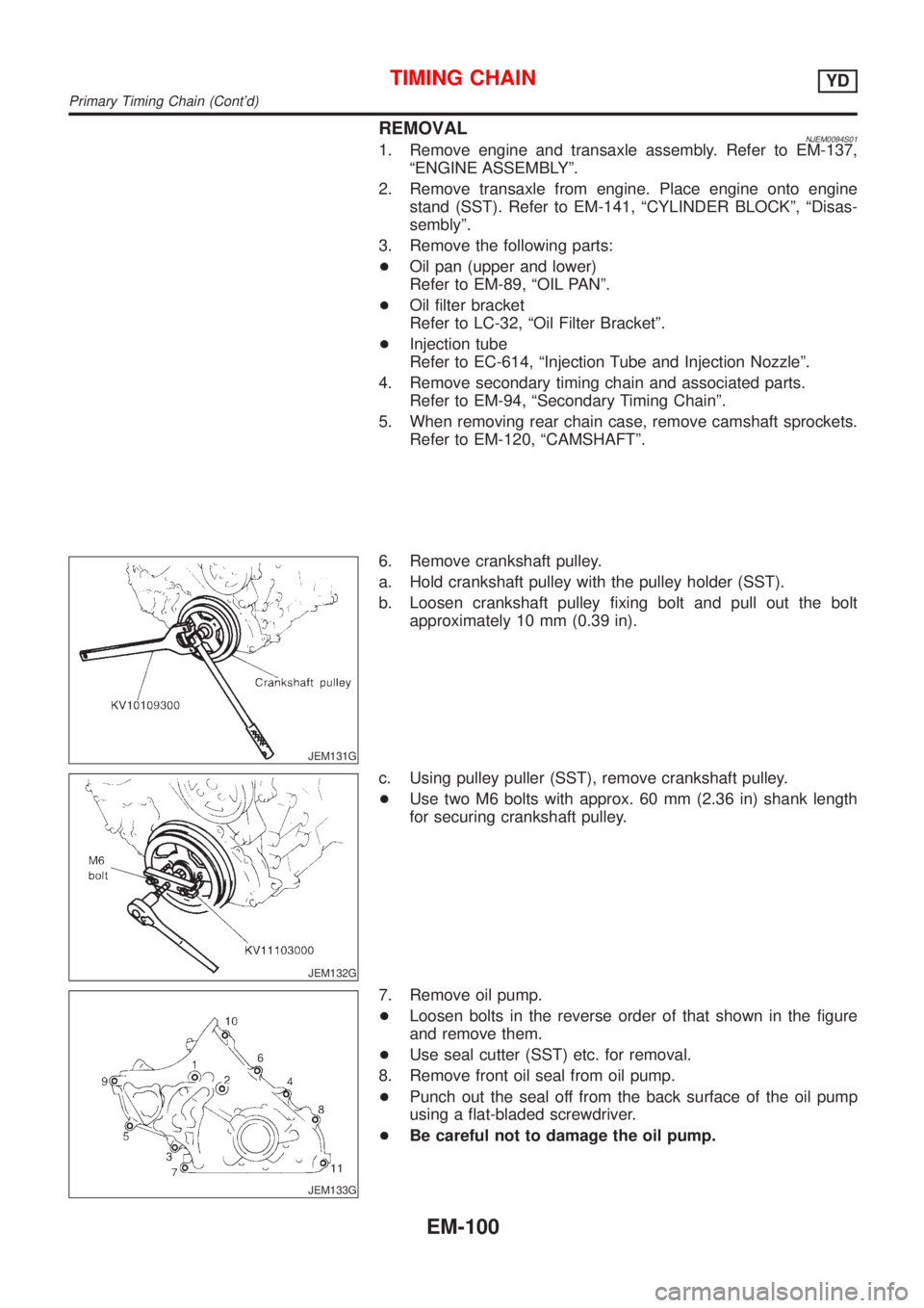
6. Remove crankshaft pulley.
a. Hold crankshaft pulley with the pulley holder (SST).
b. Loosen crankshaft pulley fixing bolt and pull out the bolt
approximately 10 mm (0.39 in).
JEM132G
c. Using pulley puller (SST), remove crankshaft pulley.
+Use two M6 bolts with approx. 60 mm (2.36 in) shank length
for securing crankshaft pulley.
JEM133G
7. Remove oil pump.
+Loosen bolts in the reverse order of that shown in the figure
and remove them.
+Use seal cutter (SST) etc. for removal.
8. Remove front oil seal from oil pump.
+Punch out the seal off from the back surface of the oil pump
using a flat-bladed screwdriver.
+Be careful not to damage the oil pump.
TIMING CHAINYD
Primary Timing Chain (Cont'd)
EM-100
Page 2261 of 2898
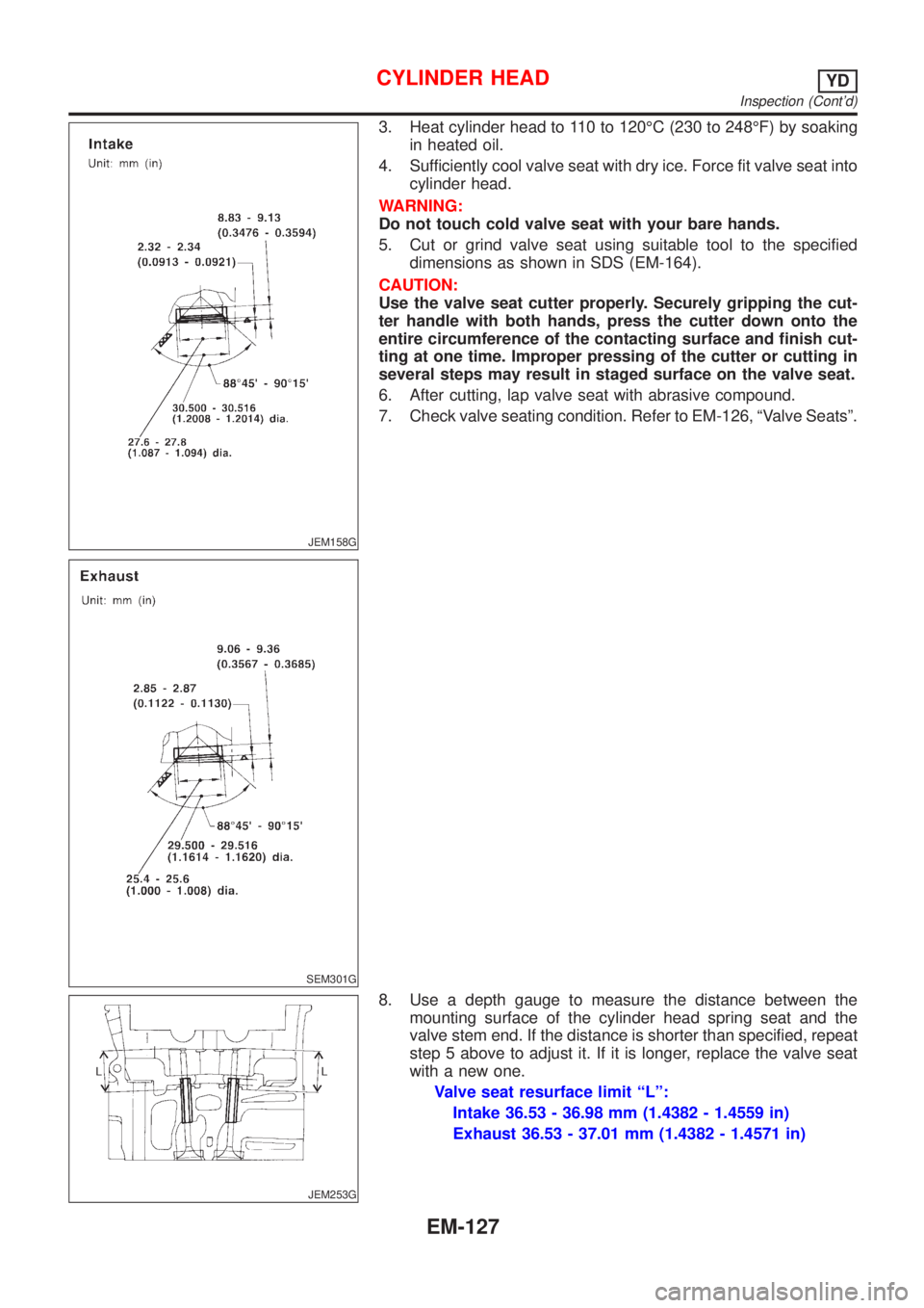
JEM158G
SEM301G
3. Heat cylinder head to 110 to 120ÉC (230 to 248ÉF) by soaking
in heated oil.
4. Sufficiently cool valve seat with dry ice. Force fit valve seat into
cylinder head.
WARNING:
Do not touch cold valve seat with your bare hands.
5. Cut or grind valve seat using suitable tool to the specified
dimensions as shown in SDS (EM-164).
CAUTION:
Use the valve seat cutter properly. Securely gripping the cut-
ter handle with both hands, press the cutter down onto the
entire circumference of the contacting surface and finish cut-
ting at one time. Improper pressing of the cutter or cutting in
several steps may result in staged surface on the valve seat.
6. After cutting, lap valve seat with abrasive compound.
7. Check valve seating condition. Refer to EM-126, ªValve Seatsº.
JEM253G
8. Use a depth gauge to measure the distance between the
mounting surface of the cylinder head spring seat and the
valve stem end. If the distance is shorter than specified, repeat
step 5 above to adjust it. If it is longer, replace the valve seat
with a new one.
Valve seat resurface limit ªLº:
Intake 36.53 - 36.98 mm (1.4382 - 1.4559 in)
Exhaust 36.53 - 37.01 mm (1.4382 - 1.4571 in)
CYLINDER HEADYD
Inspection (Cont'd)
EM-127