Page 2746 of 2898
SRS826
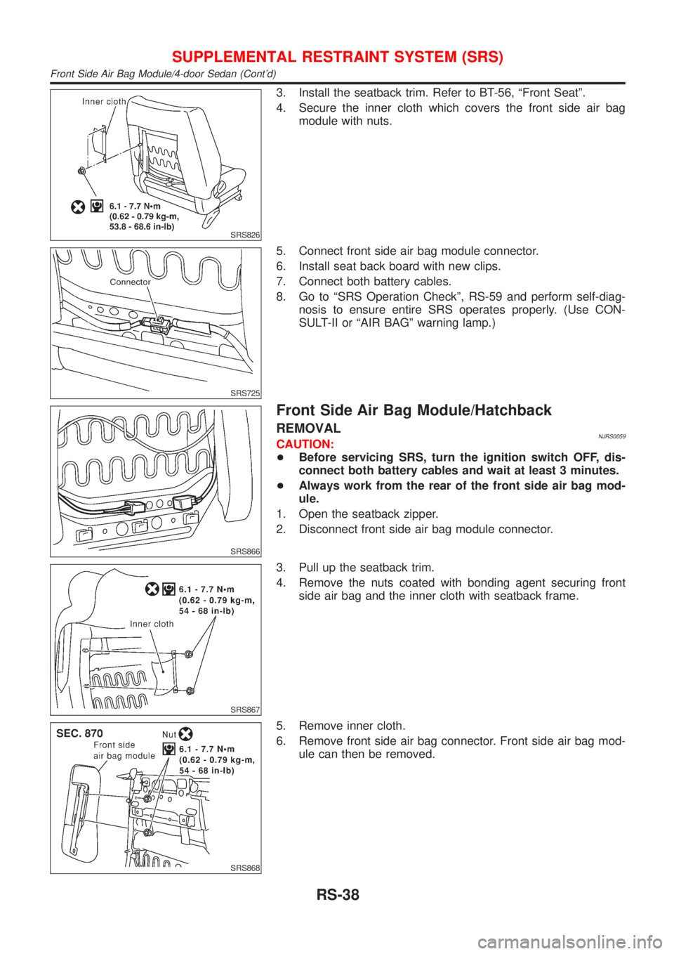
3. Install the seatback trim. Refer to BT-56, ªFront Seatº.
4. Secure the inner cloth which covers the front side air bag
module with nuts.
SRS725
5. Connect front side air bag module connector.
6. Install seat back board with new clips.
7. Connect both battery cables.
8. Go to ªSRS Operation Checkº, RS-59 and perform self-diag-
nosis to ensure entire SRS operates properly. (Use CON-
SULT-II or ªAIR BAGº warning lamp.)
SRS866
Front Side Air Bag Module/Hatchback
REMOVALNJRS0059CAUTION:
+Before servicing SRS, turn the ignition switch OFF, dis-
connect both battery cables and wait at least 3 minutes.
+Always work from the rear of the front side air bag mod-
ule.
1. Open the seatback zipper.
2. Disconnect front side air bag module connector.
SRS867
3. Pull up the seatback trim.
4. Remove the nuts coated with bonding agent securing front
side air bag and the inner cloth with seatback frame.
SRS868
5. Remove inner cloth.
6. Remove front side air bag connector. Front side air bag mod-
ule can then be removed.
SUPPLEMENTAL RESTRAINT SYSTEM (SRS)
Front Side Air Bag Module/4-door Sedan (Cont'd)
RS-38
Page 2747 of 2898
SRS869
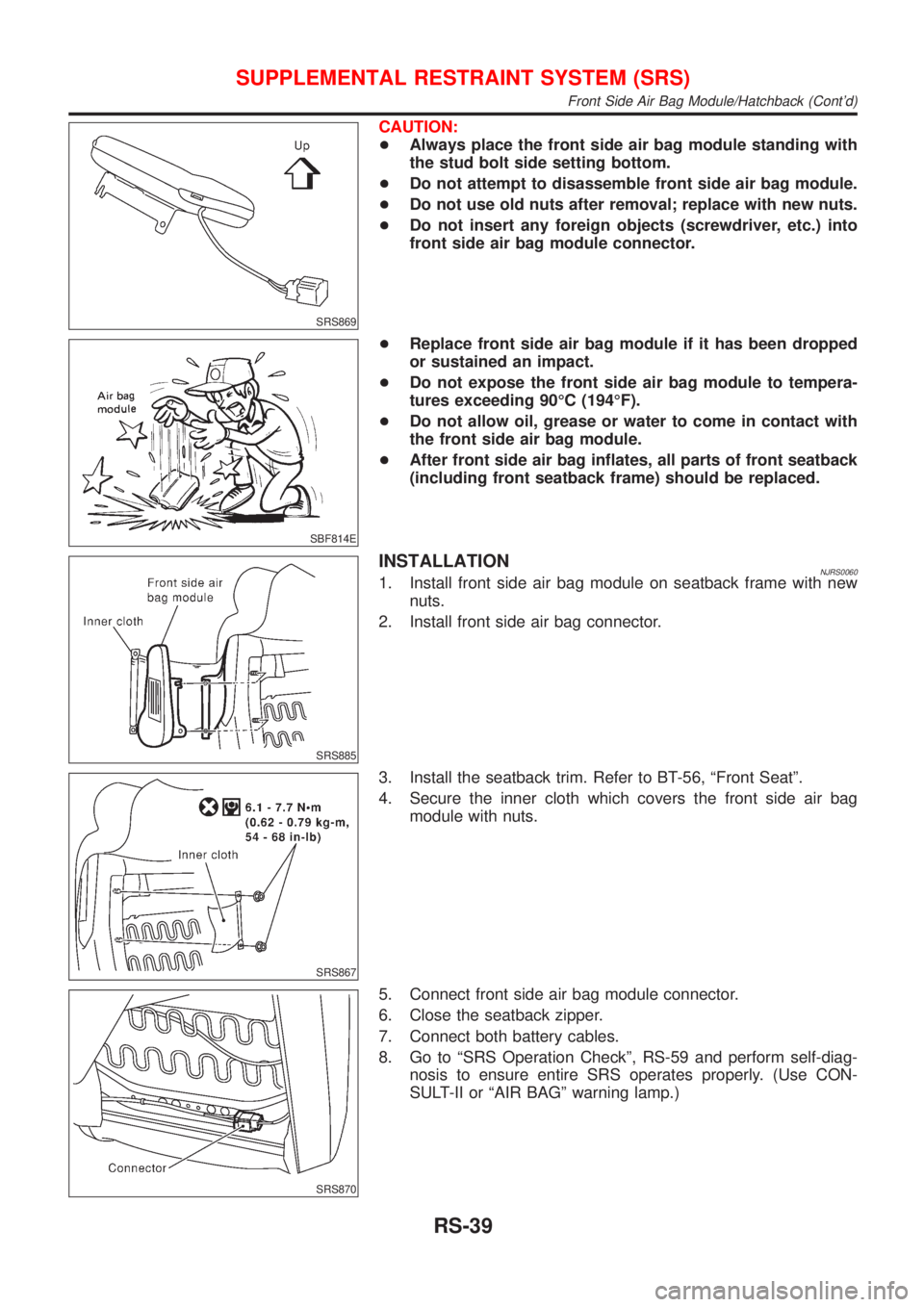
CAUTION:
+Always place the front side air bag module standing with
the stud bolt side setting bottom.
+Do not attempt to disassemble front side air bag module.
+Do not use old nuts after removal; replace with new nuts.
+Do not insert any foreign objects (screwdriver, etc.) into
front side air bag module connector.
SBF814E
+Replace front side air bag module if it has been dropped
or sustained an impact.
+Do not expose the front side air bag module to tempera-
tures exceeding 90ÉC (194ÉF).
+Do not allow oil, grease or water to come in contact with
the front side air bag module.
+After front side air bag inflates, all parts of front seatback
(including front seatback frame) should be replaced.
SRS885
INSTALLATIONNJRS00601. Install front side air bag module on seatback frame with new
nuts.
2. Install front side air bag connector.
SRS867
3. Install the seatback trim. Refer to BT-56, ªFront Seatº.
4. Secure the inner cloth which covers the front side air bag
module with nuts.
SRS870
5. Connect front side air bag module connector.
6. Close the seatback zipper.
7. Connect both battery cables.
8. Go to ªSRS Operation Checkº, RS-59 and perform self-diag-
nosis to ensure entire SRS operates properly. (Use CON-
SULT-II or ªAIR BAGº warning lamp.)
SUPPLEMENTAL RESTRAINT SYSTEM (SRS)
Front Side Air Bag Module/Hatchback (Cont'd)
RS-39
Page 2749 of 2898
SBF266H
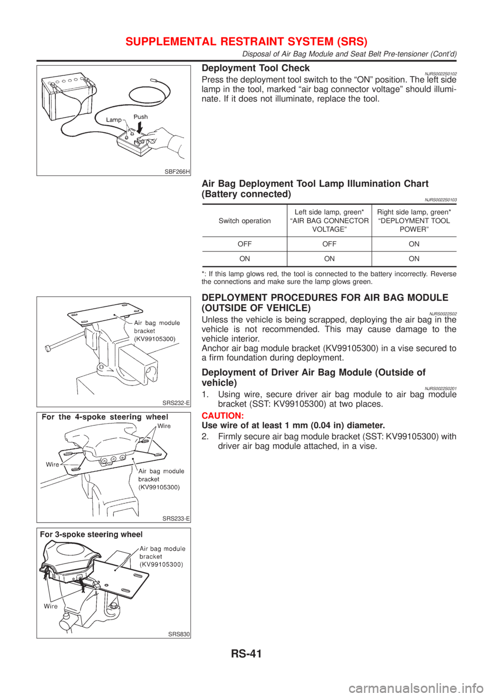
Deployment Tool CheckNJRS0022S0102Press the deployment tool switch to the ªONº position. The left side
lamp in the tool, marked ªair bag connector voltageº should illumi-
nate. If it does not illuminate, replace the tool.
Air Bag Deployment Tool Lamp Illumination Chart
(Battery connected)
NJRS0022S0103
Switch operationLeft side lamp, green*
ªAIR BAG CONNECTOR
VOLTAGEºRight side lamp, green*
ªDEPLOYMENT TOOL
POWERº
OFF OFF ON
ON ON ON
*: If this lamp glows red, the tool is connected to the battery incorrectly. Reverse
the connections and make sure the lamp glows green.
SRS232-E
SRS233-E
SRS830
DEPLOYMENT PROCEDURES FOR AIR BAG MODULE
(OUTSIDE OF VEHICLE)
NJRS0022S02Unless the vehicle is being scrapped, deploying the air bag in the
vehicle is not recommended. This may cause damage to the
vehicle interior.
Anchor air bag module bracket (KV99105300) in a vise secured to
a firm foundation during deployment.
Deployment of Driver Air Bag Module (Outside of
vehicle)
NJRS0022S02011. Using wire, secure driver air bag module to air bag module
bracket (SST: KV99105300) at two places.
CAUTION:
Use wire of at least 1 mm (0.04 in) diameter.
2. Firmly secure air bag module bracket (SST: KV99105300) with
driver air bag module attached, in a vise.
SUPPLEMENTAL RESTRAINT SYSTEM (SRS)
Disposal of Air Bag Module and Seat Belt Pre-tensioner (Cont'd)
RS-41
Page 2750 of 2898
SRS234-E
SRS831
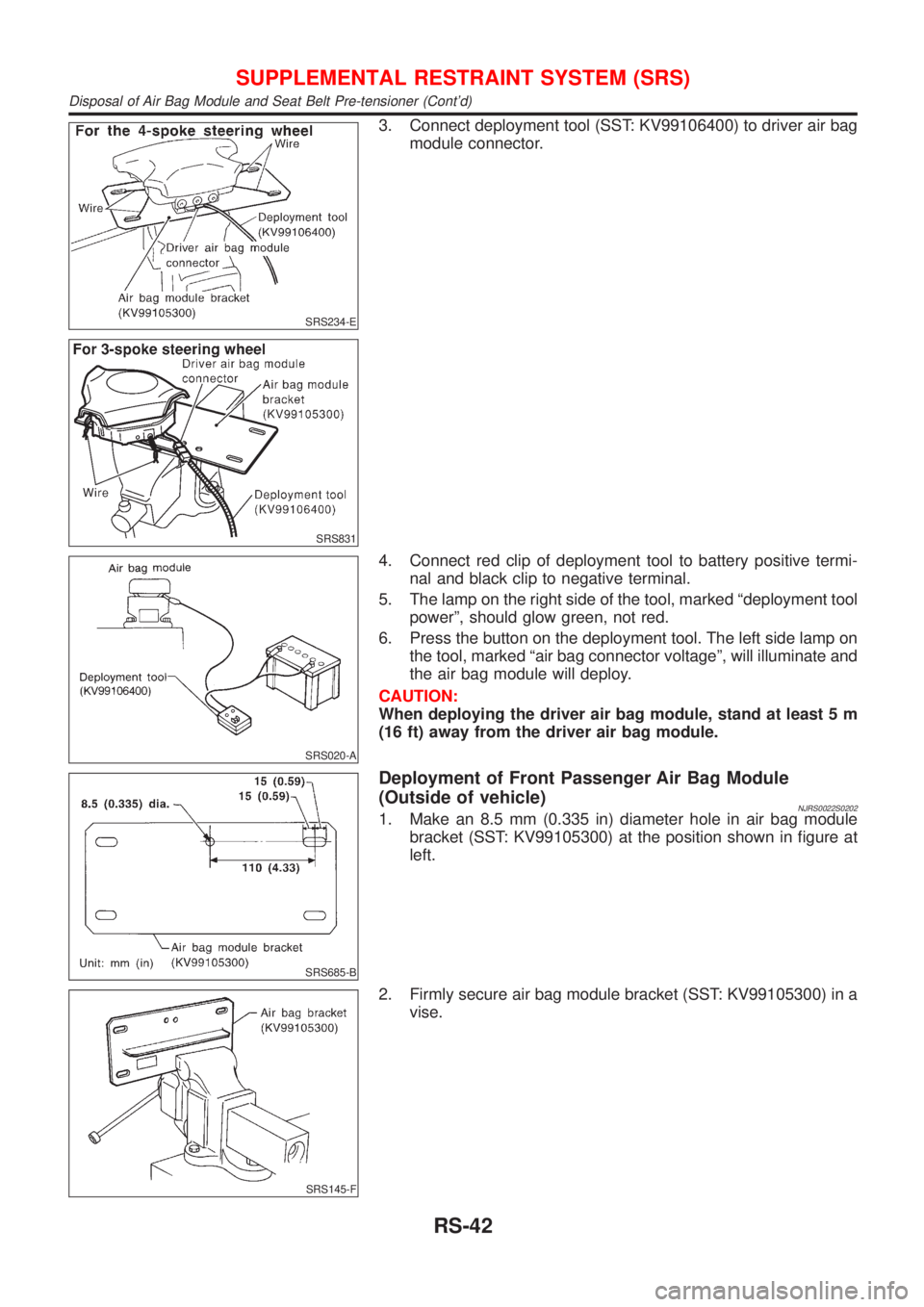
3. Connect deployment tool (SST: KV99106400) to driver air bag
module connector.
SRS020-A
4. Connect red clip of deployment tool to battery positive termi-
nal and black clip to negative terminal.
5. The lamp on the right side of the tool, marked ªdeployment tool
powerº, should glow green, not red.
6. Press the button on the deployment tool. The left side lamp on
the tool, marked ªair bag connector voltageº, will illuminate and
the air bag module will deploy.
CAUTION:
When deploying the driver air bag module, stand at least 5 m
(16 ft) away from the driver air bag module.
SRS685-B
Deployment of Front Passenger Air Bag Module
(Outside of vehicle)
NJRS0022S02021. Make an 8.5 mm (0.335 in) diameter hole in air bag module
bracket (SST: KV99105300) at the position shown in figure at
left.
SRS145-F
2. Firmly secure air bag module bracket (SST: KV99105300) in a
vise.
SUPPLEMENTAL RESTRAINT SYSTEM (SRS)
Disposal of Air Bag Module and Seat Belt Pre-tensioner (Cont'd)
RS-42
Page 2751 of 2898
![NISSAN ALMERA 2001 Service Manual SRS833
3. Match the two holes in air bag module bracket (held in vise)
and front passenger air bag module and fix them with two bolts
[M8´25 - 30 mm (0.98 - 1.18 in)].
CAUTION:
If a gap exists betwee NISSAN ALMERA 2001 Service Manual SRS833
3. Match the two holes in air bag module bracket (held in vise)
and front passenger air bag module and fix them with two bolts
[M8´25 - 30 mm (0.98 - 1.18 in)].
CAUTION:
If a gap exists betwee](/manual-img/5/57348/w960_57348-2750.png)
SRS833
3. Match the two holes in air bag module bracket (held in vise)
and front passenger air bag module and fix them with two bolts
[M8´25 - 30 mm (0.98 - 1.18 in)].
CAUTION:
If a gap exists between front passenger air bag module and air
bag module bracket, use a piece of wood inserted in the gap
to stabilize the front passenger air bag module.
SRS832
4. Connect deployment tool adapter (SST: KV99108300) to
deployment tool (SST: KV99106400) connector and front pas-
senger air bag module connector.
5. Connect red clip of deployment tool to battery positive termi-
nal and black clip to negative terminal.
6. The lamp on the right side of the tool, marked ªdeployment tool
powerº, should glow green, not red.
7. Press the button on the deployment tool. The left side lamp on
the tool, marked ªair bag connector voltageº, will illuminate and
the front passenger air bag module will deploy.
SRS020-A
CAUTION:
+When deploying the front passenger air bag module, do
not stand on the deploying side.
+Stand at least 5 m (16 ft) away from the front passenger
air bag module.
SRS490-C
Deployment of Front Side Air Bag Module (Outside of
vehicle)/4-door Sedan
NJRS0022S02031. Make 6.5 mm (0.256 in) diameter holes in air bag module
bracket (SST: KV99105300) at the position shown in figure at
left.
SRS628-B
2. Firmly secure air bag module bracket (SST: KV99105300) in a
vise.
3. Insert the stud bolts of front side air bag module into the two
holes in air bag module bracket (held in vise) and fix them with
two M6 nuts.
CAUTION:
Front side air bag module should be secured to air bag mod-
ule bracket (SST: KV99105300) in a vise with stud bolt side
setting bottom.
SUPPLEMENTAL RESTRAINT SYSTEM (SRS)
Disposal of Air Bag Module and Seat Belt Pre-tensioner (Cont'd)
RS-43
Page 2752 of 2898
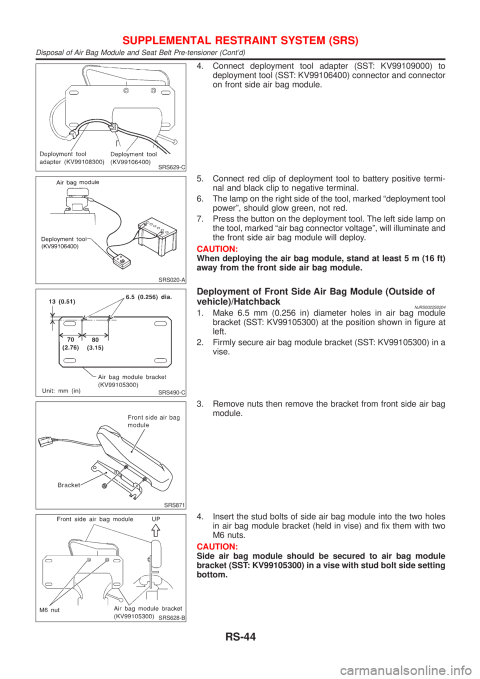
SRS629-C
4. Connect deployment tool adapter (SST: KV99109000) to
deployment tool (SST: KV99106400) connector and connector
on front side air bag module.
SRS020-A
5. Connect red clip of deployment tool to battery positive termi-
nal and black clip to negative terminal.
6. The lamp on the right side of the tool, marked ªdeployment tool
powerº, should glow green, not red.
7. Press the button on the deployment tool. The left side lamp on
the tool, marked ªair bag connector voltageº, will illuminate and
the front side air bag module will deploy.
CAUTION:
When deploying the air bag module, stand at least 5 m (16 ft)
away from the front side air bag module.
SRS490-C
Deployment of Front Side Air Bag Module (Outside of
vehicle)/Hatchback
NJRS0022S02041. Make 6.5 mm (0.256 in) diameter holes in air bag module
bracket (SST: KV99105300) at the position shown in figure at
left.
2. Firmly secure air bag module bracket (SST: KV99105300) in a
vise.
SRS871
3. Remove nuts then remove the bracket from front side air bag
module.
SRS628-B
4. Insert the stud bolts of side air bag module into the two holes
in air bag module bracket (held in vise) and fix them with two
M6 nuts.
CAUTION:
Side air bag module should be secured to air bag module
bracket (SST: KV99105300) in a vise with stud bolt side setting
bottom.
SUPPLEMENTAL RESTRAINT SYSTEM (SRS)
Disposal of Air Bag Module and Seat Belt Pre-tensioner (Cont'd)
RS-44
Page 2756 of 2898
![NISSAN ALMERA 2001 Service Manual DIAGNOSIS MODE FOR CONSULT-II=NJRS0043S02+ªSELF-DIAG [CURRENT]º
A current Self-diagnosis result (also indicated by the number of warning lamp flashes in the Diagnosis
mode) is displayed on the CONSU NISSAN ALMERA 2001 Service Manual DIAGNOSIS MODE FOR CONSULT-II=NJRS0043S02+ªSELF-DIAG [CURRENT]º
A current Self-diagnosis result (also indicated by the number of warning lamp flashes in the Diagnosis
mode) is displayed on the CONSU](/manual-img/5/57348/w960_57348-2755.png)
DIAGNOSIS MODE FOR CONSULT-II=NJRS0043S02+ªSELF-DIAG [CURRENT]º
A current Self-diagnosis result (also indicated by the number of warning lamp flashes in the Diagnosis
mode) is displayed on the CONSULT-II screen in real time. This refers to a malfunctioning part requiring
repairs.
+ªSELF-DIAG [PAST]º
Diagnosis results previously stored in the memory are displayed on the CONSULT-II screen. The stored
results are not erased until memory erasing is executed.
+ªTROUBLE DIAG RECORDº
With TROUBLE DIAG RECORD, diagnosis results previously erased by a reset operation can be displayed
on the CONSULT-II screen.
+ªECU DISCRIMINATED NO.º
The diagnosis sensor unit for each vehicle model is assigned with its own, individual classification num-
ber. This number will be displayed on the CONSULT-II screen, as shown below. When replacing the diag-
nosis sensor unit, refer to the part number for the compatibility. After installation, replacement with a cor-
rect unit can be checked by confirming this classification number on the CONSULT-II screen.
For NISSAN MODEL N16, the diagnosis sensor unit classification numbers are as follows:
DESTINATION MODEL ECU DISCRIMINATED NO.
Europe4-DOOR SEDANModels with single air bag and seat belt pre-
tensionerA50E
Models with dual air bags and seat belt pre-
tensionerA50F
Models with dual air bags, side air bag and
seat belt pre-tensionerA510
3-DOOR HATCHBACKModels with single air bag and seat belt pre-
tensionerA917
Models with dual air bags and seat belt pre-
tensionerA904
Models with dual air bags, side air bag and
seat belt pre-tensionerA905
5-DOOR HATCHBACKModels with single air bag and seat belt pre-
tensionerA917
Models with dual air bags and seat belt pre-
tensionerA904
Models with dual air bags, side air bag and
seat belt pre-tensionerA918
SUPPLEMENTAL RESTRAINT SYSTEM (SRS)
Trouble Diagnoses Introduction (Cont'd)
RS-48
Page 2794 of 2898
Part SRS is activated SRS is NOT activated
Harness and Connec-
tors1. Check connectors for poor connection, damage, and terminals for deformities.
2. Check harness for binding, chafing, cuts, or deformities.
3. If no damage is found, reinstall the harness and connectors.
4. DamagedÐREPLACE damaged section of harness. Do not attempt to repair, splice or modify any SRS
harness.
Instrument panel 1. When passenger air bag inflates, check the following points for bending, deformities or cracks.
+Opening portion for front passenger air bag
SRS837
+Front passenger air bag module brackets
SRS838
+The portions securing the instrument panel
SRS839
2. If no damage is found, reinstall the instrument panel.
3. If damagedÐREPLACE the instrument panel with bolts.
SUPPLEMENTAL RESTRAINT SYSTEM (SRS)
Collision Diagnosis (Cont'd)
RS-86