Page 333 of 2898
17. A/T Does Not Shift: D4®D3, When
Overdrive Control Switch ªONº®ªOFFº
=NJAT0347SYMPTOM:
A/T does not shift from D
4to D3when changing overdrive
control switch to ªOFFº position.
1 CHECK OVERDRIVE CONTROL SWITCH CIRCUIT
With CONSULT-II
Does ªECU INPUT SIGNALSº in ªDATA MONITORº show damage to overdrive control switch circuit?
Without CONSULT-II
Does self-diagnosis show damage to overdrive control switch circuit?
SAT344H
YesorNo
Ye s©Check overdrive control switch circuit. Refer to AT-331.
No©Go to 10. A/T Does Not Shift: D
2®D3, AT-317.
TROUBLE DIAGNOSES FOR SYMPTOMS
17. A/T Does Not Shift: D4®D3, When Overdrive Control Switch ªONº®ªOFFº
AT-331
Page 334 of 2898
18. A/T Does Not Shift: D3®22, When Selector
Lever ªDº®ª2º Position
=NJAT0348SYMPTOM:
A/T does not shift from D
3to 22when changing selector lever
from ªDº to ª2º position.
1 CHECK PNP SWITCH CIRCUIT
With CONSULT-II
Does ªECU INPUT SIGNALSº in ªDATA MONITORº show damage to PNP switch circuit?
Without CONSULT-II
Does self-diagnosis show damage to PNP switch circuit?
SAT367J
YesorNo
Ye s©Check PNP switch circuit. Refer to AT-334.
No©Go to 9. A/T Does Not Shift: D
1®D2or Does Not Kickdown: D4®D2, AT-314.
TROUBLE DIAGNOSES FOR SYMPTOMS
18. A/T Does Not Shift: D3®22, When Selector Lever ªDº®ª2º Position
AT-332
Page 335 of 2898
19. A/T Does Not Shift: 22®11, When Selector
Lever ª2º®ª1º Position
=NJAT0349SYMPTOM:
A/T does not shift from 2
2to 11when changing selector lever
from ª2º to ª1º position.
1 CHECK PNP SWITCH CIRCUIT
With CONSULT-II
Does ªECU INPUT SIGNALSº in ªDATA MONITORº show damage to PNP switch circuit?
Without CONSULT-II
Does self-diagnosis show damage to PNP switch circuit?
SAT367J
YesorNo
Ye s©Check PNP switch circuit. Refer to ª21. TCM Self-diagnosis Does Not Activate (PNP,
Overdrive Control and Throttle Position Switches Circuit Checks)º, AT-334.
No©GO TO 2.
2 CHECK SYMPTOM
Check again.
SAT778B
OK or NG
OK©INSPECTION END
NG©1. Perform TCM input/output signal inspection.
2. If NG, recheck TCM pin terminals for damage or loose connection with harness con-
nector.
TROUBLE DIAGNOSES FOR SYMPTOMS
19. A/T Does Not Shift: 22®11, When Selector Lever ª2º®ª1º Position
AT-333
Page 337 of 2898
DIAGNOSTIC PROCEDURENJAT0351S02
1 CHECK PNP SWITCH CIRCUIT (With CONSULT-II)
With CONSULT-II
1. Turn ignition switch to ªONº position.
(Do not start engine.)
2. Select ªECU INPUT SIGNALSº in ªDATA MONITORº mode for ªA/Tº with CONSULT-II.
3. Read out ªP/Nº, ªRº, ªDº, ª2º and ª1º position switches moving selector lever to each position.
Check that the signal of the selector lever position is indicated properly.
SAT701J
OK or NG
OK©GO TO 3.
NG©Check the following items:
+PNP switch (Refer to ªComponent Inspectionº, AT-341.)
+Harness for short or open between ignition switch and PNP switch (Main harness)
+Harness for short or open between PNP switch and TCM (Main harness)
+Diode (P, N positions)
TROUBLE DIAGNOSES FOR SYMPTOMS
21. TCM Self-diagnosis Does Not Activate (PNP, Overdrive Control and Throttle Position Switches Circuit Checks) (Cont'd)
AT-335
Page 339 of 2898
3 CHECK OVERDRIVE CONTROL SWITCH CIRCUIT (With CONSULT-II)
With CONSULT-II
1. Turn ignition switch to ªONº position.
(Do not start engine.)
2. Select ªECU INPUT SIGNALSº in ªDATA MONITORº mode for ªA/Tº with CONSULT-II.
3. Read out ªOVERDRIVE SWITCHº.
Check the signal of the overdrive control switch is indicated properly.
(Overdrive control switch ªONº displayed on CONSULT-II means overdrive ªOFFº.)
SAT645J
OK or NG
OK©GO TO 5.
NG©Check the following items:
+Overdrive control switch (Refer to ªComponent Inspectionº, AT-341.)
+Harness for short or open between TCM and overdrive control switch (Main harness)
+Harness of ground circuit for overdrive control switch (Main harness) for short or open
TROUBLE DIAGNOSES FOR SYMPTOMS
21. TCM Self-diagnosis Does Not Activate (PNP, Overdrive Control and Throttle Position Switches Circuit Checks) (Cont'd)
AT-337
Page 341 of 2898

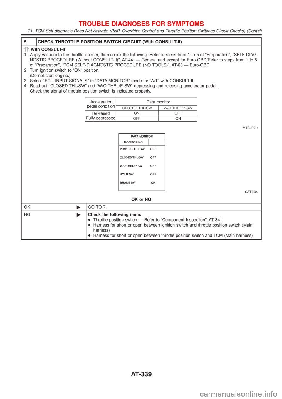
5 CHECK THROTTLE POSITION SWITCH CIRCUIT (With CONSULT-II)
With CONSULT-II
1. Apply vacuum to the throttle opener, then check the following. Refer to steps from 1 to 5 of ªPreparationº, ªSELF-DIAG-
NOSTIC PROCEDURE (Without CONSULT-II)º, AT-44. Ð General and except for Euro-OBD/Refer to steps from 1 to 5
of ªPreparationº, ªTCM SELF-DIAGNOSTIC PROCEDURE (NO TOOLS)º, AT-63 Ð Euro-OBD
2. Turn ignition switch to ªONº position.
(Do not start engine.)
3. Select ªECU INPUT SIGNALSº in ªDATA MONITORº mode for ªA/Tº with CONSULT-II.
4. Read out ªCLOSED THL/SWº and ªW/O THRL/P-SWº depressing and releasing accelerator pedal.
Check the signal of throttle position switch is indicated properly.
MTBL0011
SAT702J
OK or NG
OK©GO TO 7.
NG©Check the following items:
+Throttle position switch Ð Refer to ªComponent Inspectionº, AT-341.
+Harness for short or open between ignition switch and throttle position switch (Main
harness)
+Harness for short or open between throttle position switch and TCM (Main harness)
TROUBLE DIAGNOSES FOR SYMPTOMS
21. TCM Self-diagnosis Does Not Activate (PNP, Overdrive Control and Throttle Position Switches Circuit Checks) (Cont'd)
AT-339
Page 351 of 2898
ComponentsNJAT0107
SAT996J
CAUTION:
+Install key interlock cable in such a way that it will not be
damaged by sharp bends, twists or interference with adja-
cent parts.
+After installing key interlock cable to control device, make
sure that casing cap and bracket are firmly secured in
their positions.
SAT853J
RemovalNJAT01081. Unlock slider by squeezing lock tabs on slider from adjuster
holder and remove interlock rod from cable.
KEY INTERLOCK CABLE
Components
AT-349
Page 357 of 2898

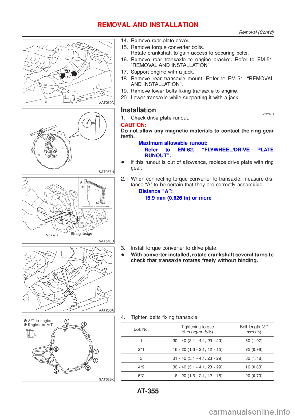
AAT259A
14. Remove rear plate cover.
15. Remove torque converter bolts.
Rotate crankshaft to gain access to securing bolts.
16. Remove rear transaxle to engine bracket. Refer to EM-51,
ªREMOVAL AND INSTALLATIONº.
17. Support engine with a jack.
18. Remove rear transaxle mount. Refer to EM-51, ªREMOVAL
AND INSTALLATIONº.
19. Remove lower bolts fixing transaxle to engine.
20. Lower transaxle while supporting it with a jack.
SAT977H
InstallationNJAT01161. Check drive plate runout.
CAUTION:
Do not allow any magnetic materials to contact the ring gear
teeth.
Maximum allowable runout:
Refer to EM-62, ªFLYWHEEL/DRIVE PLATE
RUNOUTº.
+If this runout is out of allowance, replace drive plate with ring
gear.
SAT573D
2. When connecting torque converter to transaxle, measure dis-
tance ªAº to be certain that they are correctly assembled.
Distance ªAº:
15.9 mm (0.626 in) or more
AAT266A
3. Install torque converter to drive plate.
+With converter installed, rotate crankshaft several turns to
check that transaxle rotates freely without binding.
SAT029K
4. Tighten belts fixing transaxle.
Bolt No.Tightening torque
N´m (kg-m, ft-lb)Bolt length ª!º
mm (in)
1 30 - 40 (3.1 - 4.1, 23 - 29) 50 (1.97)
2*1 16 - 20 (1.6 - 2.1, 12 - 15) 25 (0.98)
3 31 - 40 (3.1 - 4.1, 23 - 29) 30 (1.18)
4*2 30 - 40 (3.1 - 4.1, 23 - 29) 16 (0.63)
5*2 16 - 20 (1.6 - 2.1, 12 - 15) 20 (0.79)
REMOVAL AND INSTALLATION
Removal (Cont'd)
AT-355