Page 642 of 2898
SBT983
REMOVAL=NJBT0011S02+For removal of rear door finisher, refer to ªDOOR TRIMº,
BT-39.
+Remove sealing screen.
+Set the door glass in the full-close position.
1. Remove inside handle escutcheon A.
2. Remove screw securing inside handle.
3. Detach inside handle rod on the door lock assembly side.
SBT984
4. Detach lock knob rod (on the door lock assembly side).
5. Using a flat-bladed screwdriver, expand rod holder. Remove
rod from rod holder.
6. Slide inside handle backward and remove inside handle.
7. Remove rod from inside handle.
8. Remove bolts securing lower sash rear, then remove lower
sash rear.
9. Disconnect door lock actuator connector.
10. Remove screws securing door lock assembly, then remove
door lock assembly.
11. Remove bolts securing outside handle, then remove outside
handle.
DOOR
Rear Door Lock (Cont'd)
BT-24
Page 657 of 2898
Removal and InstallationNJBT0014Front door finisher
1. Remove inside handle escutcheon.
2. Remove door armrest.
3. Remove window regulator handle. (Manual models)
4. Remove power window switch finisher, then disconnect the connectors.
5. Remove bolts, screw and clip securing door finisher.
6. Remove clips securing front door finisher.
7. Lift out front door finisher.
Rear door finisher
8. Remove inside handle escutcheon.
9. Remove door armrest.
10. Remove power window switch finisher, then disconnect the connector.
11. Remove bolts and clips securing door finisher.
12. Remove clips securing rear door finisher.
13. Lift out rear door finisher.
DOOR TRIM
Removal and Installation
BT-39
Page 661 of 2898
Removal and InstallationNJBT00151. Remove rear seat. Refer to ªREAR SEATº for details, BT-60.
2. Remove shoulder anchor bolts. Refer to RS-5, ªFront Seat Beltº for details.
3. Remove front pillar garnishes, center pillar upper garnishes, center pillar lower garnishes and rear pillar
garnishes. Refer to ªSIDE AND FLOOR TRIMº for details, BT-31.
4. Push back the front seat back.
5. Remove sunroof and spot lamp switch, then disconnect connectors. (Model with sunroof)
6. Remove sunroof welt. (Model with sunroof)
7. Remove interior lamp assembly, then disconnect connectors.
8. Remove rear interior lamp assembly, then disconnect connector.(For Hatchback)
9. Remove rear seat belt center finisher.
(For Hatchback)
10. Remove sun visors.
11. Remove assist grips.
12. Remove clips securing headlining, then remove headlining from vehicle through front passenger side.
SBT055A
ROOF TRIM
Removal and Installation
BT-43
Page 684 of 2898
SBT826
Record the number of shims placed between glass lid assem-
bly and link and wire assembly. Remove securing nuts and glass
lid assembly.
SBT827
Remove screws from left and right sides of each wind deflector
holder. Extract pawls through rail holes, then remove left and right
sides of wind deflector holder. Remove screws from front end of
sunroof unit. Extract pawls through frame holes, then remove wind
deflector from frame assembly.
SBT828
CAUTION:
+Before removing sunroof motor, make sure that sunroof is
fully closed.
+After removing sunroof motor, never attempt to rotate
sunroof motor as a single unit.
SBT829
Remove shade stoppers (2 points) from rear end of sunroof
frame assembly. Remove sun shade from rear end of sunroof
frame assembly.
SUNROOF
Removal (Cont'd)
BT-66
Page 689 of 2898

SBF034BA
Removal and InstallationNJBT0023REMOVALNJBT0023S01After removing moldings, remove glass using piano wire or power
cutting tool and an inflatable pump bag.
WARNING:
When cutting the glass from the vehicle, always wear safety
glasses and heavy gloves to help prevent glass splinters from
entering your eyes or cutting your hands.
CAUTION:
+Be careful not to scratch the glass when removing.
+Do not set or stand the glass on its edge. Small chips may
develop into cracks.
SBT472
SBT473
INSTALLATIONNJBT0023S02+Use a genuine Nissan Urethane Adhesive Kit or equivalent
and follow the instructions furnished with it.
+While the urethane adhesive is curing, open a door win-
dow. This will prevent the glass from being forced out by
passenger compartment air pressure when a door is
closed.
+The molding must be installed securely so that it is in
position and leaves no gap.
+Inform the customer that the vehicle should remain sta-
tionary until the urethane adhesive has completely cured
(preferably 24 hours). Curing time varies with temperature
and humidity.
WARNING:
+Keep heat and open flames away as primers and adhesive
are flammable.
+The materials contained in the kit are harmful if
swallowed, and may irritate skin and eyes. Avoid contact
with the skin and eyes.
+Use in an open, well ventilated location. Avoid breathing
the vapors. They can be harmful if inhaled. If affected by
vapor inhalation, immediately move to an area with fresh
air.
+Driving the vehicle before the urethane adhesive has com-
pletely cured may affect the performance of the wind-
shield in case of an accident.
CAUTION:
+Do not use an adhesive which is past its usable term.
Shelf life of this product is limited to six months after the
date of manufacture. Carefully adhere to the expiration or
manufacture date printed on the box.
+Keep primers and adhesive in a cool, dry place. Ideally,
they should be stored in a refrigerator.
WINDSHIELD AND WINDOWS
Removal and Installation
BT-71
Page 716 of 2898

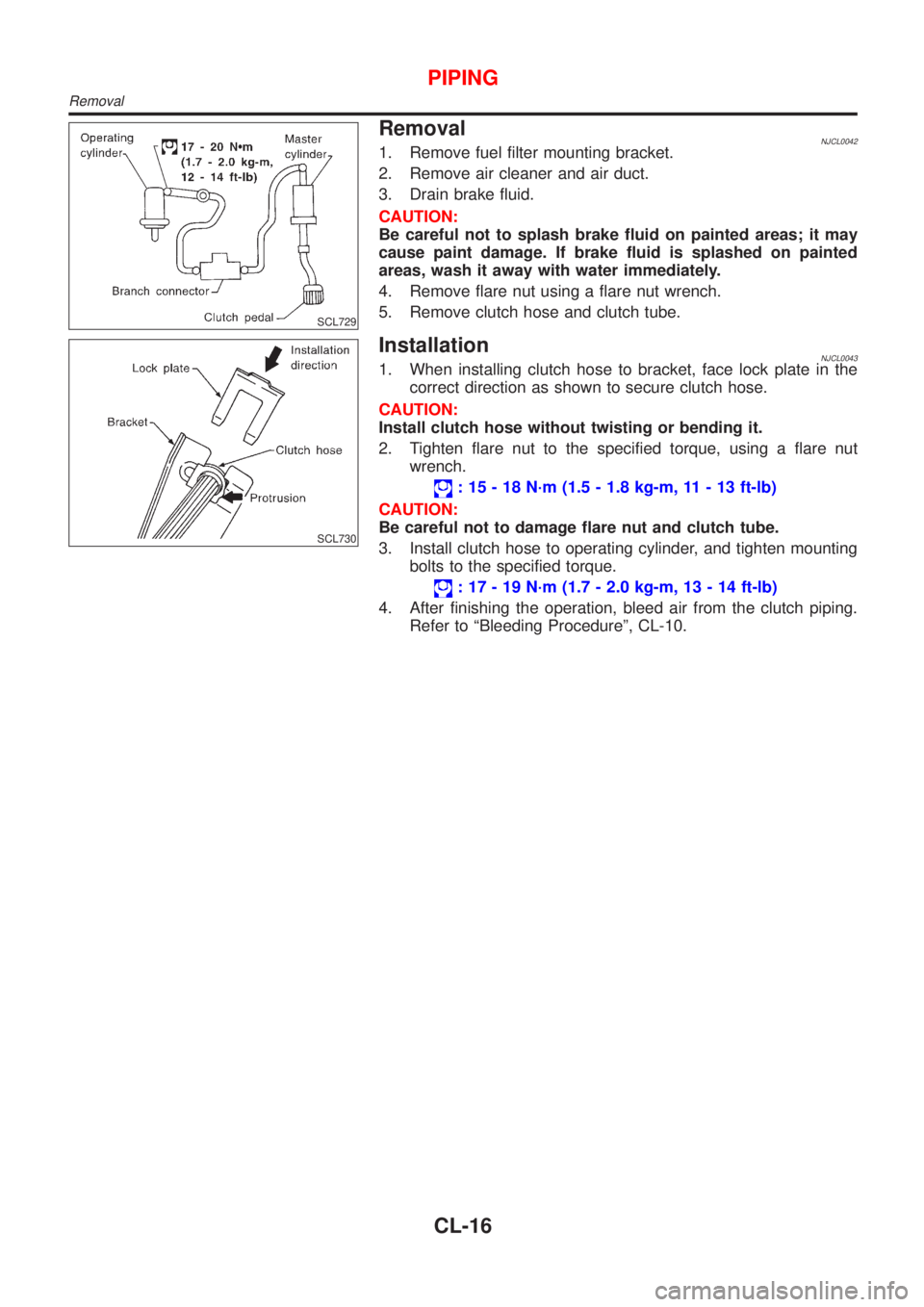
SCL729
RemovalNJCL00421. Remove fuel filter mounting bracket.
2. Remove air cleaner and air duct.
3. Drain brake fluid.
CAUTION:
Be careful not to splash brake fluid on painted areas; it may
cause paint damage. If brake fluid is splashed on painted
areas, wash it away with water immediately.
4. Remove flare nut using a flare nut wrench.
5. Remove clutch hose and clutch tube.
SCL730
InstallationNJCL00431. When installing clutch hose to bracket, face lock plate in the
correct direction as shown to secure clutch hose.
CAUTION:
Install clutch hose without twisting or bending it.
2. Tighten flare nut to the specified torque, using a flare nut
wrench.
: 15 - 18 N´m (1.5 - 1.8 kg-m, 11 - 13 ft-lb)
CAUTION:
Be careful not to damage flare nut and clutch tube.
3. Install clutch hose to operating cylinder, and tighten mounting
bolts to the specified torque.
: 17 - 19 N´m (1.7 - 2.0 kg-m, 13 - 14 ft-lb)
4. After finishing the operation, bleed air from the clutch piping.
Refer to ªBleeding Procedureº, CL-10.
PIPING
Removal
CL-16
Page 718 of 2898

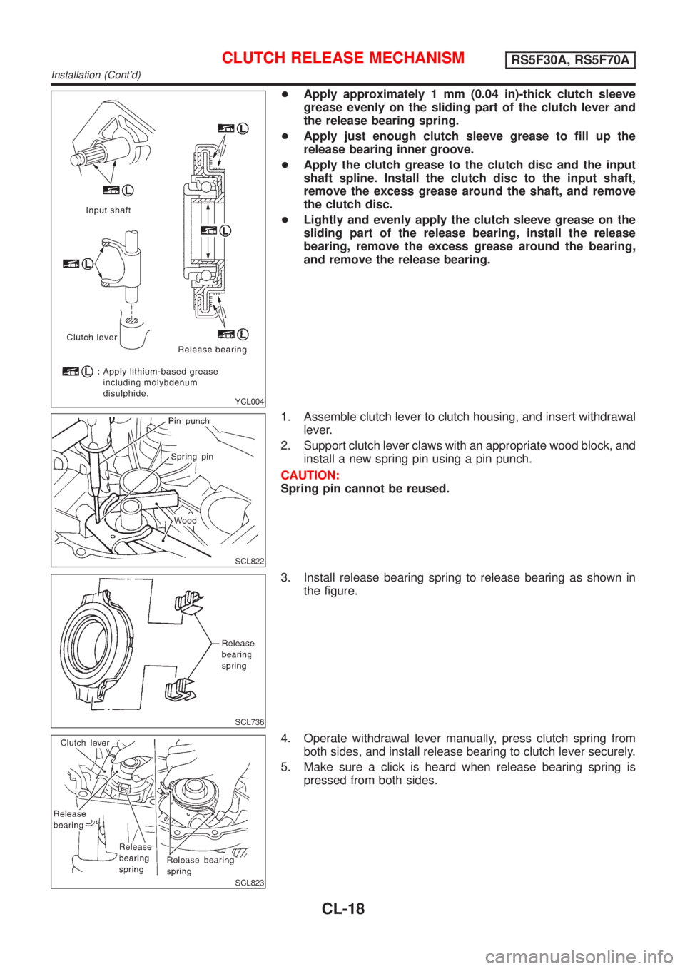
YCL004
+Apply approximately 1 mm (0.04 in)-thick clutch sleeve
grease evenly on the sliding part of the clutch lever and
the release bearing spring.
+Apply just enough clutch sleeve grease to fill up the
release bearing inner groove.
+Apply the clutch grease to the clutch disc and the input
shaft spline. Install the clutch disc to the input shaft,
remove the excess grease around the shaft, and remove
the clutch disc.
+Lightly and evenly apply the clutch sleeve grease on the
sliding part of the release bearing, install the release
bearing, remove the excess grease around the bearing,
and remove the release bearing.
SCL822
1. Assemble clutch lever to clutch housing, and insert withdrawal
lever.
2. Support clutch lever claws with an appropriate wood block, and
install a new spring pin using a pin punch.
CAUTION:
Spring pin cannot be reused.
SCL736
3. Install release bearing spring to release bearing as shown in
the figure.
SCL823
4. Operate withdrawal lever manually, press clutch spring from
both sides, and install release bearing to clutch lever securely.
5. Make sure a click is heard when release bearing spring is
pressed from both sides.
CLUTCH RELEASE MECHANISMRS5F30A, RS5F70A
Installation (Cont'd)
CL-18
Page 740 of 2898

Supplemental Restraint System (SRS) ªAIR
BAGº and ªSEAT BELT PRE-TENSIONERº
NJEC0002The Supplemental Restraint System such as ªAIR BAGº and ªSEAT BELT PRE-TENSIONERº used along with
a seat belt, helps to reduce the risk or severity of injury to the driver and front passenger for certain types of
collision. The SRS system composition which is available to NISSAN MODEL N16 is as follows (The compo-
sition varies according to the destination and optional equipment.):
+For a frontal collision
The Supplemental Restraint System consists of driver air bag module (located in the center of the steer-
ing wheel), front passenger air bag module (located on the instrument panel on passenger side), front seat
belt pre-tensioners, a diagnoses sensor unit, warning lamp, wiring harness and spiral cable.
+For a side collision
The Supplemental Restraint System consists of front side air bag module (located in the outer side of front
seat), side air bag (satellite) sensor, diagnoses sensor unit (one of components of air bags for a frontal
collision), wiring harness, warning lamp (one of components of air bags for a frontal collision).
Information necessary to service the system safely is included in theRS sectionof this Service Manual.
WARNING:
+To avoid rendering the SRS inoperative, which could increase the risk of personal injury or death
in the event of a collision which would result in air bag inflation, all maintenance should be per-
formed by an authorized NISSAN dealer.
+Improper maintenance, including incorrect removal and installation of the SRS, can lead to per-
sonal injury caused by unintentional activation of the system. For removal of Spiral Cable and Air
Bag Module, see the RS section.
+Do not use electrical test equipment on any circuit related to the SRS unless instructed to in this
Service Manual. SRS wiring harness can be identified by yellow harness connector.
Precautions for On Board Diagnostic (OBD)
System of Engine and A/T
NJEC0003The ECM has an on board diagnostic system. It will light up the malfunction indicator (MI) to warn the driver
of a malfunction causing emission deterioration.
CAUTION:
+Be sure to turn the ignition switch ªOFFº and disconnect the negative battery terminal before any
repair or inspection work. The open/short circuit of related switches, sensors, solenoid valves, etc.
will cause the MI to light up.
+Be sure to connect and lock the connectors securely after work. A loose (unlocked) connector will
cause the MI to light up due to the open circuit. (Be sure the connector is free from water, grease,
dirt, bent terminals, etc.)
+Certain systems and components, especially those related to OBD, may use a new style slide-
locking type harness connector.
For description and how to disconnect, refer to EL section, ªDescriptionº, ªHARNESS CONNEC-
TORº.
+Be sure to route and secure the harnesses properly after work. The interference of the harness with
a bracket, etc. may cause the MI to light up due to the short circuit.
+Be sure to connect rubber tubes properly after work. A misconnected or disconnected rubber tube
may cause the MI to light up due to the malfunction of fuel injection system, etc.
+Be sure to erase the unnecessary malfunction information (repairs completed) from the ECM and
TCM (Transmission Control Module) before returning the vehicle to the customer.
PRECAUTIONSQG
Supplemental Restraint System (SRS) ªAIR BAGº and ªSEAT BELT PRE-TENSIONERº
EC-16