Page 341 of 2898
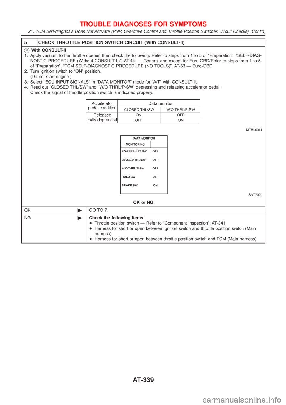
5 CHECK THROTTLE POSITION SWITCH CIRCUIT (With CONSULT-II)
With CONSULT-II
1. Apply vacuum to the throttle opener, then check the following. Refer to steps from 1 to 5 of ªPreparationº, ªSELF-DIAG-
NOSTIC PROCEDURE (Without CONSULT-II)º, AT-44. Ð General and except for Euro-OBD/Refer to steps from 1 to 5
of ªPreparationº, ªTCM SELF-DIAGNOSTIC PROCEDURE (NO TOOLS)º, AT-63 Ð Euro-OBD
2. Turn ignition switch to ªONº position.
(Do not start engine.)
3. Select ªECU INPUT SIGNALSº in ªDATA MONITORº mode for ªA/Tº with CONSULT-II.
4. Read out ªCLOSED THL/SWº and ªW/O THRL/P-SWº depressing and releasing accelerator pedal.
Check the signal of throttle position switch is indicated properly.
MTBL0011
SAT702J
OK or NG
OK©GO TO 7.
NG©Check the following items:
+Throttle position switch Ð Refer to ªComponent Inspectionº, AT-341.
+Harness for short or open between ignition switch and throttle position switch (Main
harness)
+Harness for short or open between throttle position switch and TCM (Main harness)
TROUBLE DIAGNOSES FOR SYMPTOMS
21. TCM Self-diagnosis Does Not Activate (PNP, Overdrive Control and Throttle Position Switches Circuit Checks) (Cont'd)
AT-339
Page 342 of 2898
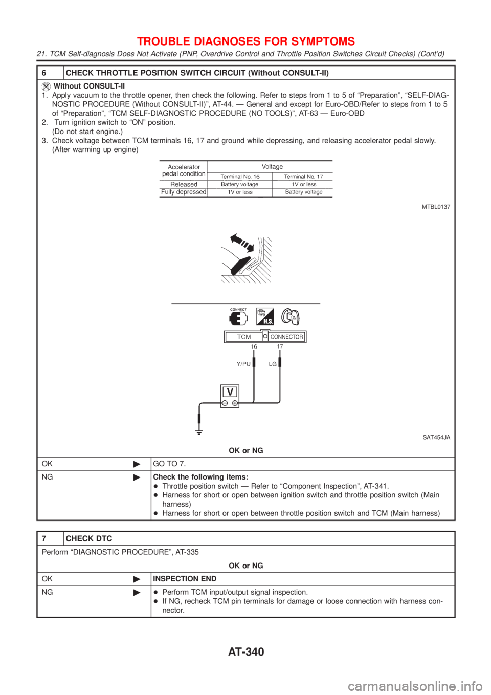
6 CHECK THROTTLE POSITION SWITCH CIRCUIT (Without CONSULT-II)
Without CONSULT-II
1. Apply vacuum to the throttle opener, then check the following. Refer to steps from 1 to 5 of ªPreparationº, ªSELF-DIAG-
NOSTIC PROCEDURE (Without CONSULT-II)º, AT-44. Ð General and except for Euro-OBD/Refer to steps from 1 to 5
of ªPreparationº, ªTCM SELF-DIAGNOSTIC PROCEDURE (NO TOOLS)º, AT-63 Ð Euro-OBD
2. Turn ignition switch to ªONº position.
(Do not start engine.)
3. Check voltage between TCM terminals 16, 17 and ground while depressing, and releasing accelerator pedal slowly.
(After warming up engine)
MTBL0137
SAT454JA
OK or NG
OK©GO TO 7.
NG©Check the following items:
+Throttle position switch Ð Refer to ªComponent Inspectionº, AT-341.
+Harness for short or open between ignition switch and throttle position switch (Main
harness)
+Harness for short or open between throttle position switch and TCM (Main harness)
7 CHECK DTC
Perform ªDIAGNOSTIC PROCEDUREº, AT-335
OK or NG
OK©INSPECTION END
NG©+Perform TCM input/output signal inspection.
+If NG, recheck TCM pin terminals for damage or loose connection with harness con-
nector.
TROUBLE DIAGNOSES FOR SYMPTOMS
21. TCM Self-diagnosis Does Not Activate (PNP, Overdrive Control and Throttle Position Switches Circuit Checks) (Cont'd)
AT-340
Page 347 of 2898
Diagnostic ProcedureNJAT0105SYMPTOM 1:
+Selector lever cannot be moved from ªPº position with key
in ON position and brake pedal applied.
+Selector lever can be moved from ªPº position with key in
ON position and brake pedal released.
+Selector lever can be moved from ªPº position when key
is removed from key cylinder.
SYMPTOM 2:
Ignition key cannot be removed when selector lever is set to
ªPº position. It can be removed when selector lever is set to
any position except ªPº.
1 CHECK KEY INTERLOCK CABLE
Check key interlock cable for damage.
OK or NG
OK©GO TO 2.
NG©Repair key interlock cable. Refer to AT-349.
2 CHECK SELECTOR LEVER POSITION
Check selector lever position for damage.
OK or NG
OK©GO TO 3.
NG©Check selector lever. Refer to ªON-VEHICLE SERVICE Ð PNP Switch and Control
Cable Adjustmentº, AT-352.
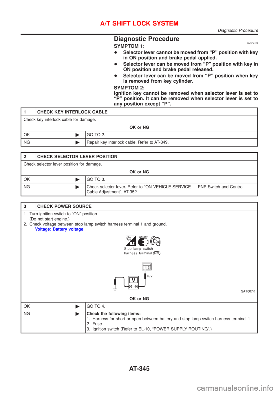
3 CHECK POWER SOURCE
1. Turn ignition switch to ªONº position.
(Do not start engine.)
2. Check voltage between stop lamp switch harness terminal 1 and ground.
Voltage: Battery voltage
SAT007K
OK or NG
OK©GO TO 4.
NG©Check the following items:
1. Harness for short or open between battery and stop lamp switch harness terminal 1
2. Fuse
3. Ignition switch (Refer to EL-10, ªPOWER SUPPLY ROUTINGº.)
A/T SHIFT LOCK SYSTEM
Diagnostic Procedure
AT-345
Page 348 of 2898
4 CHECK INPUT SIGNAL (A/T DEVICE)
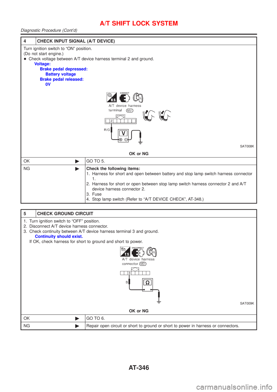
Turn ignition switch to ªONº position.
(Do not start engine.)
+Check voltage between A/T device harness terminal 2 and ground.
Voltage:
Brake pedal depressed:
Battery voltage
Brake pedal released:
0V
SAT008K
OK or NG
OK©GO TO 5.
NG©Check the following items:
1. Harness for short and open between battery and stop lamp switch harness connector
1.
2. Harness for short or open between stop lamp switch harness connector 2 and A/T
device harness connector 2.
3. Fuse
4. Stop lamp switch (Refer to ªA/T DEVICE CHECKº, AT-348.)
5 CHECK GROUND CIRCUIT
1. Turn ignition switch to ªOFFº position.
2. Disconnect A/T device harness connector.
3. Check continuity between A/T device harness terminal 3 and ground.
Continuity should exist.
If OK, check harness for short to ground and short to power.
SAT009K
OK or NG
OK©GO TO 6.
NG©Repair open circuit or short to ground or short to power in harness or connectors.
A/T SHIFT LOCK SYSTEM
Diagnostic Procedure (Cont'd)
AT-346
Page 349 of 2898
6 CHECK RELAY CIRCUIT
1. Turn ignition switch to ON.
+Check voltage between terminal4-3and2-3.
SAT010K
OK or NG
OK©GO TO 7.
NG©Replace A/T device.
7 CHECK PARK POSITION SWITCH
Refer to ªA/T device Checkº, AT-348.
OK or NG
OK©GO TO 8.
NG©Replace A/T device.
8 CHECK SHIFT LOCK SOLENOID
Refer to ªA/T device Checkº, AT-348.
OK or NG
OK©GO TO 9.
NG©Replace A/T device.
9 SHIFT LOCK OPERATION
1. Reconnect shift lock harness connector.
2. Turn ignition switch from ªOFFº to ªONº position. (Do not start engine.)
3. Recheck shift lock operation.
OK or NG
OK©INSPECTION END
NG©1. Perform A/T device input/output signal inspection test.
2. If NG, recheck harness connector connection.
A/T SHIFT LOCK SYSTEM
Diagnostic Procedure (Cont'd)
AT-347
Page 356 of 2898
SAT065K
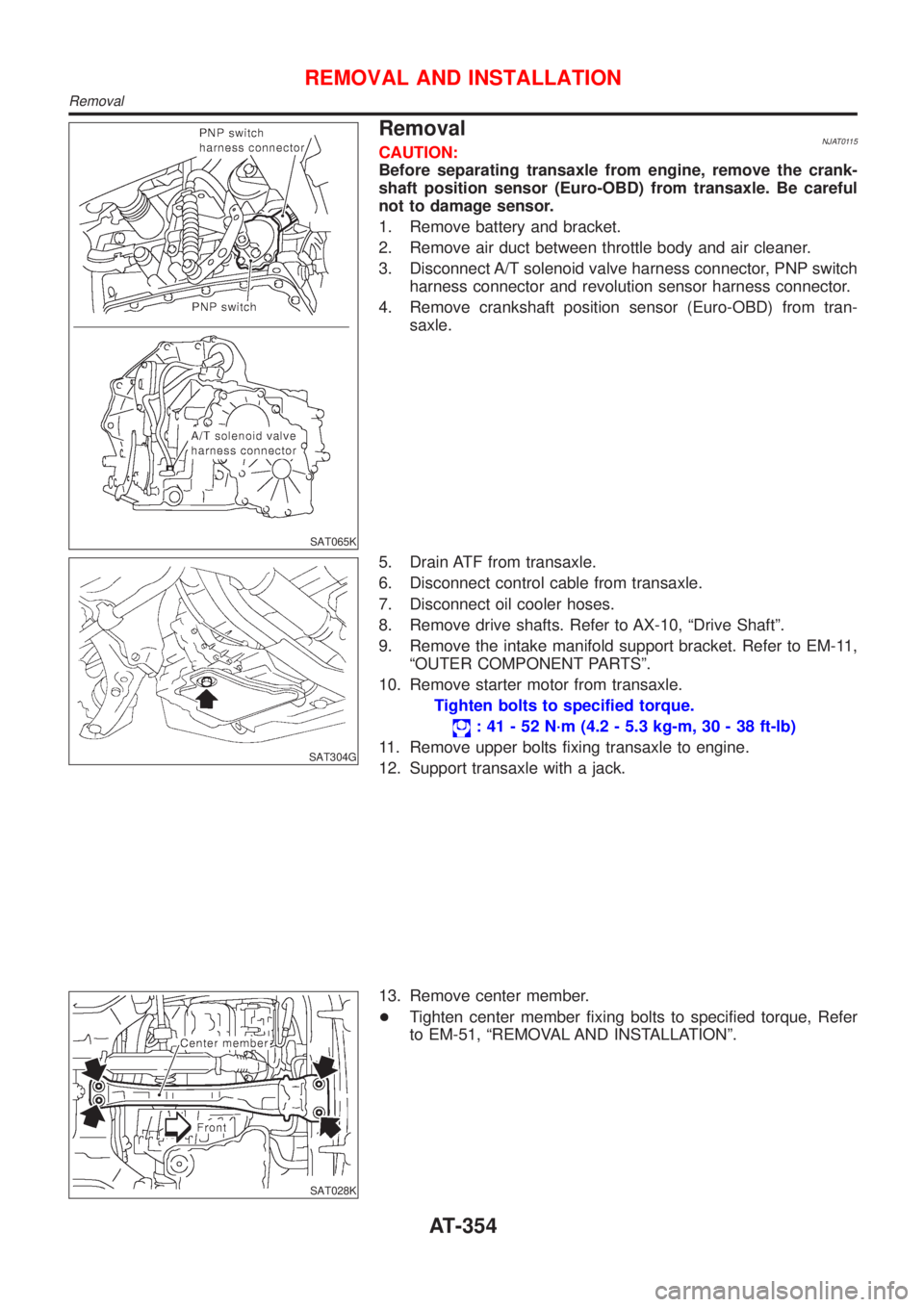
RemovalNJAT0115CAUTION:
Before separating transaxle from engine, remove the crank-
shaft position sensor (Euro-OBD) from transaxle. Be careful
not to damage sensor.
1. Remove battery and bracket.
2. Remove air duct between throttle body and air cleaner.
3. Disconnect A/T solenoid valve harness connector, PNP switch
harness connector and revolution sensor harness connector.
4. Remove crankshaft position sensor (Euro-OBD) from tran-
saxle.
SAT304G
5. Drain ATF from transaxle.
6. Disconnect control cable from transaxle.
7. Disconnect oil cooler hoses.
8. Remove drive shafts. Refer to AX-10, ªDrive Shaftº.
9. Remove the intake manifold support bracket. Refer to EM-11,
ªOUTER COMPONENT PARTSº.
10. Remove starter motor from transaxle.
Tighten bolts to specified torque.
: 41 - 52 N´m (4.2 - 5.3 kg-m, 30 - 38 ft-lb)
11. Remove upper bolts fixing transaxle to engine.
12. Support transaxle with a jack.
SAT028K
13. Remove center member.
+Tighten center member fixing bolts to specified torque, Refer
to EM-51, ªREMOVAL AND INSTALLATIONº.
REMOVAL AND INSTALLATION
Removal
AT-354
Page 357 of 2898
AAT259A
14. Remove rear plate cover.
15. Remove torque converter bolts.
Rotate crankshaft to gain access to securing bolts.
16. Remove rear transaxle to engine bracket. Refer to EM-51,
ªREMOVAL AND INSTALLATIONº.
17. Support engine with a jack.
18. Remove rear transaxle mount. Refer to EM-51, ªREMOVAL
AND INSTALLATIONº.
19. Remove lower bolts fixing transaxle to engine.
20. Lower transaxle while supporting it with a jack.
SAT977H
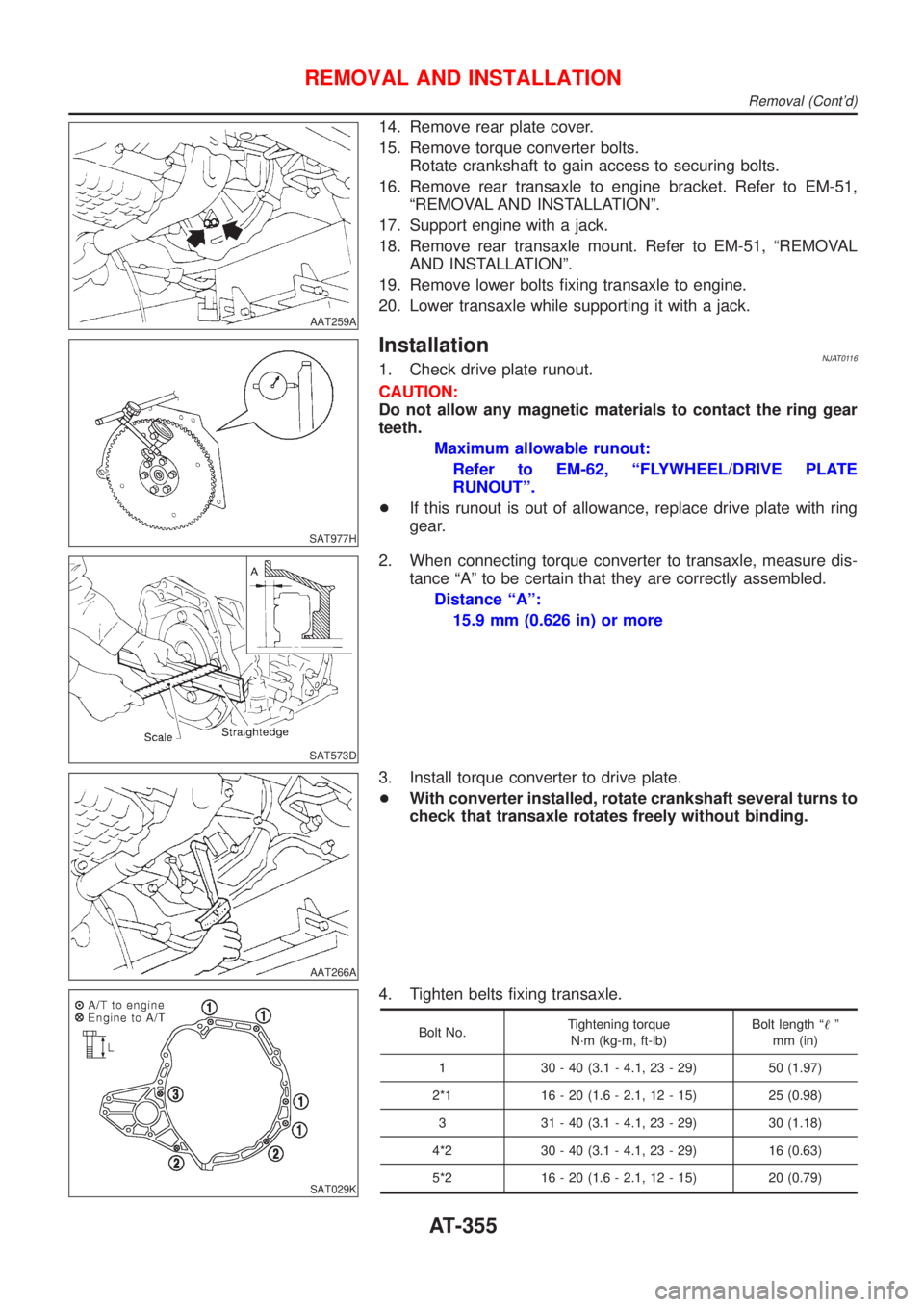
InstallationNJAT01161. Check drive plate runout.
CAUTION:
Do not allow any magnetic materials to contact the ring gear
teeth.
Maximum allowable runout:
Refer to EM-62, ªFLYWHEEL/DRIVE PLATE
RUNOUTº.
+If this runout is out of allowance, replace drive plate with ring
gear.
SAT573D
2. When connecting torque converter to transaxle, measure dis-
tance ªAº to be certain that they are correctly assembled.
Distance ªAº:
15.9 mm (0.626 in) or more
AAT266A
3. Install torque converter to drive plate.
+With converter installed, rotate crankshaft several turns to
check that transaxle rotates freely without binding.
SAT029K
4. Tighten belts fixing transaxle.
Bolt No.Tightening torque
N´m (kg-m, ft-lb)Bolt length ª!º
mm (in)
1 30 - 40 (3.1 - 4.1, 23 - 29) 50 (1.97)
2*1 16 - 20 (1.6 - 2.1, 12 - 15) 25 (0.98)
3 31 - 40 (3.1 - 4.1, 23 - 29) 30 (1.18)
4*2 30 - 40 (3.1 - 4.1, 23 - 29) 16 (0.63)
5*2 16 - 20 (1.6 - 2.1, 12 - 15) 20 (0.79)
REMOVAL AND INSTALLATION
Removal (Cont'd)
AT-355
Page 358 of 2898
SAT058K
*1: With gusset to A/T
*2: With gusset to cylinder block
SAT638A
5. Reinstall any part removed.
6. Adjust control cable. Refer to AT-352.
7. Check continuity of PNP switch. Refer to AT-334.
8. Refill transaxle with ATF and check fluid level.
9. Move selector lever through all positions to be sure that tran-
saxle operates correctly. With parking brake applied, idle
engine. Move selector lever through ªNº to ªDº, to ª2º, to ª1º and
ªRº positions. A slight shock should be felt through the hand
gripping the selector each time the transaxle is shifted.
10. Perform road test. Refer to AT-85.
REMOVAL AND INSTALLATION
Installation (Cont'd)
AT-356