Page 582 of 2898
PBR455D
5. Stop vehicle with engine running and touch ªSTARTº on CON-
SULT-II screen.
PBR385C
6. Touch ªABSº.
PST412B
7. Touch ªSELF-DIAG RESULTSº.
+The screen shows the detected malfunction and how many
times the ignition switch has been turned since the malfunc-
tion.
8. Make the necessary repairs following the diagnostic proce-
dures.
SBR561E
9. After the malfunctions are repaired, erase the self-diagnostic
results stored in the control unit by touching ªERASEº.
10. Check ABS warning lamp for deactivation after driving vehicle
over 30 km/h (19 MPH) for at least one minute.
NOTE:
ªSELF-DIAG RESULTSº screen shows the detected malfunction
and how many times the ignition switch has been turned since the
malfunction.
ON BOARD DIAGNOSTIC SYSTEM DESCRIPTIONABS
CONSULT-II Inspection Procedure (Cont'd)
BR-66
Page 585 of 2898
PBR455D
ACTIVE TEST PROCEDURENJBR0093S04+When conducting Active test, vehicle must be stationary.
+When ABS warning lamp stays on, never conduct Active test.
1. Turn ignition switch OFF.
2. Connect CONSULT-II to data link connector.
3. Start engine.
4. Touch ªSTARTº on CONSULT-II screen.
PBR385C
5. Touch ªABSº.
PST412B
6. Touch ªACTIVE TESTº.
PBR976C
7. Select active test item by touching screen.
PBR934C
8. Touch ªSTARTº.
9. Carry out the active test by touching screen key.
ON BOARD DIAGNOSTIC SYSTEM DESCRIPTIONABS
CONSULT-II Inspection Procedure (Cont'd)
BR-69
Page 586 of 2898

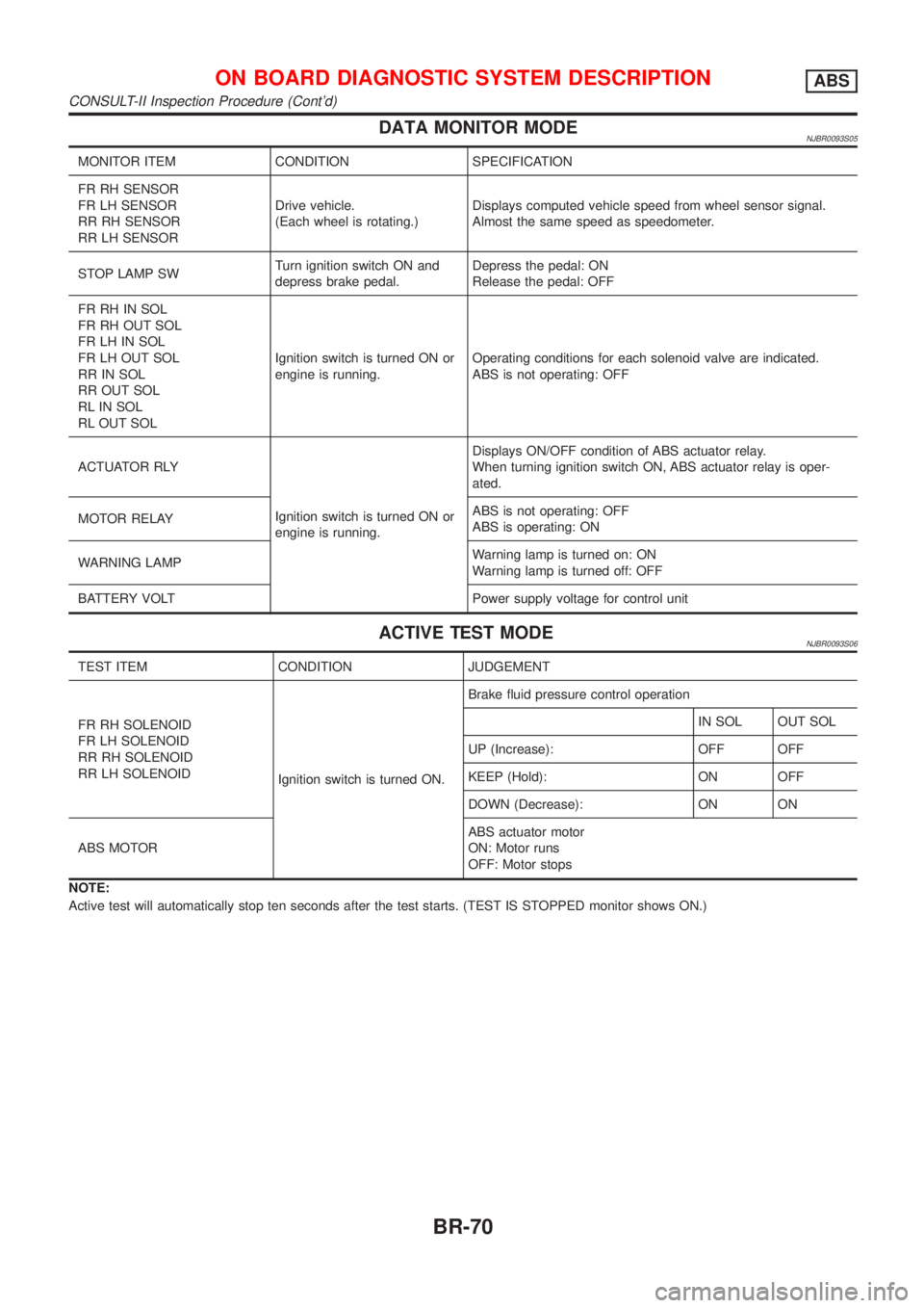
DATA MONITOR MODENJBR0093S05
MONITOR ITEM CONDITION SPECIFICATION
FR RH SENSOR
FR LH SENSOR
RR RH SENSOR
RR LH SENSORDrive vehicle.
(Each wheel is rotating.)Displays computed vehicle speed from wheel sensor signal.
Almost the same speed as speedometer.
STOP LAMP SWTurn ignition switch ON and
depress brake pedal.Depress the pedal: ON
Release the pedal: OFF
FR RH IN SOL
FR RH OUT SOL
FR LH IN SOL
FR LH OUT SOL
RR IN SOL
RR OUT SOL
RL IN SOL
RL OUT SOLIgnition switch is turned ON or
engine is running.Operating conditions for each solenoid valve are indicated.
ABS is not operating: OFF
ACTUATOR RLY
Ignition switch is turned ON or
engine is running.Displays ON/OFF condition of ABS actuator relay.
When turning ignition switch ON, ABS actuator relay is oper-
ated.
MOTOR RELAYABS is not operating: OFF
ABS is operating: ON
WARNING LAMPWarning lamp is turned on: ON
Warning lamp is turned off: OFF
BATTERY VOLT Power supply voltage for control unit
ACTIVE TEST MODENJBR0093S06
TEST ITEM CONDITION JUDGEMENT
FR RH SOLENOID
FR LH SOLENOID
RR RH SOLENOID
RR LH SOLENOID
Ignition switch is turned ON.Brake fluid pressure control operation
IN SOL OUT SOL
UP (Increase): OFF OFF
KEEP (Hold): ON OFF
DOWN (Decrease): ON ON
ABS MOTORABS actuator motor
ON: Motor runs
OFF: Motor stops
NOTE:
Active test will automatically stop ten seconds after the test starts. (TEST IS STOPPED monitor shows ON.)
ON BOARD DIAGNOSTIC SYSTEM DESCRIPTIONABS
CONSULT-II Inspection Procedure (Cont'd)
BR-70
Page 590 of 2898
5 RECHECK BRAKE FLUID LEVEL
Check brake fluid level in reservoir tank again.
SBR451D
Is brake fluid filled between MAX and MIN lines on reservoir tank and/or has brake fluid been contaminated?
Ye s©GO TO 6.
No©Fill up brake fluid.
6 CHECK WARNING LAMP ACTIVATION
Check warning lamp activation.
SBR759E
Does warning lamp turn on when ignition switch is turned ªONº?
Ye s©GO TO 7.
No©Check fuse, warning lamp bulb and warning lamp circuit.
7 CHECK WARNING LAMP DEACTIVATION
Check warning lamp for deactivation after engine is started.
Does warning lamp turn off when engine is started?
Ye s©GO TO 8.
No©Go to Self-diagnosis. Refer to BR-63, 65.
8 DRIVE VEHICLE
Drive vehicle at speeds over 30 km/h (19 MPH) for at least one minute.
Does warning lamp remain off after vehicle has been driven at 30 km/h (19 MPH) for at least one minute?
Ye s©END
No©Go to Self-diagnosis. Refer to BR-63, 65.
TROUBLE DIAGNOSIS Ð BASIC INSPECTIONABS
Preliminary Check (Cont'd)
BR-74
Page 603 of 2898

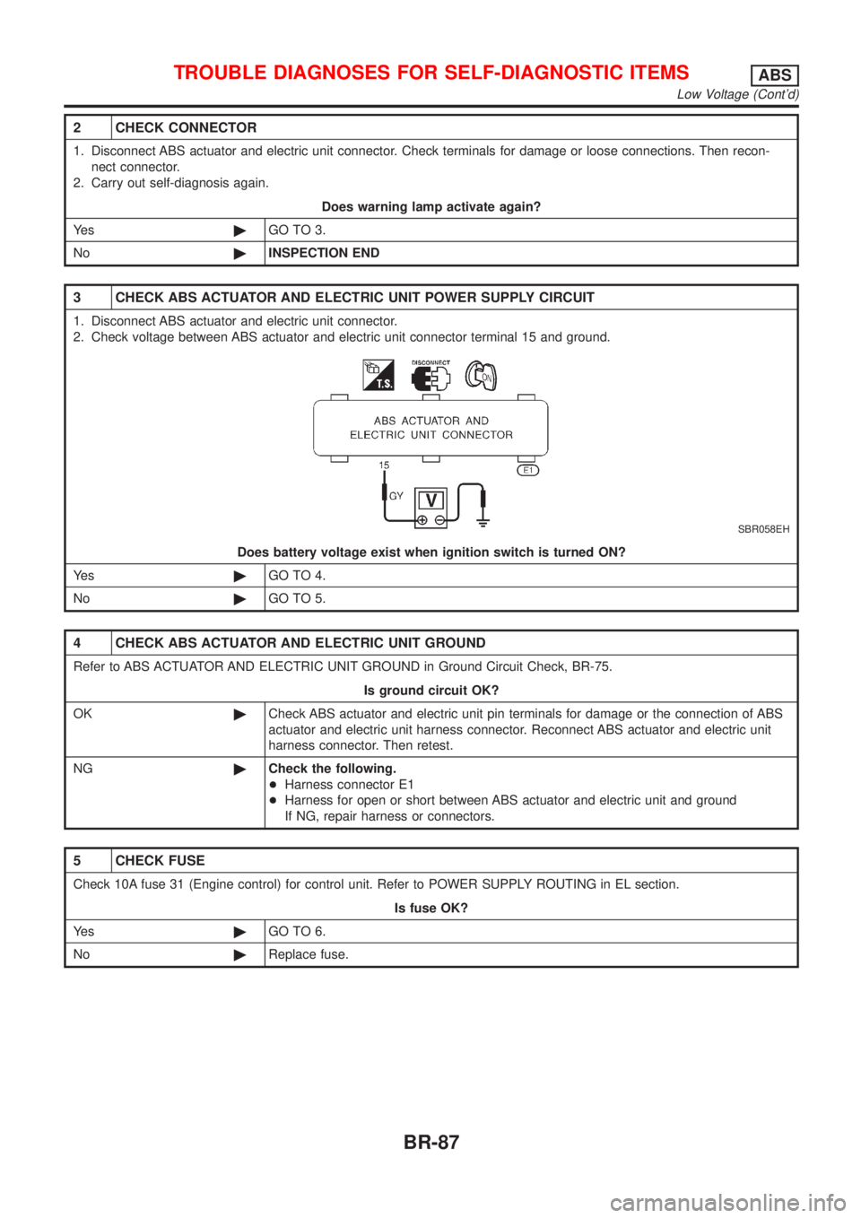
2 CHECK CONNECTOR
1. Disconnect ABS actuator and electric unit connector. Check terminals for damage or loose connections. Then recon-
nect connector.
2. Carry out self-diagnosis again.
Does warning lamp activate again?
Ye s©GO TO 3.
No©INSPECTION END
3 CHECK ABS ACTUATOR AND ELECTRIC UNIT POWER SUPPLY CIRCUIT
1. Disconnect ABS actuator and electric unit connector.
2. Check voltage between ABS actuator and electric unit connector terminal 15 and ground.
SBR058EH
Does battery voltage exist when ignition switch is turned ON?
Ye s©GO TO 4.
No©GO TO 5.
4 CHECK ABS ACTUATOR AND ELECTRIC UNIT GROUND
Refer to ABS ACTUATOR AND ELECTRIC UNIT GROUND in Ground Circuit Check, BR-75.
Is ground circuit OK?
OK©Check ABS actuator and electric unit pin terminals for damage or the connection of ABS
actuator and electric unit harness connector. Reconnect ABS actuator and electric unit
harness connector. Then retest.
NG©Check the following.
+Harness connector E1
+Harness for open or short between ABS actuator and electric unit and ground
If NG, repair harness or connectors.
5 CHECK FUSE
Check 10A fuse 31 (Engine control) for control unit. Refer to POWER SUPPLY ROUTING in EL section.
Is fuse OK?
Ye s©GO TO 6.
No©Replace fuse.
TROUBLE DIAGNOSES FOR SELF-DIAGNOSTIC ITEMSABS
Low Voltage (Cont'd)
BR-87
Page 608 of 2898

5. Pedal Vibration and Noise=NJBR0108
1 INSPECTION START
Pedal vibration and noise inspection
SAT797A
©GO TO 2.
2 CHECK SYMPTOM
1. Apply brake.
2. Start engine.
Does the symptom appear only when engine is started?
Ye s©Carry out self-diagnosis. Refer to BR-63, BR-65.
No©GO TO 3.
3 RECHECK SYMPTOM
Does the symptom appear when electrical equipment switches (such as headlamp) are operated?
Ye s©GO TO 4.
No©Go to ª3. CHECK WARNING LAMP INDICATIONº in ª2. Unexpected Pedal Actionº,
BR-89.
4 CHECK WHEEL SENSOR
Check wheel sensor shield ground. For location of shield ground, refer to wiring diagram and ªHARNESS LAYOUTº in EL
section.
Is wheel sensor shield grounded properly?
Ye s©Check ABS actuator and electric unit pin terminals for damage or the connection of ABS
actuator and electric unit harness connector. Reconnect ABS actuator and electric unit
harness connector. Then retest.
No©Repair.
NOTE:
ABS may operate and cause vibration under any of the following
conditions.
+Applying brake gradually when shifting or operating clutch.
+Low friction (slippery) road.
+High speed cornering.
+Driving over bumps and pot holes.
+Engine speed is over 5,000 rpm with vehicle stopped.
TROUBLE DIAGNOSES FOR SYMPTOMSABS
5. Pedal Vibration and Noise
BR-92
Page 616 of 2898

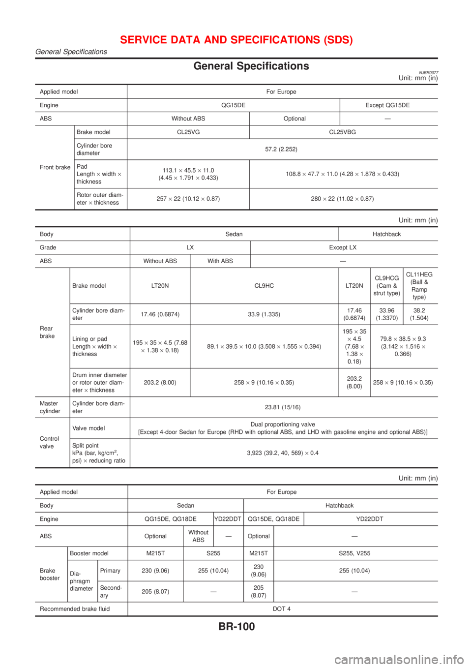
General SpecificationsNJBR0077Unit: mm (in)
Applied model For Europe
Engine QG15DE Except QG15DE
ABS Without ABS Optional Ð
Front brakeBrake model CL25VG CL25VBG
Cylinder bore
diameter57.2 (2.252)
Pad
Length´width´
thickness113.1´45.5´11.0
(4.45´1.791´0.433)108.8´47.7´11.0 (4.28´1.878´0.433)
Rotor outer diam-
eter´thickness257´22 (10.12´0.87) 280´22 (11.02´0.87)
Unit: mm (in)
Body Sedan Hatchback
Grade LX Except LX
ABS Without ABS With ABS Ð
Rear
brakeBrake model LT20N CL9HC LT20NCL9HCG
(Cam &
strut type)CL11HEG
(Ball &
Ramp
type)
Cylinder bore diam-
eter17.46 (0.6874) 33.9 (1.335)17.46
(0.6874)33.96
(1.3370)38.2
(1.504)
Lining or pad
Length´width´
thickness195´35´4.5 (7.68
´1.38´0.18)89.1´39.5´10.0 (3.508´1.555´0.394)195´35
´4.5
(7.68´
1.38´
0.18)79.8´38.5´9.3
(3.142´1.516´
0.366)
Drum inner diameter
or rotor outer diam-
eter´thickness203.2 (8.00) 258´9 (10.16´0.35)203.2
(8.00)258´9 (10.16´0.35)
Master
cylinderCylinder bore diam-
eter23.81 (15/16)
Control
valveValve modelDual proportioning valve
[Except 4-door Sedan for Europe (RHD with optional ABS, and LHD with gasoline engine and optional ABS)]
Split point
kPa (bar, kg/cm
2,
psi)´reducing ratio3,923 (39.2, 40, 569)´0.4
Unit: mm (in)
Applied model For Europe
Body Sedan Hatchback
Engine QG15DE, QG18DE YD22DDT QG15DE, QG18DE YD22DDT
ABS OptionalWithout
ABSÐ Optional Ð
Brake
boosterBooster model M215T S255 M215T S255, V255
Dia-
phragm
diameterPrimary 230 (9.06) 255 (10.04)230
(9.06)255 (10.04)
Second-
ary205 (8.07) Ð205
(8.07)Ð
Recommended brake fluid DOT 4
SERVICE DATA AND SPECIFICATIONS (SDS)
General Specifications
BR-100
Page 620 of 2898
Removal and Installation ...........................................75
REAR VIEW MIRROR...................................................76
Removal and Installation ...........................................76
REMOVAL...............................................................76
INSTALLATION........................................................76BODY (ALIGNMENT)....................................................77
Alignment ...................................................................77
ENGINE COMPARTMENT........................................78
UNDERBODY..........................................................80
CONTENTS(Cont'd)
BT-2